2005 NISSAN NAVARA towing
[x] Cancel search: towingPage 1623 of 3171
GI-1
GENERAL INFORMATION
A GENERAL INFORMATION
CONTENTS
C
D
E
F
G
H
I
J
K
L
MB
GI
SECTIONGI
GENERAL INFORMATION
PRECAUTIONS .......................................................... 3
Description ............................................................... 3
Precautions for Supplemental Restraint System
(SRS)“AIRBAG”and“SEATBELTPRE-TEN-
SIONER” .................................................................. 3
Precautions for NATS (NISSAN ANTI-THEFT SYS-
TEM) ........................................................................ 3
Precautions Necessary for Steering Wheel Rotation
After Battery Disconnect .......................................... 3
OPERATION PROCEDURE ................................. 4
General Precautions ................................................ 4
Precautions for Three Way Catalyst ......................... 5
Precautions for Fuel ................................................. 5
GASOLINE ENGINE ............................................. 5
DIESEL ENGINE ................................................... 6
Precautions for Multiport Fuel Injection System or
Engine Control System ............................................ 6
Precautions for Turbocharger (If Equipped) ............. 6
Precautions for Hoses .............................................. 6
HOSE REMOVAL AND INSTALLATION ............... 6
HOSE CLAMPING ................................................ 7
Precautions for Engine Oils ...................................... 7
HEALTH PROTECTION PRECAUTIONS ............. 7
ENVIRONMENTAL PROTECTION PRECAU-
TIONS ................................................................... 8
Precautions for Air Conditioning ............................... 8
HOW TO USE THIS MANUAL ................................... 9
Description ............................................................... 9
Terms ....................................................................... 9
Units ......................................................................... 9
Contents ................................................................... 9
Components ........................................................... 10
SYMBOLS ........................................................... 10
How to Follow Trouble Diagnoses ........................... 11
DESCRIPTION ..................................................... 11
HOW TO FOLLOW TEST GROUPS IN TROU-
BLE DIAGNOSES ................................................ 11
HARNESS WIRE COLOR AND CONNECTOR
NUMBER INDICATION ....................................... 12
KEY TO SYMBOLS SIGNIFYING MEASURE-MENTS OR PROCEDURES ............................... 13
How to Read Wiring Diagrams ............................... 15
CONNECTOR SYMBOLS ................................... 15
SAMPLE/WIRING DIAGRAM - EXAMPL - .......... 16
DESCRIPTION .................................................... 17
Abbreviations .......................................................... 23
SERVICE INFORMATION FOR ELECTRICAL INCI-
DENT ......................................................................... 24
How to Perform Efficient Diagnosis for an Electrical
Incident ................................................................... 24
WORK FLOW ...................................................... 24
INCIDENT SIMULATION TESTS ........................ 24
CIRCUIT INSPECTION ....................................... 27
Control Units and Electrical Parts ........................... 32
PRECAUTIONS .................................................. 32
CONTROL UNIT CONFIGURATION PROCEDURE... 34
Description .............................................................. 34
Part Replacement procedure Reference Table ...... 34
Work Procedure ...................................................... 36
Configuration (BCM) ............................................... 37
DESCRIPTION .................................................... 37
READ CONFIGURATION PROCEDURE ............ 37
WRITE CONFIGURATION PROCEDURE .......... 41
CONSULT-II CHECKING SYSTEM .......................... 47
Description .............................................................. 47
Function and System Application ........................... 47
Nickel Metal Hydride Battery Replacement ............ 48
Checking Equipment .............................................. 49
CONSULT-II Start Procedure .................................. 49
CONSULT-II Data Link Connector (DLC) Circuit .... 50
INSPECTION PROCEDURE .............................. 51
LIFTING POINT ......................................................... 52
Pantograph Jack, Garage Jack and Safety Stand... 52
2-Pole Lift ............................................................... 52
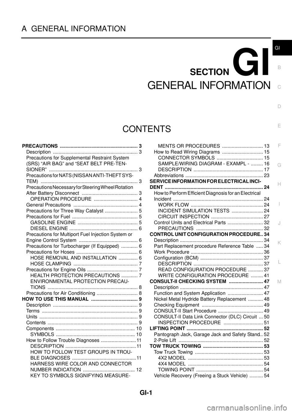
TOW TRUCK TOWING ............................................. 53
Tow Truck Towing ................................................... 53
4X2 MODEL ........................................................ 53
4X4 MODEL ........................................................ 54
TOWING POINT .................................................. 54
Vehicle Recovery (Freeing a Stuck Vehicle) ........... 54
Page 1675 of 3171
TOW TRUCK TOWING
GI-53
C
D
E
F
G
H
I
J
K
L
MB
GI
TOW TRUCK TOWINGPFP:00000
To w Tr u c k To w i n gEAS001DI
WARNING:
lNever get under the vehicle while it is supported only by the jack. Always use safety stands to
support the frame when you have to get under the vehicle.
lPlace wheel chocks at both front and back of the wheels on the ground.
CAUTION:
lAll applicable local laws regarding the towing operation must be obeyed.
lIt is necessary to use proper towing equipment to avoid possible damage during towing opera-
tion. Towing is in accordance with Towing Procedure Manual at dealer.
lAlways attach safety chains before towing.
lWhen towing, make sure that the transmission, steering system and powertrain are in good order.
If any unit is damaged, dollies must be used.
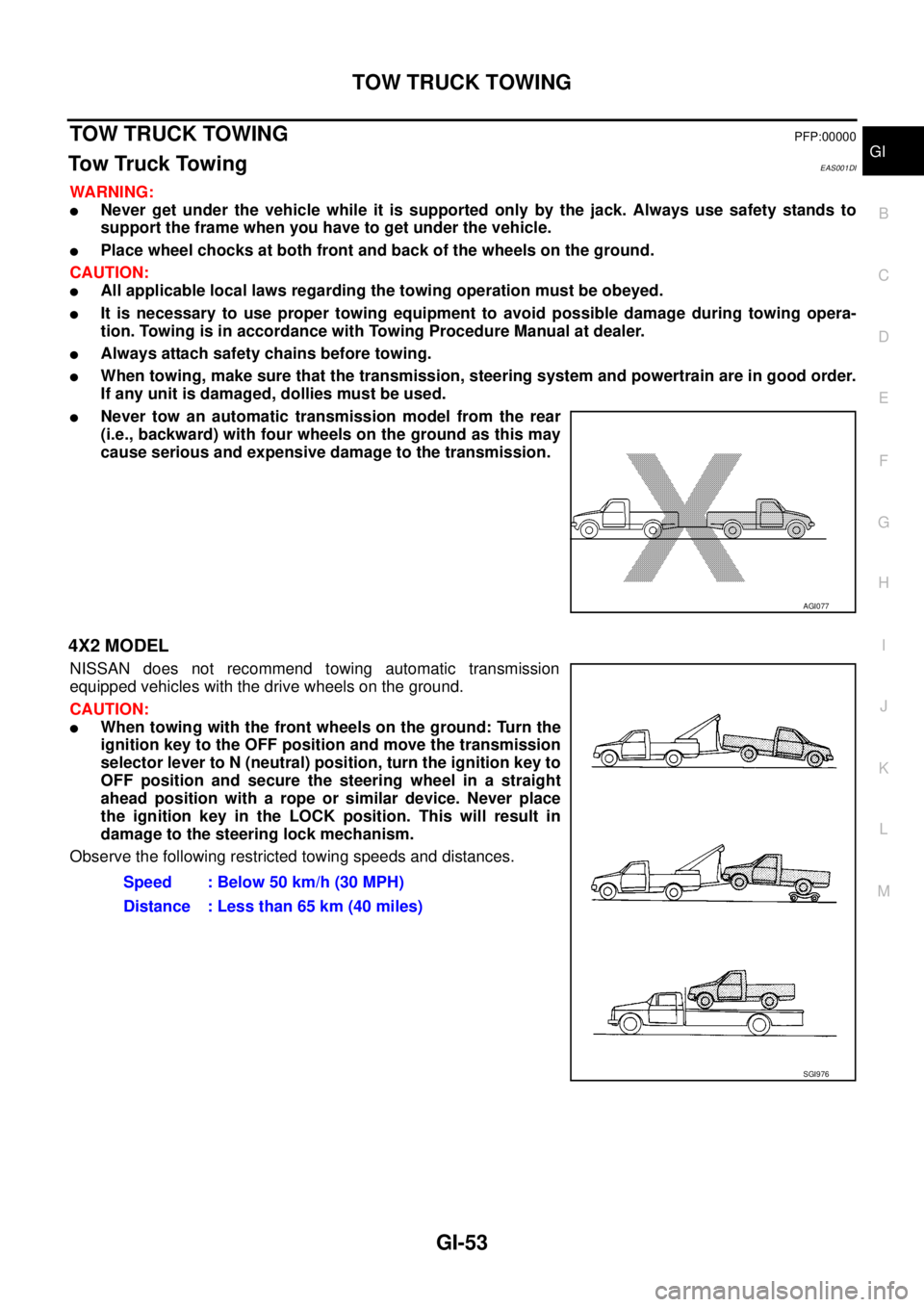
lNever tow an automatic transmission model from the rear
(i.e., backward) with four wheels on the ground as this may
cause serious and expensive damage to the transmission.
4X2 MODEL
NISSAN does not recommend towing automatic transmission
equipped vehicles with the drive wheels on the ground.
CAUTION:
lWhen towing with the front wheels on the ground: Turn the
ignition key to the OFF position and move the transmission
selector lever to N (neutral) position, turn the ignition key to
OFF position and secure the steering wheel in a straight
ahead position with a rope or similar device. Never place
the ignition key in the LOCK position. This will result in
damage to the steering lock mechanism.
Observe the following restricted towing speeds and distances.
AGI077
Speed : Below 50 km/h (30 MPH)
Distance : Less than 65 km (40 miles)
SGI976
Page 1676 of 3171
GI-54
TOW TRUCK TOWING
4X4 MODEL
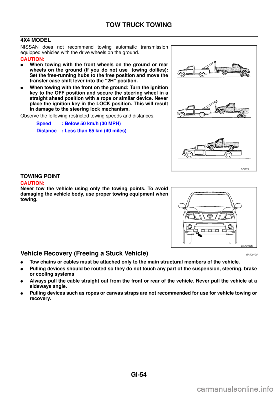
NISSAN does not recommend towing automatic transmission
equipped vehicles with the drive wheels on the ground.
CAUTION:
lWhen towing with the front wheels on the ground or rear
wheels on the ground (If you do not use towing dollies):
Set the free-running hubs to the free position and move the
transfer case shift lever into the “2H” position.
lWhen towing with the front on the ground: Turn the ignition
key to the OFF position and secure the steering wheel in a
straight ahead position with a rope or similar device. Never
place the ignition key in the LOCK position. This will result
in damage to the steering lock mechanism.
Observe the following restricted towing speeds and distances.
TOWING POINT
CAUTION:
Never tow the vehicle using only the towing points. To avoid
damaging the vehicle body, use proper towing equipment when
towing.
Vehicle Recovery (Freeing a Stuck Vehicle)EAS001DJ
lTow chains or cables must be attached only to the main structural members of the vehicle.
lPulling devices should be routed so they do not touch any part of the suspension, steering, brake
or cooling systems
lAlways pull the cable straight out from the front or rear of the vehicle. Never pull the vehicle at a
sideways angle.
lPulling devices such as ropes or canvas straps are not recommended for use for vehicle towing or
recovery.Speed : Below 50 km/h (30 MPH)
Distance : Less than 65 km (40 miles)
SGI973
LAIA0053E
Page 1759 of 3171
IDX-7
A
C
D
E
F
G
H
I
J
K
L B
IDX
ALPHABETICAL INDEX
Starter ................................................................SC-27
Starting system ..................................................SC-27
Steering gear, linkage and transfer gear inspection .....
MA-36
,MA-37
Steering linkage .................................................PS-14
Steering wheel and column .................................PS-8
Step lamp .........................................................LT-145
Stop lamp .........................................................LT-121
Stop lamp switch .............................................EC-330
STOP/L - Wiring diagram .................................LT-121
Striking rod (M/T) ...............................................MT-23
Strut (front) ......................................................FSU-10
Sun roof, electric ................................................RF-10
Sunload sensor ..............................................ATC-112
Sunroof ..................................................RF-10,RF-21
Super lock ...........................................................BL-55
Supplemental Restraint System ........................SRS-6
Symbols and abbreviations .....................GI-10,GI-23
Symptom matrix chart ........................................EC-42
Synchronizer (M/T) ............................................MT-21
T
Tachometer ..........................................................DI-4
Tail lamp ...........................................................LT-125
TAIL/L - Wiring diagram ....................................LT-127
TC boost control solnoid valve ........................EC-309
TC boost sensor ..............................................EC-153
TCC/V - Wiring diagram ..................................EC-311
TCM circuit diagram ..........................................AT-42
TCM inspection table .........................................AT-76
Thermostat ........................................................CO-24
Three way catalyst precautions ............................GI-5
Throttle body ......................................................EM-20
Tie-rod ...............................................................PS-14
Timing chain .........................................EM-73,EM-79
Timing gear ........................................................EM-79
Tire rotation .......................................................MA-34
Tire size ..............................................................GI-60
Torque converter installation ...........................AT-250
Torque convertor clutch solenoid valveAT-110,AT-112
Tow truck towing .................................................GI-53
Towing point .......................................................GI-54
Transfer control device .............TF-74,TF-78,TF-105
Transfer control unit inspection table ..................TF-38
Transfer oil replacement ....................................MA-32
Transfer serial number .......................................GI-58
Transmission case (M/T) ...................................MT-19
Transmission serial number ....................GI-58,GI-59
Tread-FR&RR (Dimensions) ..............................GI-60
Trim .....................................................................EI-33
Trouble diagnoses ..............................................GI-11
Turbine revolution sensor ................................AT-123
Turbocharger .....................................................EM-28
Turbocharger charge air cooler .........................EM-18
Turbocharger precautions ....................................GI-6
TURN - Wiring diagram ....................................LT-100
Turn signal lamp .................................................LT-97
Two-pole lift ........................................................GI-52
V
Vacuum hose drawing (Engine control) .............EC-16
Vacuum pump ...................................................EM-42
Valve clearance ................................................EM-66
Valve guide .....................................................EM-101
Valve lifter .........................................................EM-62
Valve seat .......................................................EM-103
Valve spring ....................................................EM-104
Vanity mirror lamp .............................................LT-145
Vehicle identification number ..............................GI-57
Vehicle recovery (freeing a stuck vehicle) ..........GI-54
VEHSEC - Wiring diagram ...............................BL-143
Viscosity number (SAE) ....................................MA-15
W
Wait detection switch ..............................TF-63
,TF-66
WARN - Wiring diagram .....................................DI-30
Warning chime ....................................................DI-51
Warning lamps ....................................................DI-28
Washer, front .....................................................WW-4
Water pump ......................................................CO-21
Water temperature gauge .....................................DI-4
Wheel alignment (front) .....................................FSU-7
Wheel balance ..................................................MA-34
Wheel bearing (front) .........................................FAX-5
Wheel bearing (rear) .........................................RAX-6
Wheel sensors (ABS) .....................................BRC-37
Wheel size ..........................................................GI-60
Wheelbase (Dimensions) ....................................GI-60
Width (Dimensions) ............................................GI-60
WINDOW - Wiring diagram ...............................GW-20
Window, door ......................................GW-35,GW-38
Window, rear .....................................................GW-43
Windshield ........................................................GW-11
WIPER - Wiring diagram ..................................WW-12
Wiper, front ........................................................WW-4
Wiring Diagram (Cell code) list ..........................PG-68
Wiring diagrams ..................................................GI-15
Page 2285 of 3171
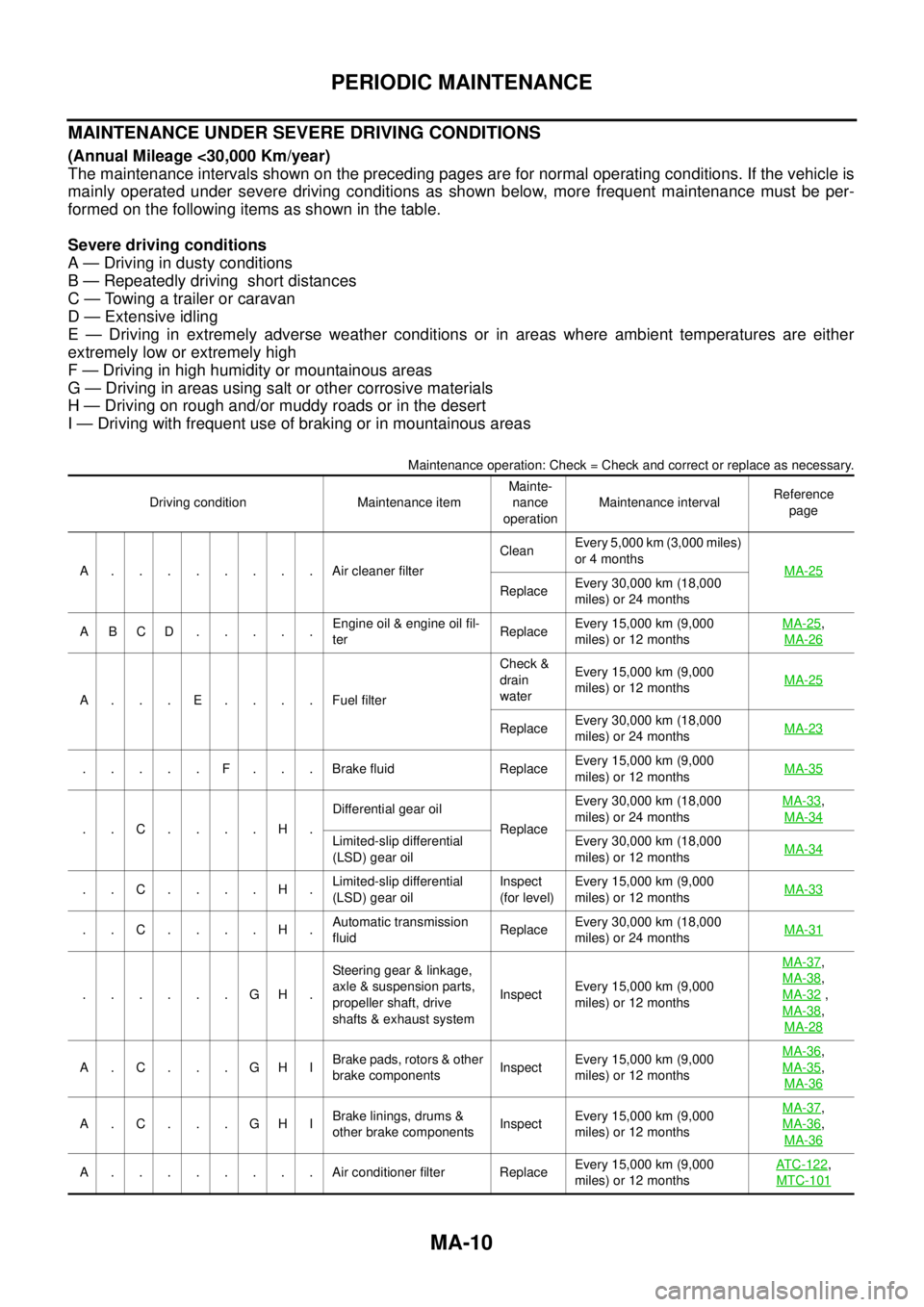
MA-10
PERIODIC MAINTENANCE
MAINTENANCE UNDER SEVERE DRIVING CONDITIONS
(Annual Mileage <30,000 Km/year)
The maintenance intervals shown on the preceding pages are for normal operating conditions. If the vehicle is
mainly operated under severe driving conditions as shown below, more frequent maintenance must be per-
formed on the following items as shown in the table.
Severe driving conditions
A — Driving in dusty conditions
B — Repeatedly driving short distances
C — Towing a trailer or caravan
D — Extensive idling
E — Driving in extremely adverse weather conditions or in areas where ambient temperatures are either
extremely low or extremely high
F — Driving in high humidity or mountainous areas
G — Driving in areas using salt or other corrosive materials
H — Driving on rough and/or muddy roads or in the desert
I — Driving with frequent use of braking or in mountainous areas
Maintenance operation: Check = Check and correct or replace as necessary.
Driving condition Maintenance itemMainte-
nance
operationMaintenance intervalReference
page
A........AircleanerfilterCleanEvery 5,000 km (3,000 miles)
or 4 months
MA-25
ReplaceEvery 30,000 km (18,000
miles) or 24 months
ABCD.....Engine oil & engine oil fil-
terReplaceEvery 15,000 km (9,000
miles) or 12 monthsMA-25
,
MA-26
A . . . E . . . . Fuel filterCheck &
drain
waterEvery 15,000 km (9,000
miles) or 12 monthsMA-25
ReplaceEvery 30,000 km (18,000
miles) or 24 monthsMA-23
. . . . . F . . . Brake fluid ReplaceEvery 15,000 km (9,000
miles) or 12 monthsMA-35
..C....H.Differential gear oil
ReplaceEvery 30,000 km (18,000
miles) or 24 monthsMA-33
,
MA-34
Limited-slip differential
(LSD) gear oilEvery 30,000 km (18,000
miles) or 12 monthsMA-34
..C....H.Limited-slip differential
(LSD) gear oilInspect
(for level)Every 15,000 km (9,000
miles) or 12 monthsMA-33
..C....H.Automatic transmission
fluidReplaceEvery 30,000 km (18,000
miles) or 24 monthsMA-31
......GH.Steering gear & linkage,
axle & suspension parts,
propeller shaft, drive
shafts & exhaust systemInspectEvery 15,000 km (9,000
miles) or 12 monthsMA-37
,
MA-38
,
MA-32
,
MA-38
,
MA-28
A.C. . .GHIBrake pads, rotors & other
brake componentsInspectEvery 15,000 km (9,000
miles) or 12 monthsMA-36
,
MA-35
,
MA-36
A.C. . .GHIBrake linings, drums &
other brake componentsInspectEvery 15,000 km (9,000
miles) or 12 monthsMA-37
,
MA-36
,
MA-36
A . . . . . . . . Air conditioner filter ReplaceEvery 15,000 km (9,000
miles) or 12 monthsAT C - 1 2 2,
MTC-101
Page 2288 of 3171
PERIODIC MAINTENANCE
MA-13
C
D
E
F
G
H
I
J
K
MA
B
MA
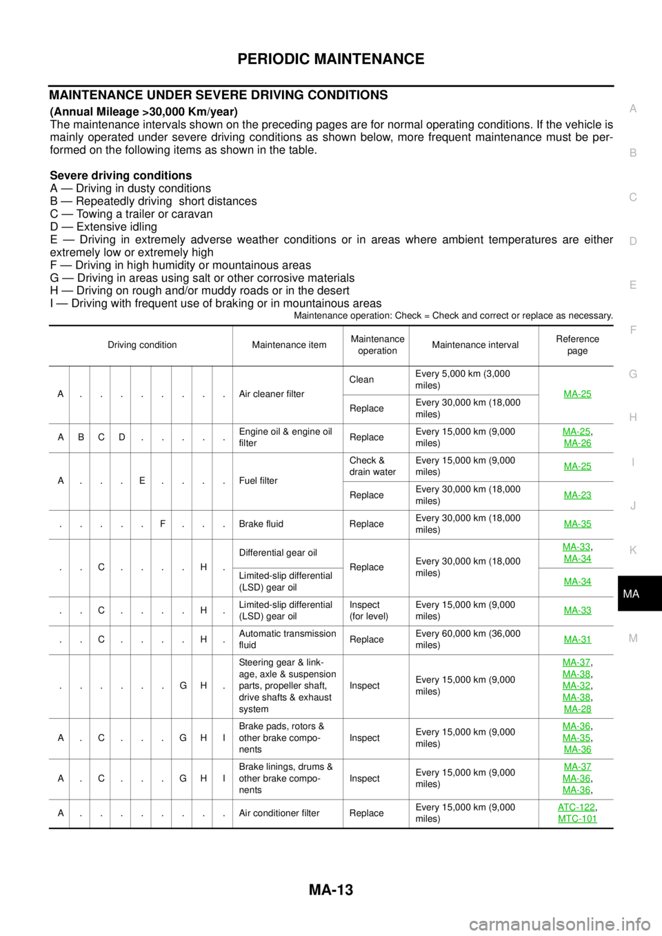
MAINTENANCE UNDER SEVERE DRIVING CONDITIONS
(Annual Mileage >30,000 Km/year)
The maintenance intervals shown on the preceding pages are for normal operating conditions. If the vehicle is
mainly operated under severe driving conditions as shown below, more frequent maintenance must be per-
formed on the following items as shown in the table.
Severe driving conditions
A — Driving in dusty conditions
B — Repeatedly driving short distances
C — Towing a trailer or caravan
D — Extensive idling
E — Driving in extremely adverse weather conditions or in areas where ambient temperatures are either
extremely low or extremely high
F — Driving in high humidity or mountainous areas
G — Driving in areas using salt or other corrosive materials
H — Driving on rough and/or muddy roads or in the desert
I — Driving with frequent use of braking or in mountainous areas
Maintenance operation: Check = Check and correct or replace as necessary.
Driving condition Maintenance itemMaintenance
operationMaintenance intervalReference
page
A........Aircleaner filterCleanEvery 5,000 km (3,000
miles)
MA-25
ReplaceEvery 30,000 km (18,000
miles)
ABCD.....Engine oil & engine oil
filterReplaceEvery 15,000 km (9,000
miles)MA-25
,
MA-26
A...E....FuelfilterCheck &
drain waterEvery 15,000 km (9,000
miles)MA-25
ReplaceEvery 30,000 km (18,000
miles)MA-23
.....F...Brakefluid ReplaceEvery 30,000 km (18,000
miles)MA-35
..C....H.Differential gear oil
ReplaceEvery 30,000 km (18,000
miles)MA-33
,
MA-34
Limited-slip differential
(LSD) gear oilMA-34
..C....H.Limited-slip differential
(LSD) gear oilInspect
(for level)Every 15,000 km (9,000
miles)MA-33
..C....H.Automatic transmission
fluidReplaceEvery 60,000 km (36,000
miles)MA-31
......GH.Steering gear & link-
age, axle & suspension
parts, propeller shaft,
drive shafts & exhaust
systemInspectEvery 15,000 km (9,000
miles)MA-37
,
MA-38
,
MA-32
,
MA-38
,
MA-28
A.C...GHIBrake pads, rotors &
other brake compo-
nentsInspectEvery 15,000 km (9,000
miles)MA-36
,
MA-35
,
MA-36
A.C...GHIBrake linings, drums &
other brake compo-
nentsInspectEvery 15,000 km (9,000
miles)MA-37MA-36,
MA-36
,
A........Airconditioner filter ReplaceEvery 15,000 km (9,000
miles)ATC-122
,
MTC-101
Page 2307 of 3171
MA-32
CHASSIS AND BODY MAINTENANCE
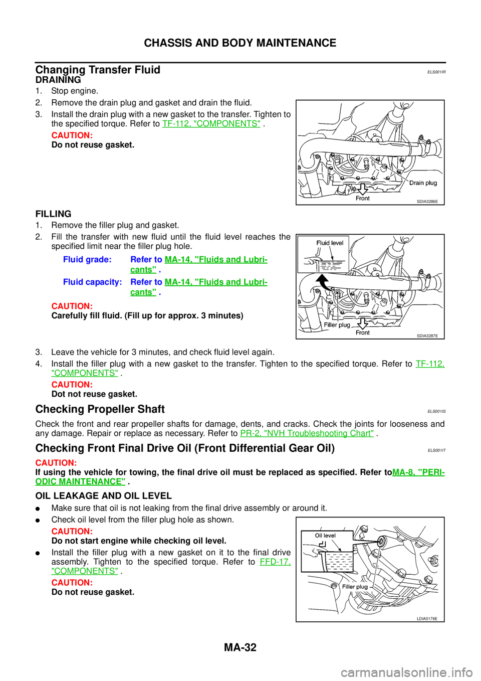
Changing Transfer Fluid
ELS001IR
DRAINING
1. Stop engine.
2. Remove the drain plug and gasket and drain the fluid.
3. Install the drain plug with a new gasket to the transfer. Tighten to
the specified torque. Refer toTF-112, "
COMPONENTS".
CAUTION:
Do not reuse gasket.
FILLING
1. Remove the filler plug and gasket.
2. Fill the transfer with new fluid until the fluid level reaches the
specified limit near the filler plug hole.
CAUTION:
Carefully fill fluid. (Fill up for approx. 3 minutes)
3. Leave the vehicle for 3 minutes, and check fluid level again.
4. Install the filler plug with a new gasket to the transfer. Tighten to the specified torque. Refer toTF-112,
"COMPONENTS".
CAUTION:
Dot not reuse gasket.
Checking Propeller ShaftELS001IS
Check the front and rear propeller shafts for damage, dents, and cracks. Check the joints for looseness and
any damage. Repair or replace as necessary. Refer toPR-2, "
NVH Troubleshooting Chart".
Checking Front Final Drive Oil (Front Differential Gear Oil)ELS001IT
CAUTION:
If using the vehicle for towing, the final drive oil must be replaced as specified. Refer toMA-8, "
PERI-
ODIC MAINTENANCE".
OIL LEAKAGE AND OIL LEVEL
lMake sure that oil is not leaking from the final drive assembly or around it.
lCheck oil level from the filler plug hole as shown.
CAUTION:
Do not start engine while checking oil level.
lInstall the filler plug with a new gasket on it to the final drive
assembly. Tighten to the specified torque. Refer toFFD-17,
"COMPONENTS".
CAUTION:
Do not reuse gasket.
SDIA3286E
Fluid grade: Refer toMA-14, "Fluids and Lubri-
cants".
Fluid capacity: Refer toMA-14, "
Fluids and Lubri-
cants".
SDIA3287E
LDIA0176E
Page 2308 of 3171
CHASSIS AND BODY MAINTENANCE
MA-33
C
D
E
F
G
H
I
J
K
MA
B
MA
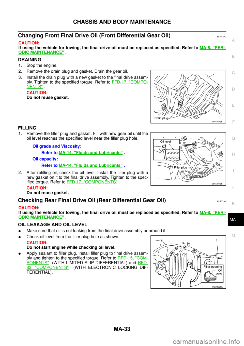
Changing Front Final Drive Oil (Front Differential Gear Oil)ELS001IU
CAUTION:
If using the vehicle for towing, the final drive oil must be replaced as specified. Refer toMA-8, "
PERI-
ODIC MAINTENANCE".
DRAINING
1. Stop the engine.
2. Remove the drain plug and gasket. Drain the gear oil.
3. Install the drain plug with a new gasket to the final drive assem-
bly. Tighten to the specified torque. Refer toFFD-17, "
COMPO-
NENTS".
CAUTION:
Do not reuse gasket.
FILLING
1. Remove the filler plug and gasket. Fill with new gear oil until the
oil level reaches the specified level near the filler plug hole.
2. After refilling oil, check the oil level. Install the filler plug with a
new gasket on it to the final drive assembly. Tighten to the spec-
ified torque. Refer toFFD-17, "
COMPONENTS".
CAUTION:
Do not reuse gasket.
Checking Rear Final Drive Oil (Rear Differential Gear Oil)ELS001IV
CAUTION:
If using the vehicle for towing, the final drive oil must be replaced as specified. Refer toMA-8, "
PERI-
ODIC MAINTENANCE".
OIL LEAKAGE AND OIL LEVEL
lMake sure that oil is not leaking from the final drive assembly or around it.
lCheck oil level from the filler plug hole as shown.
CAUTION:
Do not start engine while checking oil level.
lApply sealant to filler plug. Install filler plug to final drive assem-
bly and tighten to the specified torque. Refer toRFD-15, "
COM-
PONENTS"(WITH LIMITED SLIP DIFFERENTIAL) andRFD-
82, "COMPONENTS"(WITH ELECTRONIC LOCKING DIF-
FERENTIAL).
LDIA0175E
OilgradeandViscosity:
Refer toMA-14, "
Fluids and Lubricants".
Oil capacity:
Refer toMA-14, "
Fluids and Lubricants".
LDIA0176E
PDIA1039E