2005 NISSAN NAVARA wipers
[x] Cancel search: wipersPage 2280 of 3171

DESCRIPTION
MA-5
C
D
E
F
G
H
I
J
K
MA
B
MA
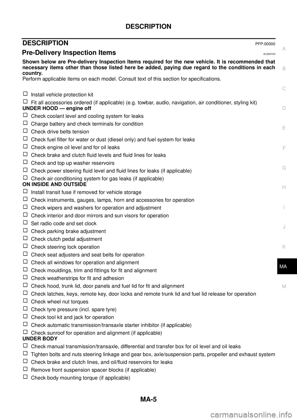
DESCRIPTIONPFP:00000
Pre-Delivery Inspection ItemsELS001K2
Shown below are Pre-delivery Inspection Items required for the new vehicle. It is recommended that
necessary items other than those listed here be added, paying due regard to the conditions in each
country.
Perform applicable items on each model. Consult text of this section for specifications.
Install vehicle protection kit
Fit all accessories ordered (if applicable) (e.g. towbar, audio, navigation, air conditioner, styling kit)
UNDER HOOD — engine off
Check coolant level and cooling system for leaks
Charge battery and check terminals for condition
Check drive belts tension
Check fuel filter for water or dust (diesel only) and fuel system for leaks
Check engine oil level and for oil leaks
Check brake and clutch fluid levels and fluid lines for leaks
Check and top up washer reservoirs
Check power steering fluid level and fluid lines for leaks (if applicable)
Check air conditioning system for gas leaks (if applicable)
ON INSIDE AND OUTSIDE
Install transit fuse if removed for vehicle storage
Check instruments, gauges, lamps, horn and accessories for operation
Check wipers and washers for operation and adjustment
Check interior and door mirrors and sun visors for operation
Set radio code and set clock
Check parking brake adjustment
Check clutch pedal adjustment
Check steering lock operation
Check seat adjusters and seat belts for operation
Check all windows for operation and alignment
Check mouldings, trim and fittings for fit and alignment
Check weatherstrips for fit and adhesion
Check hood, trunk lid, door panels and fuel lid for fit and alignment
Check latches, keys, remote key, door locks and remote trunk lid and fuel lid release for operation
Check wheel nut torques
Check tyre pressure (incl. spare tyre)
Check tool kit and jack for operation
Check automatic transmission/transaxle starter inhibitor (if applicable)
Check sunroof for operation and alignment (if applicable)
UNDER BODY
Check manual transmission/transaxle, differential and transfer box for oil level and oil leaks
Tighten bolts and nuts steering linkage and gear box, axle/suspension parts, propeller and exhaust system
Check brake and clutch lines, and oil/fluid reservoirs for leaks
Remove front suspension spacer blocks (if applicable)
Check body mounting torque (if applicable)
Page 2543 of 3171

PG-14
IPDM E/R (INTELLIGENT POWER DISTRIBUTION MODULE ENGINE ROOM)
IPDM E/R (INTELLIGENT POWER DISTRIBUTION MODULE ENGINE ROOM)
PFP:284B7
System DescriptionEKS00PA8
lIPDM E/R (Intelligent Power Distribution Module Engine Room) integrates the relay box and fuse block
which were originally placed in engine compartment. It controls integrated relays via IPDM E/R control cir-
cuits.
lIPDM E/R-integrated control circuits perform ON-OFF operation of relays, CAN communication control,
etc.
lIt controls operation of each electrical component via ECM, BCM and CAN communication lines.
CAUTION:
None of the IPDM E/R integrated relays can be removed.
SYSTEMS CONTROLLED BY IPDM E/R
IPDM E/R receives a request signal from each Control unit with CAN communication. It controls each system.
CAN COMMUNICATION LINE CONTROL
With CAN communication, by connecting each control unit using two communication lines (CAN L-line, CAN
H-line), it is possible to transmit a maximum amount of information with minimum wiring. Each control unit can
transmit and receive data, and reads necessary information only.
1. Fail-safe control
lWhen CAN communication with other control units is impossible, IPDM E/R performs fail-safe control.
After CAN communication returns to normal operation, it also returns to normal control.
lOperation of control parts by IPDM E/R during fail-safe mode is as follows:
Control system Transmit control unit Control part
Lamp control BCM
lHead lamps (HI, LO)
lTail lamps, parking and license plate lamps
lFront fog lamps
Wiper control BCM Front wipers
Rear window defogger control BCM Rear window defogger
A/C compressor control ECM A/C compressor
Starter control TCM Starter motor
Cooling fan control ECM Cooling fan
Controlled system Fail-safe mode
Headlamps
lWith the ignition switch ON, the headlamp low is ON.
lWith the ignition switch OFF, the headlamp low is OFF.
Tail, parking and license plate lamps
lWith the ignition switch ON, the tail lamp is ON.
lWith the ignition switch OFF, the tail lamp is OFF.
Cooling fan
lWith the ignition switch ON, the cooling fan HI operates.
lWith the ignition switch OFF, the cooling fan stops.
Front wipersUntil the ignition switch is turned off, the front wiper LO and HI remains in the same status it
was in just before fail-safe control was initiated.
Rear window defogger Rear window defogger OFF
A/C compressor A/C compressor OFF
Front fog lamps Front fog lamp OFF
Page 2550 of 3171

IPDM E/R (INTELLIGENT POWER DISTRIBUTION MODULE ENGINE ROOM)
PG-21
C
D
E
F
G
H
I
J
L
MA
B
PG
Diagnosis chart in auto active test mode
Symptom Inspection contents Possible cause
Any of front wipers, tail
and parking lamps, front
fog lamps, and
headlamps (HI, LO) do
not operate.Perform auto active
test. Does system in
question operate?YES
lBCM signal input system malfunction
NO
lLamp/wiper motor malfunction
lLamp/wiper motor ground circuit malfunction
lHarness/connector malfunction between IPDM E/R and system in
question
lIPDM E/R (integrated relay) malfunction
Rear window defogger
does not operate.Perform auto active
test. Does rear win-
dow defogger oper-
ate?YES
lBCM signal input circuit malfunction
NO
lRear window defogger relay malfunction
lOpen circuit of rear window defogger
lHarness or connector malfunction between IPDM E/R and rear window
defogger
lIPDM E/R (integrated relay) malfunction
A/C compressor does
not operate.Perform auto active
test. Does magnetic
clutch operate?YES
lBCM signal input circuit malfunction
lCAN communication signal malfunction between BCM and ECM
lCAN communication signal malfunction between ECM and IPDM E/R
NO
lMagnetic clutch malfunction
lHarness/connector malfunction between IPDM E/R and magnetic
clutch
lIPDM E/R (integrated relay) malfunction
Cooling fan does not
operate.Perform auto active
test. Does cooling fan
operate?YES
lECM signal input circuit malfunction
lCAN communication signal malfunction between ECM and IPDM E/R
NO
lCooling fan motor malfunction
lHarness/connector malfunction between IPDM E/R and cooling fan
motor
lIPDM E/R (integrated relay) malfunction
Oil pressure warning
lamp does not operate.Perform auto active
test. Does oil pres-
sure warning lamp
blink?YES
lHarness/connector malfunction between IPDM E/R and oil pressure
switch
lOil pressure switch malfunction
lIPDM E/R malfunction
NO
lCAN communication signal malfunction between IPDM E/R and combi-
nation meter
lCombination meter malfunction
Page 3112 of 3171

WW-1
WIPER, WASHER & HORN
K ELECTRICAL
CONTENTS
C
D
E
F
G
H
I
J
L
M
SECTIONWW
A
B
WW
WIPER, WASHER & HORN
PRECAUTION ............................................................ 3
Precautions for Supplemental Restraint System
(SRS)“AIRBAG”and“SEATBELTPRE-TEN-
SIONER” .................................................................. 3
Wiring Diagrams and Trouble Diagnosis .................. 3
FRONT WIPER AND WASHER SYSTEM .................. 4
Components Parts and Harness Connector Loca-
tion ........................................................................... 4
System Description .................................................. 4
LOW SPEED WIPER OPERATION ...................... 5
HI SPEED WIPER OPERATION ........................... 5
INTERMITTENT OPERATION .............................. 6
AUTO STOP OPERATION .................................... 6
FRONT WASHER OPERATION ........................... 6
MIST OPERATION ................................................ 7
FAIL-SAFE FUNCTION ......................................... 7
COMBINATION SWITCH READING FUNCTION..... 8
CAN Communication System Description .............. 10
Schematic ............................................................... 11
Wiring Diagram — WIPER — ................................ 12
Terminals and Reference Values for BCM ............. 15
Terminals and Reference Values for IPDM E/R ..... 16
How To Proceed With Trouble Diagnosis ............... 16
Preliminary Inspection ............................................ 16
INSPECTION FOR POWER SUPPLY AND
GROUND CIRCUIT ............................................. 16
CONSULT-II Function (BCM) ................................. 18
CONSULT-II OPERATION .................................. 18
WORK SUPPORT ............................................... 19
DATA MONITOR ................................................. 19
ACTIVE TEST ..................................................... 20
CONSULT-II Function (IPDM E/R) ......................... 21
CONSULT-II OPERATION .................................. 21
DATA MONITOR ................................................. 22
ACTIVE TEST ..................................................... 22
Front Wiper Does Not Operate in Rain (Front Wiper
Switch Turned to INT Position) ............................... 23
Front Wiper Does Not Operate .............................. 25
Front Wiper Does Not Return to Stop Position (After
Front Wiper for 10 Seconds, They Stop for 20 sec-onds, and After Repeating the Operations Five
Times, They Become Inoperative) .......................... 28
Only Front Wiper LO Does Not Operate ................. 29
Only Front Wiper HI Does Not Operate .................. 31
Only Front Wiper INT Does Not Operate ................ 32
Front Wiper Intermittent Operation Switch Position
Cannot Be Adjusted ................................................ 33
Front Wiper Interval Time Is Not Controlled by Vehi-
cle Speed ................................................................ 33
Wipers Do Not Wipe When Front Washer Operates... 33
Removal and Installation of Front Wiper Arms,
Adjustment of Wiper Arms Stop Location ............... 34
REMOVAL ........................................................... 34
INSTALLATION ................................................... 34
Removal and Installation of Wiper Motor and Link-
age .......................................................................... 35
REMOVAL ........................................................... 35
INSTALLATION ................................................... 35
Washer Nozzle Adjustment .................................... 36
Washer Tube Layout .............................................. 36
Removal and Installation of Wiper and Washer
Switch ..................................................................... 36
REMOVAL ........................................................... 36
INSTALLATION ................................................... 36
Removal and Installation of Front Washer Tank ..... 37
REMOVAL ........................................................... 37
INSTALLATION ................................................... 37
Removal and Installation of Front Washer Motor ... 38
REMOVAL ........................................................... 38
INSTALLATION ................................................... 38
Removal and Installation of Washer Fluid Level Sen-
sor ........................................................................... 38
REMOVAL ........................................................... 38
INSTALLATION ................................................... 38
HEADLAMP WASHER ............................................. 39
Components Parts and Harness Connector Loca-
tion .......................................................................... 39
System Description ................................................. 39
OUTLINE ............................................................. 40
HEADLAMP WASHER OPERATION .................. 40
Page 3117 of 3171

WW-6
FRONT WIPER AND WASHER SYSTEM
INTERMITTENT OPERATION
When front wiper switch is turned to INT position, wiper performs intermittent operation, low-speed operation,
and high-speed operation according to water drop increase rate on windshield detected by light and rain sen-
sor. If light and rain sensor malfunctions, it operates as vehicle speed sensing wiper during driving and oper-
ates intermittent operation according to INT-volume switch with vehicle stopped. During this time, BCM
controls each operation.
The BCM then sends a front wiper (HI or LOW) request signal with CAN communication.
lfrom BCM terminals 21 and 22
lto IPDM E/R terminals 39 and 40.
When the BCM determines that combination switch status is front wiper intermittent ON, it performs the follow-
ing operations.
lBCM detects intermittent wiper dial position.
lBCM sends front wiper request signal (HI or LOW) to IPDM E/R at calculated operation interval.
When IPDM E/R receives front wiper request signal (HI or LOW), it supplies ground to energize the front wiper
main relay and front wiper LOW/HIGH relay. It then sends an auto-stop signal to the BCM, and conducts inter-
mittent front wiper motor operation.
AUTO STOP OPERATION
When the wiper arms are not located at the base of the windshield, and the wiper switch is turned OFF, the
wiper motor will continue to operate until the wiper arms reach the windshield base. When the wiper arms
reach the base of windshield, front wiper motor terminals 2 and 5 are connected.
Ground is supplied
lto IPDM E/R terminal 43
lthrough front wiper motor terminal 5
lthrough front wiper motor terminal 2
lthrough grounds E21, E41 and E61.
The IPDM E/R sends an auto stop operation signal to the BCM with CAN communication.
When the BCM receives an auto stop operation signal, the BCM sends wiper stop signal to the IPDM E/R over
CAN communication lines. The IPDM E/R then de-energizes the front wiper main relay.
The wiper motor will then stop the wiper arms at the STOP position.
FRONT WASHER OPERATION
When the ignition switch is in the ON or START position, and the front washer switches are OFF, the front
washer motor is supplied power
lthrough 10A fuse [No. 15, located in fuse block (J/B)]
lthrough combination switch (wiper switch) terminal 2
lthrough combination switch (wiper switch) terminal 4
lto front washer motor terminal 1.
When the front wiper switch is in the front washer position, the BCM detects a front washer signal request
through the combination switch (wiper switch) reading function.
Combination switch ground is supplied
lto front washer motor terminal 2
lthrough combination switch (wiper switch) terminal 3
lthrough combination switch (wiper switch) terminal 9
lthrough grounds M21, M80 and M83.
With ground supplied, the front washer motor is operated in the front direction.
When the BCM detects that front washer motor has operated for 0.4 seconds or longer, the BCM uses CAN
communication and sends a wiper request signal to the IPDM E/R for low speed operation of wipers.
When the BCM detects that the washer switch is OFF, low speed operation cycles approximately 3 times and
then stops.
Page 3119 of 3171

WW-8
FRONT WIPER AND WASHER SYSTEM
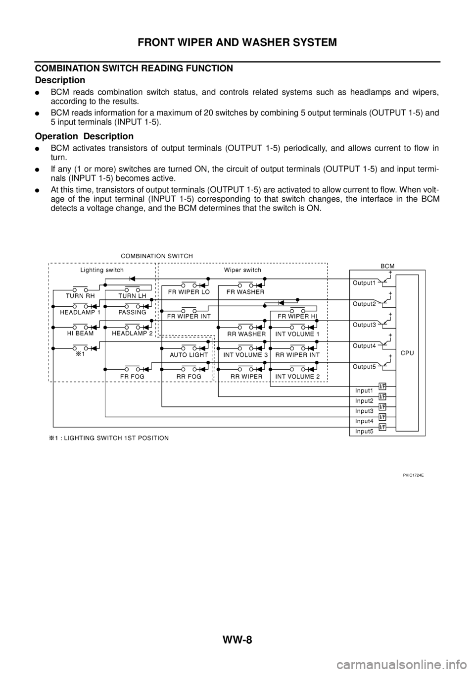
COMBINATION SWITCH READING FUNCTION
Description
lBCM reads combination switch status, and controls related systems such as headlamps and wipers,
according to the results.
lBCM reads information for a maximum of 20 switches by combining 5 output terminals (OUTPUT 1-5) and
5 input terminals (INPUT 1-5).
Operation Description
lBCM activates transistors of output terminals (OUTPUT 1-5) periodically, and allows current to flow in
turn.
lIf any (1 or more) switches are turned ON, the circuit of output terminals (OUTPUT 1-5) and input termi-
nals (INPUT 1-5) becomes active.
lAt this time, transistors of output terminals (OUTPUT 1-5) are activated to allow current to flow. When volt-
age of the input terminal (INPUT 1-5) corresponding to that switch changes, the interface in the BCM
detects a voltage change, and the BCM determines that the switch is ON.
PKIC1724E
Page 3136 of 3171

FRONT WIPER AND WASHER SYSTEM
WW-25
C
D
E
F
G
H
I
J
L
MA
B
WW
Front Wiper Does Not OperateEKS00P56
CAUTION:
During IPDM E/R fail-safe control, front wipers may not operate. Refer toPG-14, "
CAN COMMUNICA-
TION LINE CONTROL"to make sure that it is not in fail-safe status.
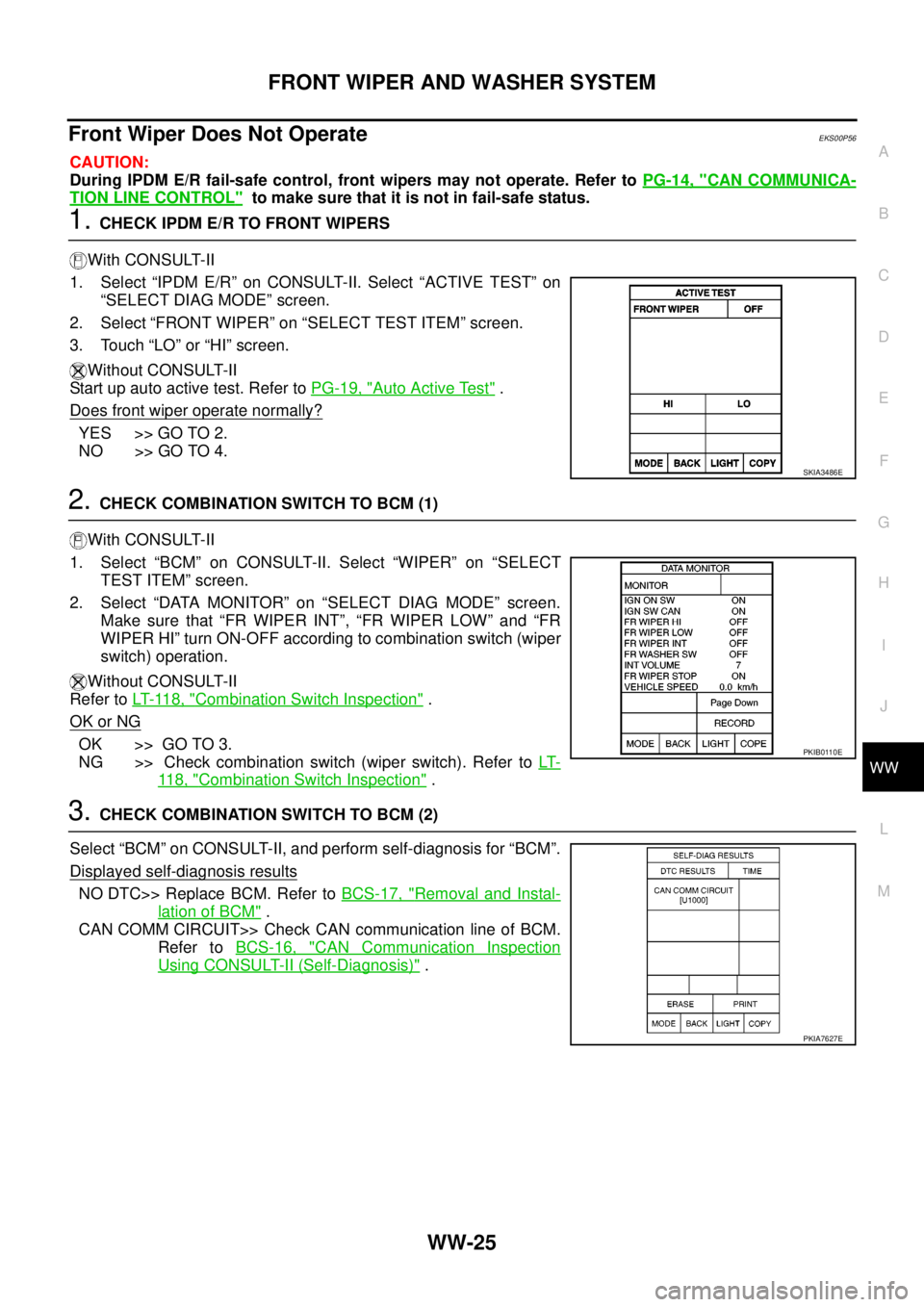
1.CHECK IPDM E/R TO FRONT WIPERS
With CONSULT-II
1. Select “IPDM E/R” on CONSULT-II. Select “ACTIVE TEST” on
“SELECT DIAG MODE” screen.
2. Select “FRONT WIPER” on “SELECT TEST ITEM” screen.
3. Touch “LO” or “HI” screen.
Without CONSULT-II
Start up auto active test. Refer toPG-19, "
Auto Active Test".
Does front wiper operate normally?
YES >> GO TO 2.
NO >> GO TO 4.
2.CHECK COMBINATION SWITCH TO BCM (1)
With CONSULT-II
1. Select “BCM” on CONSULT-II. Select “WIPER” on “SELECT
TEST ITEM” screen.
2. Select “DATA MONITOR” on “SELECT DIAG MODE” screen.
Make sure that “FR WIPER INT”, “FR WIPER LOW” and “FR
WIPER HI” turn ON-OFF according to combination switch (wiper
switch) operation.
Without CONSULT-II
Refer toLT- 11 8 , "
Combination Switch Inspection".
OK or NG
OK >> GO TO 3.
NG >> Check combination switch (wiper switch). Refer toLT-
11 8 , "Combination Switch Inspection".
3.CHECK COMBINATION SWITCH TO BCM (2)
Select “BCM” on CONSULT-II, and perform self-diagnosis for “BCM”.
Displayed self-diagnosis results
NO DTC>> Replace BCM. Refer toBCS-17, "Removal and Instal-
lation of BCM".
CAN COMM CIRCUIT>> Check CAN communication line of BCM.
Refer toBCS-16, "
CAN Communication Inspection
Using CONSULT-II (Self-Diagnosis)".
SKIA3486E
PKIB0110E
PKIA7627E
Page 3139 of 3171

WW-28
FRONT WIPER AND WASHER SYSTEM
Front Wiper Does Not Return to Stop Position (After Front Wiper for 10 Sec-
onds, They Stop for 20 seconds, and After Repeating the Operations Five
Times, They Become Inoperative)
EKS00P57
CAUTION:
lWhen auto stop signal has not varied for 10 seconds or longer while IPDM E/R is operating front
wipers, IPDM E/R considers front wipers are locked, and stops wiper output. That causes this
symptom.
lThis status can be checked by “DATA MONITOR” of “IPDM E/R” on which “WIPER PROTECTION”
ITEMS SHOWS “BLOCK”.
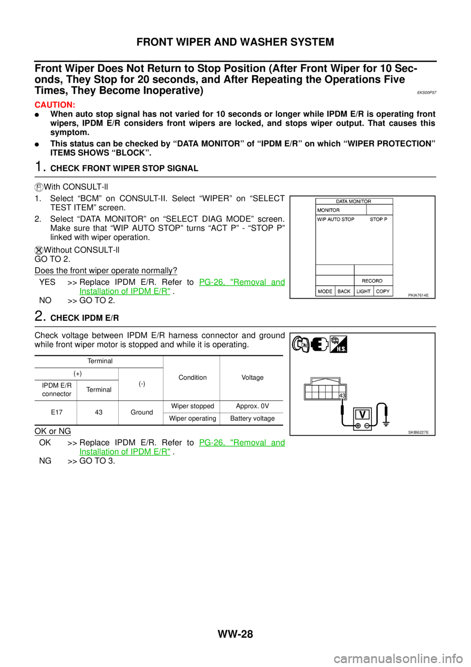
1.CHECK FRONT WIPER STOP SIGNAL
With CONSULT-ll
1. Select “BCM” on CONSULT-II. Select “WIPER” on “SELECT
TEST ITEM” screen.
2. Select “DATA MONITOR” on “SELECT DIAG MODE” screen.
Make sure that “WIP AUTO STOP” turns “ACT P” - “STOP P”
linked with wiper operation.
Without CONSULT-ll
GO TO 2.
Does the front wiper operate normally?
YES >> Replace IPDM E/R. Refer toPG-26, "Removal and
Installation of IPDM E/R".
NO >> GO TO 2.
2.CHECK IPDM E/R
Check voltage between IPDM E/R harness connector and ground
while front wiper motor is stopped and while it is operating.
OK or NG
OK >> Replace IPDM E/R. Refer toPG-26, "Removal and
Installation of IPDM E/R".
NG >> GO TO 3.
PKIA7614E
Terminal
Condition Voltage (+)
(-)
IPDM E/R
connectorTerminal
E17 43 GroundWiper stopped Approx. 0V
Wiper operating Battery voltage
SKIB6227E