Page 85 of 3171

TROUBLE DIAGNOSIS
AT-77
D
E
F
G
H
I
J
K
L
MA
B
AT
CONSULT-II Function (A/T)ECS00FXA
CONSULT-II can display each diagnostic item using the diagnostic test modes shown following.
FUNCTION
CONSULT-II REFERENCE VALUE
NOTICE:
1. The CONSULT-II electrically displays shift timing and lock-up timing (that is, operation timing of each sole-
noid).
Check for time difference between actual shift timing and the CONSULT-II display. If the difference is
noticeable, mechanical parts (except solenoids, sensors, etc.) may be malfunctioning. Check mechanical
parts using applicable diagnostic procedures.
2. Shift schedule (which implies gear position) displayed on CONSULT-II and that indicated in Service Man-
ual may differ slightly. This occurs because of the following reasons:
–Actual shift schedule has more or less tolerance or allowance,
–Shift schedule indicated in Service Manual refers to the point where shifts start, and
–Gear position displayed on CONSULT-II indicates the point where shifts are completed.
3. Display of solenoid valves on CONSULT-II changes at the start of shifting, while gear position is displayed
upon completion of shifting (which is computed by TCM).
Diagnostic test mode Function Reference page
Self-diagnostic results Self-diagnostic results can be read and erased quickly.AT- 8 0
Data monitor Input/Output data in the ECU can be read.AT- 8 3
CAN diagnostic support
monitorThe results of transmit/receive diagnosis of CAN communication can be read.AT- 8 6
Function testConducted by CONSULT-II instead of a technician to determine whether each system
is “OK” or “NG”.—
DTC work support Select the operating condition to confirm Diagnostic Trouble Codes.AT- 8 6
ECU part number ECU part number can be read. —
Item name Condition Display value (Approx.)
VHCL/S SE-A/T
During drivingApproximately matches the speed-
ometer reading.
VHCL/S SE-MTR
ACCELE POSIReleased accelerator pedal. 0.0/8
Fully depressed accelerator pedal. 8.0/8
CLSD THL POSReleased accelerator pedal. ON
Fully depressed accelerator pedal. OFF
W/O THL POSFully depressed accelerator pedal. ON
Released accelerator pedal. OFF
BRAKE SWDepressed brake pedal. ON
Released brake pedal. OFF
ENGINE SPEED Engine runningClosely matches the tachometer
reading.
TURBINE REV During driving (lock-up ON)Approximately matches the engine
speed.
ATFTEMPSE1
0°C(32°F)-20°C(68°F)-80°C (176°F)3.3 - 2.7 - 0.9 V
ATFTEMPSE23.3 - 2.5 - 0.7 V
TCC SOLENOID When perform lock-up 0.4 - 0.6 A
LINE PRES SOL During driving 0.2 - 0.6 A
FR/B SOLENOIDFront brake engaged. Refer toAT- 1 7
. 0.6 - 0.8 A
Front brake disengaged. Refer toAT- 1 7
.0-0.05A
Page 1018 of 3171

EC-38
TROUBLE DIAGNOSIS
Basic Inspection
EBS01KCV
Precaution:
Perform Basic Inspection without electrical or mechanical loads applied;
lHeadlamp switch is OFF.
lOn vehicles equipped with daytime light systems, set lighting switch to the 1st position to light
only small lamps.
lAir conditioner switch is OFF.
lHeater fan switch is OFF.
lRear defogger switch is OFF.
lHeat up switch is OFF.
lSteering wheel is in the straight-ahead position, etc.
1.INSPECTION START
1. Check service records for any recent repairs that may indicate a related incident.
2. Check the current need for scheduled maintenance, especially for fuel filter and air cleaner filter. Refer to
MA-8, "
PERIODIC MAINTENANCE".
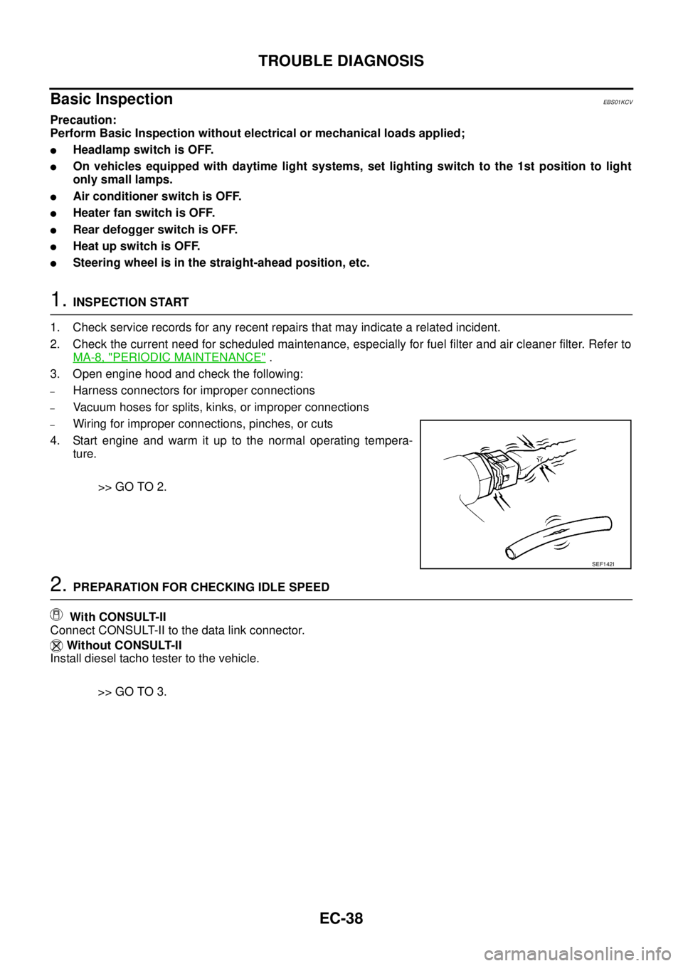
3. Open engine hood and check the following:
–Harness connectors for improper connections
–Vacuum hoses for splits, kinks, or improper connections
–Wiring for improper connections, pinches, or cuts
4. Start engine and warm it up to the normal operating tempera-
ture.
>> GO TO 2.
2.PREPARATION FOR CHECKING IDLE SPEED
With CONSULT-II
Connect CONSULT-II to the data link connector.
Without CONSULT-II
Install diesel tacho tester to the vehicle.
>> GO TO 3.
SEF142I
Page 2309 of 3171

MA-34
CHASSIS AND BODY MAINTENANCE
Changing Rear Final Drive Oil (Rear Differential Gear Oil)
ELS001IW
CAUTION:
If using the vehicle for towing, the final drive oil must be replaced as specified. Refer toMA-8, "
PERI-
ODIC MAINTENANCE".
DRAINING
1. Stop the engine.
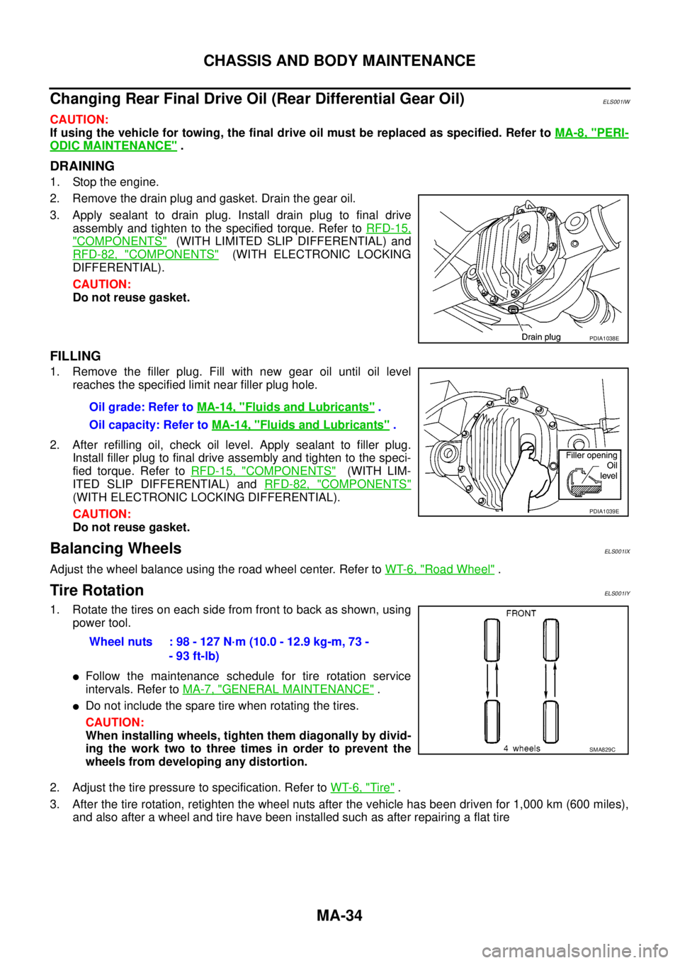
2. Remove the drain plug and gasket. Drain the gear oil.
3. Apply sealant to drain plug. Install drain plug to final drive
assembly and tighten to the specified torque. Refer toRFD-15,
"COMPONENTS"(WITH LIMITED SLIP DIFFERENTIAL) and
RFD-82, "
COMPONENTS"(WITH ELECTRONIC LOCKING
DIFFERENTIAL).
CAUTION:
Do not reuse gasket.
FILLING
1. Remove the filler plug. Fill with new gear oil until oil level
reaches the specified limit near filler plug hole.
2. After refilling oil, check oil level. Apply sealant to filler plug.
Install filler plug to final drive assembly and tighten to the speci-
fied torque. Refer toRFD-15, "
COMPONENTS"(WITH LIM-
ITED SLIP DIFFERENTIAL) andRFD-82, "
COMPONENTS"
(WITH ELECTRONIC LOCKING DIFFERENTIAL).
CAUTION:
Do not reuse gasket.
Balancing WheelsELS001IX
Adjust the wheel balance using the road wheel center. Refer toWT-6, "Road Wheel".
Tire RotationELS001IY
1. Rotate the tires on each side from front to back as shown, using
power tool.
lFollow the maintenance schedule for tire rotation service
intervals. Refer toMA-7, "
GENERAL MAINTENANCE".
lDo not include the spare tire when rotating the tires.
CAUTION:
When installing wheels, tighten them diagonally by divid-
ing the work two to three times in order to prevent the
wheels from developing any distortion.
2. Adjust the tire pressure to specification. Refer toWT-6, "
Tire".
3. After the tire rotation, retighten the wheel nuts after the vehicle has been driven for 1,000 km (600 miles),
and also after a wheel and tire have been installed such as after repairing a flat tire
PDIA1038E
Oil grade: Refer toMA-14, "Fluids and Lubricants".
Oil capacity: Refer toMA-14, "
Fluids and Lubricants".
PDIA1039E
Wheel nuts : 98 - 127 N·m (10.0 - 12.9 kg-m, 73 -
- 93 ft-lb)
SMA829C
Page 3110 of 3171

WHEEL AND TIRE ASSEMBLY
WT-5
C
D
F
G
H
I
J
K
L
MA
B
WT
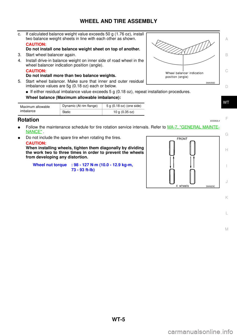
c. If calculated balance weight value exceeds 50 g (1.76 oz), install
two balance weight sheets in line with each other as shown.
CAUTION:
Do not install one balance weight sheet on top of another.
3. Start wheel balancer again.
4. Install drive-in balance weight on inner side of road wheel in the
wheel balancer indication position (angle).
CAUTION:
Do not install more than two balance weights.
5. Start wheel balancer. Make sure that inner and outer residual
imbalance values are 5g (0.18 oz) each or below.
lIf either residual imbalance value exceeds 5 g (0.18 oz), repeat installation procedures.
Wheel balance (Maximum allowable imbalance):
RotationEES002L4
lFollow the maintenance schedule for tire rotation service intervals. Refer toMA-7, "GENERAL MAINTE-
NANCE".
lDo not include the spare tire when rotating the tires.
CAUTION:
When installing wheels, tighten them diagonally by dividing
the work two to three times in order to prevent the wheels
from developing any distortion.
Maximum allowable
imbalanceDynamic (At rim flange) 5 g (0.18 oz) (one side)
Static 10 g (0.35 oz)
SMA056D
Wheel nut torque : 98 - 127 N·m (10.0 - 12.9 kg-m,
73 - 93 ft-lb)
SMA829C