2005 NISSAN NAVARA service indicator
[x] Cancel search: service indicatorPage 990 of 3171

EC-10
PRECAUTIONS
PRECAUTIONS
PFP:00001
Precautions for Supplemental Restraint System (SRS) “AIR BAG” and “SEAT
BELT PRE-TENSIONER”
EBS01KC5
The Supplemental Restraint System such as “AIR BAG” and “SEAT BELT PRE-TENSIONER”, used along
with a front seat belt, helps to reduce the risk or severity of injury to the driver and front passenger for certain
types of collision. Information necessary to service the system safely is included in the SRS and SB section of
this Service Manual.
WARNING:
lTo avoid rendering the SRS inoperative, which could increase the risk of personal injury or death
in the event of a collision which would result in air bag inflation, all maintenance must be per-
formed by an authorized NISSAN/INFINITI dealer.
lImproper maintenance, including incorrect removal and installation of the SRS, can lead to per-
sonal injury caused by unintentional activation of the system. For removal of Spiral Cable and Air
Bag Module, see the SRS section.
lDo not use electrical test equipment on any circuit related to the SRS unless instructed to in this
Service Manual. SRS wiring harnesses can be identified by yellow and/or orange harnesses or
harness connectors.
On Board Diagnostic (OBD) System of EngineEBS01KC6
The ECM has an on board diagnostic system. It will light up the malfunction indicator (MI) to warn the driver of
a malfunction causing emission deterioration.
CAUTION:
lBe sure to turn the ignition switch OFF and disconnect the battery negative cable before any
repair or inspection work. The open/short circuit of related switches, sensors, solenoid valves,
etc. will cause the MI to light up.
lBe sure to connect and lock the connectors securely after work. A loose (unlocked) connector will
cause the MI to light up due to the open circuit. (Be sure the connector is free from water, grease,
dirt, bent terminals, etc.)
lCertain systems and components, especially those related to OBD, may use a new style slide-
locking type harness connector. For description and how to disconnect, refer toPG-75, "
HAR-
NESS CONNECTOR".
lBe sure to route and secure the harnesses properly after work. The interference of the harness
with a bracket, etc. may cause the MI to light up due to the short circuit.
lBe sure to connect rubber tubes properly after work. A misconnected or disconnected rubber tube
may cause the MI to light up due to the malfunction of the fuel system, etc.
lBe sure to erase the unnecessary malfunction information (repairs completed) from the ECM
before returning the vehicle to the customer.
PrecautionsEBS01KC7
lAlways use a 12 volt battery as power source.
lDo not attempt to disconnect battery cables while engine is
running.
lBefore connecting or disconnecting the ECM harness con-
nector, turn ignition switch OFF and disconnect battery
negative cable. Failure to do so may damage the ECM
because battery voltage is applied to ECM even if ignition
switch is turned off.
lBefore removing parts, turn ignition switch OFF and then
disconnect battery negative cable.
SEF289H
Page 1522 of 3171
EM-140
SERVICE DATA AND SPECIFICATIONS (SDS)
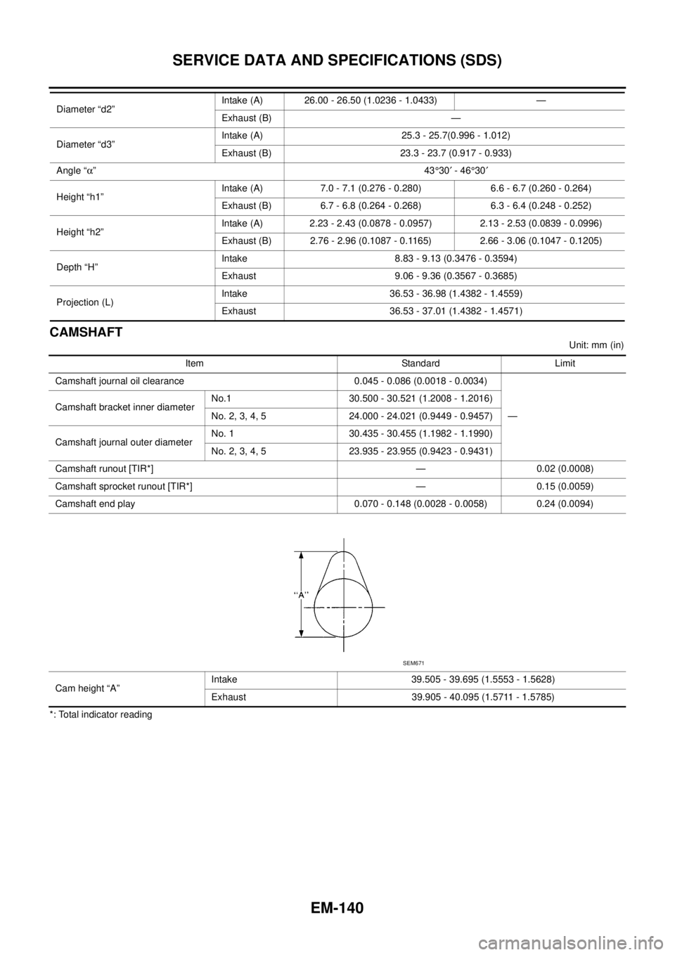
CAMSHAFT
Unit: mm (in)
*: Total indicator readingDiameter “d2”Intake (A) 26.00 - 26.50 (1.0236 - 1.0433) —
Exhaust (B) —
Diameter “d3”Intake (A) 25.3 - 25.7(0.996 - 1.012)
Exhaust (B) 23.3 - 23.7 (0.917 - 0.933)
Angle “a”43°30¢-46°30¢
Height “h1”Intake (A) 7.0 - 7.1 (0.276 - 0.280) 6.6 - 6.7 (0.260 - 0.264)
Exhaust (B) 6.7 - 6.8 (0.264 - 0.268) 6.3 - 6.4 (0.248 - 0.252)
Height “h2”Intake (A) 2.23 - 2.43 (0.0878 - 0.0957) 2.13 - 2.53 (0.0839 - 0.0996)
Exhaust (B) 2.76 - 2.96 (0.1087 - 0.1165) 2.66 - 3.06 (0.1047 - 0.1205)
Depth “H”Intake 8.83 - 9.13 (0.3476 - 0.3594)
Exhaust 9.06 - 9.36 (0.3567 - 0.3685)
Projection (L)Intake 36.53 - 36.98 (1.4382 - 1.4559)
Exhaust 36.53 - 37.01 (1.4382 - 1.4571)
Item Standard Limit
Camshaft journal oil clearance 0.045 - 0.086 (0.0018 - 0.0034)
— Camshaft bracket inner diameterNo.1 30.500 - 30.521 (1.2008 - 1.2016)
No. 2, 3, 4, 5 24.000 - 24.021 (0.9449 - 0.9457)
Camshaft journal outer diameterNo. 1 30.435 - 30.455 (1.1982 - 1.1990)
No. 2, 3, 4, 5 23.935 - 23.955 (0.9423 - 0.9431)
Camshaft runout [TIR*] — 0.02 (0.0008)
Camshaft sprocket runout [TIR*] — 0.15 (0.0059)
Camshaft end play 0.070 - 0.148 (0.0028 - 0.0058) 0.24 (0.0094)
Cam height “A”Intake 39.505 - 39.695 (1.5553 - 1.5628)
Exhaust 39.905 - 40.095 (1.5711 - 1.5785)
SEM671
Page 1526 of 3171
EM-144
SERVICE DATA AND SPECIFICATIONS (SDS)
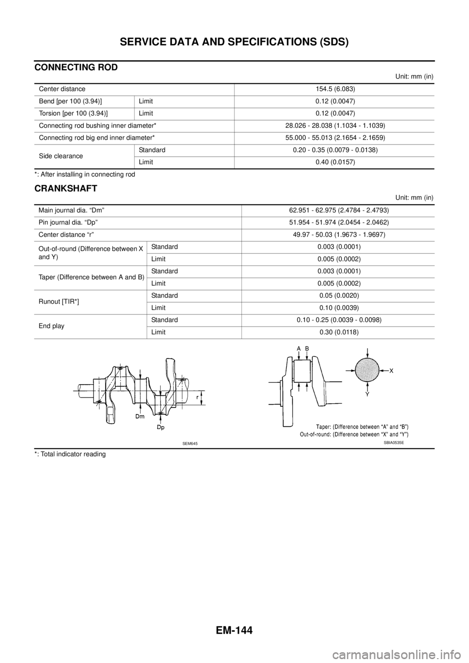
CONNECTING ROD
Unit: mm (in)
*: After installing in connecting rod
CRANKSHAFT
Unit: mm (in)
*: Total indicator readingCenter distance154.5 (6.083)
Bend [per 100 (3.94)] Limit 0.12 (0.0047)
Torsion [per 100 (3.94)] Limit 0.12 (0.0047)
Connecting rod bushing inner diameter* 28.026 - 28.038 (1.1034 - 1.1039)
Connecting rod big end inner diameter* 55.000 - 55.013 (2.1654 - 2.1659)
Side clearanceStandard 0.20 - 0.35 (0.0079 - 0.0138)
Limit 0.40 (0.0157)
Main journal dia. “Dm” 62.951 - 62.975 (2.4784 - 2.4793)
Pin journal dia. “Dp” 51.954 - 51.974 (2.0454 - 2.0462)
Center distance “r” 49.97 - 50.03 (1.9673 - 1.9697)
Out-of-round (Difference between X
and Y)Standard 0.003 (0.0001)
Limit 0.005 (0.0002)
Taper (Difference between A and B)Standard 0.003 (0.0001)
Limit 0.005 (0.0002)
Runout [TIR*]Standard 0.05 (0.0020)
Limit 0.10 (0.0039)
End playStandard 0.10 - 0.25 (0.0039 - 0.0098)
Limit 0.30 (0.0118)
SEM645SBIA0535E
Page 1527 of 3171
SERVICE DATA AND SPECIFICATIONS (SDS)
EM-145
C
D
E
F
G
H
I
J
K
L
MA
EM
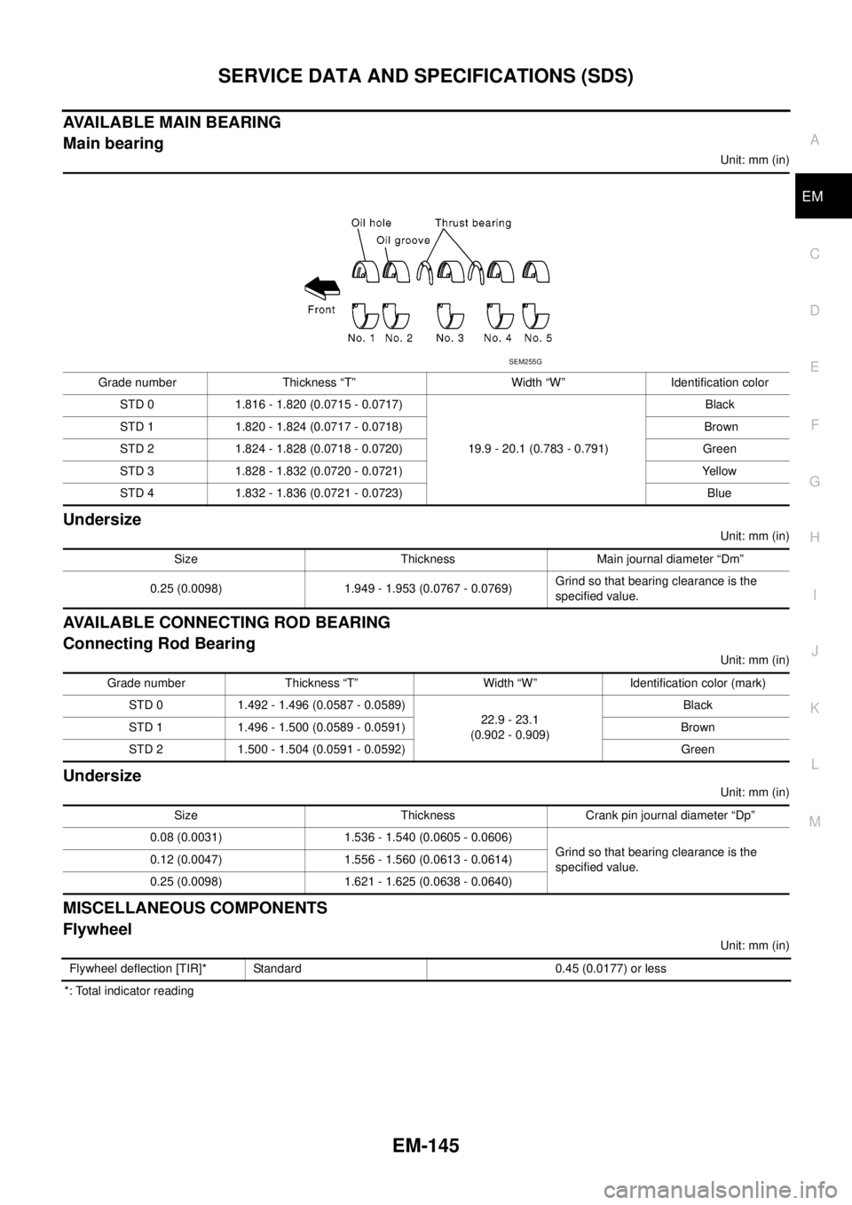
AVAILABLE MAIN BEARING
Main bearing
Unit: mm (in)
Undersize
Unit: mm (in)
AVAILABLE CONNECTING ROD BEARING
Connecting Rod Bearing
Unit: mm (in)
Undersize
Unit: mm (in)
MISCELLANEOUS COMPONENTS
Flywheel
Unit: mm (in)
*: Total indicator readingGrade number Thickness “T” Width “W” Identification color
STD 0 1.816 - 1.820 (0.0715 - 0.0717)
19.9 - 20.1 (0.783 - 0.791)Black
STD 1 1.820 - 1.824 (0.0717 - 0.0718) Brown
STD 2 1.824 - 1.828 (0.0718 - 0.0720) Green
STD 3 1.828 - 1.832 (0.0720 - 0.0721) Yellow
STD 4 1.832 - 1.836 (0.0721 - 0.0723) Blue
SEM255G
Size Thickness Main journal diameter “Dm”
0.25 (0.0098) 1.949 - 1.953 (0.0767 - 0.0769)Grind so that bearing clearance is the
specified value.
Grade number Thickness “T” Width “W” Identification color (mark)
STD 0 1.492 - 1.496 (0.0587 - 0.0589)
22.9 - 23.1
(0.902 - 0.909)Black
STD 1 1.496 - 1.500 (0.0589 - 0.0591) Brown
STD 2 1.500 - 1.504 (0.0591 - 0.0592) Green
Size Thickness Crank pin journal diameter “Dp”
0.08 (0.0031) 1.536 - 1.540 (0.0605 - 0.0606)
Grind so that bearing clearance is the
specified value. 0.12 (0.0047) 1.556 - 1.560 (0.0613 - 0.0614)
0.25 (0.0098) 1.621 - 1.625 (0.0638 - 0.0640)
Flywheel deflection [TIR]* Standard 0.45 (0.0177) or less
Page 1625 of 3171
PRECAUTIONS
GI-3
C
D
E
F
G
H
I
J
K
L
MB
GI
PRECAUTIONSPFP:00001
DescriptionEAS001GG
Observe the following precautions to ensure safe and proper servicing. These precautions are not
described in each individual section.
Precautions for Supplemental Restraint System (SRS) “AIR BAG” and “SEAT
BELT PRE-TENSIONER”
EAS001GH
The Supplemental Restraint System such as “AIR BAG” and “SEAT BELT PRE-TENSIONER”, used along
with a front seat belt, helps to reduce the risk or severity of injury to the driver and front passenger for certain
types of collision. Information necessary to service the system safely is included in the SRS and SB section of
this Service Manual.
WARNING:
lTo avoid rendering the SRS inoperative, which could increase the risk of personal injury or death
in the event of a collision which would result in air bag inflation, all maintenance must be per-
formed by an authorized NISSAN/INFINITI dealer.
lImproper maintenance, including incorrect removal and installation of the SRS, can lead to per-
sonal injury caused by unintentional activation of the system. For removal of Spiral Cable and Air
Bag Module, see the SRS section.
lDo not use electrical test equipment on any circuit related to the SRS unless instructed to in this
Service Manual. SRS wiring harnesses can be identified by yellow and/or orange harnesses or
harness connectors.
Precautions for NATS (NISSAN ANTI-THEFT SYSTEM)EAS001GI
NATS will immobilize the engine if someone tries to start it without the registered key of NATS.
Both of the originally supplied ignition key IDs have been NATS registered.
The security indicator is located on the instrument panel. The indicator blinks when the immobilizer system is
functioning.
Therefore, NATS warns outsiders that the vehicle is equipped with the anti-theft system.
lWhen NATS detects trouble, the security indicator lamp lights up while ignition switch is in "ON" position.
This lighting up indicates that the anti-theft is not functioning, so prompt service is required.
lWhen servicing NATS (trouble diagnoses, system initialization and additional registration of other NATS
ignition key IDs), CONSULT-II hardware and CONSULT-II NATS software is necessary.
Regarding the procedures of NATS initialization and NATS ignition key ID registration, refer to CONSULT-
II operation manual, NATS.
Therefore, CONSULT-II NATS software (program card and operation manual) must be kept strictly con-
fidential to maintain the integrity of the anti-theft function.
lWhen servicing NATS (trouble diagnoses, system initialization and additional registration of other NATS
ignition key IDs), it may be necessary to re-register original key identification. Therefore, be sure to
receive all keys from vehicle owner. A maximum of four or five key IDs can be registered into NATS.
lWhen failing to start the engine first time using the key of NATS, start as follows.
1. Leave the ignition key in "ON" position for approximately 5 seconds.
2. Turn ignition key to "OFF" or "LOCK" position and wait approximately 5 seconds.
3. Repeat step 1 and 2 again.
4. Restart the engine while keeping the key separate from any others on key-chain.
Precautions Necessary for Steering Wheel Rotation After Battery DisconnectEAS001HY
NOTE:
lThis Procedure is applied only to models with Intelligent Key system and NATS (NISSAN ANTI-THEFT
SYSTEM).
lRemove and install all control units after disconnecting both battery cables with the ignition knob in the
²LOCK²position.
lAlways use CONSULT-II to perform self-diagnosis as a part of each function inspection after finishing
work. If DTC is detected, perform trouble diagnosis according to self-diagnostic results.
For models equipped with the Intelligent Key system and NATS, an electrically controlled steering lock mech-
anism is adopted on the key cylinder.
Page 1685 of 3171

TERMINOLOGY
GI-63
C
D
E
F
G
H
I
J
K
L
MB
GI
Nonvolatile random access memory NVRAM ***
On board diagnostic system OBD system Self-diagnosis
Open loop OL Open loop
Oxidation catalyst OC Catalyst
Oxidation catalytic converter system OC system ***
Oxygen sensor O2S Exhaust gas sensor
Park position switch *** Park switch
Park/neutral position switch PNP switchPark/neutral switch
Inhibitor switch
Neutral position switch
Periodic trap oxidizer system PTOX system ***
Positive crankcase ventilation PCV Positive crankcase ventilation
Positive crankcase ventilation valve PCV valve PCV valve
Powertrain control module PCM ***
Programmable read only memory PROM ***
Pulsed secondary air injection control sole-
noid valvePAIRC solenoid valve AIV control solenoid valve
Pulsed secondary air injection system PAIR system Air induction valve (AIV) control
Pulsed secondary air injection valve PAIR valve Air induction valve
Random access memory RAM ***
Read only memory ROM ***
Scan tool ST ***
Secondary air injection pump AIR pump ***
Secondary air injection system AIR system ***
Sequential multiport fuel injection system SFI system Sequential fuel injection
Service reminder indicator SRI ***
Simultaneous multiport fuel injection sys-
tem*** Simultaneous fuel injection
Smoke puff limiter system SPL system ***
Supercharger SC ***
Supercharger bypass SCB ***
System readiness test SRT ***
Thermal vacuum valve TVV Thermal vacuum valve
Three way catalyst TWC Catalyst
Three way catalytic converter system TWC system ***
Three way + oxidation catalyst TWC + OC Catalyst
Three way + oxidation catalytic converter
systemTWC + OC system ***
Throttle body TBThrottle chamber
SPI body
Throttle body fuel injection system TBI system Fuel injection control
Throttle position TP Throttle position
Throttle position sensor TPS Throttle sensor
Throttle position switch TP switch Throttle switch
Torque converter clutch solenoid valve TCC solenoid valveLock-up cancel solenoid
Lock-up solenoid NEW TERMNEW ACRONYM /
ABBREVIATIONOLD TERM
Page 1754 of 3171
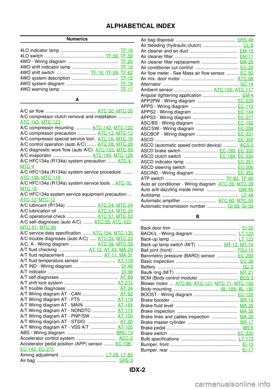
IDX-2
ALPHABETICAL INDEX
Numerics
4LO indicator lamp .............................................TF-16
4LO switch ..............................................TF-56,TF-59
4WD - Wiring diagram .......................................TF-25
4WD shift indicator lamp ....................................TF-16
4WD shift switch .........................TF-16,TF-59,TF-62
4WD system description ....................................TF-15
4WD system diagram ........................................TF-18
4WD warning lamp ............................................TF-17
A
A/C air flow .......................................ATC-30
,MTC-30
A/C compressor clutch removal and installation ...........
ATC-143
,MTC-123
A/C compressor mounting ............ATC-142,MTC-122
A/C compressor precaution ..............ATC-12,MTC-12
A/C compressor special service tool .ATC-16,MTC-16
A/C control operation (auto A/C) .......ATC-28,MTC-28
A/C diagnostic work flow (auto A/C)ATC-103,MTC-95
A/C evaporator ..............................ATC-149,MTC-129
A/C HFC134a (R134a) system precaution .......ATC-4,
MTC-4
A/C HFC134a (R134a) system service procedure .......
ATC-138
,MTC-118
A/C HFC134a (R134a) system service tools ..ATC-16,
MTC-16
A/C HFC134a system service equipment precaution ...
ATC-12
,MTC-12
A/C lubricant (R134a) .......................ATC-24,MTC-24
A/C lubrication oil ..............................ATC-24,MTC-24
A/C operational check .......................ATC-57,MTC-53
A/C self-diagnoses (auto A/C) .......ATC-55,ATC-103,
MTC-51
,MTC-95
A/C service data specification .......ATC-154,MTC-135
A/C trouble diagnoses (auto A/C) .....ATC-33,MTC-33
A/C, A - Wiring diagram ....................ATC-39,MTC-39
A/T fluid checking ......................AT-12,AT-43,MA-29
A/T fluid replacement .............................AT-11,MA-31
A/T fluid temperature sensor ...........................AT-118
A/T IND - Wiring diagram ....................................DI-49
A/T indicator ........................................................DI-48
A/T self-diagnoses .............................................AT-89
A/T shift lock system ........................................AT-212
A/T trouble diagnoses ........................................AT-34
A/T Wiring diagram AT - CAN ............................AT-92
A/T Wiring diagram AT - FTS ..........................AT-119
A/T Wiring diagram AT - MAIN ........................AT-164
A/T Wiring diagram AT - NONDTC ..................AT-174
A/T Wiring diagram AT - PNP/SW ...................AT-100
A/T Wiring diagram AT - STSIG ........................AT-95
A/T Wiring diagram AT - VSS A/T ...................AT-105
ABS - Wiring diagram .....................................BRC-13
Accelerator control system ...............................ACC-2
Accelerator pedal position (APP) sensor ........EC-108,
EC-142
,EC-275
Aiming adjustment ..................................LT-28,LT-85
Air bag ..............................................................SRS-3
Air bag disposal ..............................................SRS-49
Air bleeding (hydraulic clutch) ..............................CL-8
Air cleaner and air duct .....................................EM-15
Air cleaner filter .................................................EM-17
Air cleaner filter replacement ............................MA-25
Air conditioner cut control ..................................EC-20
Air flow meter - See Mass air flow sensor ..........EC-92
Air mix. door motor .........................................ATC-68
Alternator ...........................................................SC-14
Ambient sensor .............................ATC-105,ATC-117
Angular tightening application .............................EM-4
APP2PW - Wiring diagram ..............................EC-229
APPS - Wiring diagram ....................................EC-110
APPS2 - Wiring diagram ..................................EC-144
APPS3 - Wiring diagram ..................................EC-277
ASC/BS - Wiring diagram ................................EC-192
ASC/SW - Wiring diagram ...............................EC-208
ASCBOF - Wiring diagram ...............................EC-331
ASCD ...............................................................EC-355
ASCD (automatic speed control device) ...........ACS-2
ASCD brake switch ...........................EC-189,EC-330
ASCD clutch switch ..........................EC-189,EC-330
ASCD indicator lamp .......................................EC-351
ASCD steering switch ......................................EC-206
ASCIND - Wiring diagram ................................EC-352
ATP switch ..............................................TF-82,TF-85
Auto air conditioner - Wiring diagramATC-39,MTC-39
Auto anti-dazzling inside mirror .......................GW-45
Autolamp ............................................................LT-49
Automatic amplifier ..........................ATC-60,MTC-55
Automatic transmission number ..............GI-58,GI-59
B
Back door trim .....................................................EI-30
BACK/L - Wiring diagram .................................LT-123
Back-up lamp ...................................................LT-123
Back-up lamp switch (M/T) ...................MT-12,MT-19
Ball joint (front) ................................................FSU-15
Barometric pressure (BARO) sensor ...............EC-293
Basic inspection .................................................EC-38
Battery .................................................................SC-5
Baulk ring (M/T) ................................................MT-21
BCM (Body control module) ..............................BCS-3
Blower motor ...ATC-80,ATC-121,MTC-71,MTC-100
Body mounting ....................................BL-189,BL-190
BOOST - Wiring diagram .................................EC-155
Brake booster ....................................................BR-19
Brake fluid level ................................................MA-35
Brake inspection ...............................................MA-35
Brake lines and cables inspection ....................MA-35
Brake master cylinder ........................................BR-17
Brake pedal ..........................................................BR-6
Brake switch ....................................................EC-330
Bulb specifications ...........................................LT-173
Bumper, front ......................................................EI-15
Bumper, rear .......................................................EI-17
Page 2084 of 3171
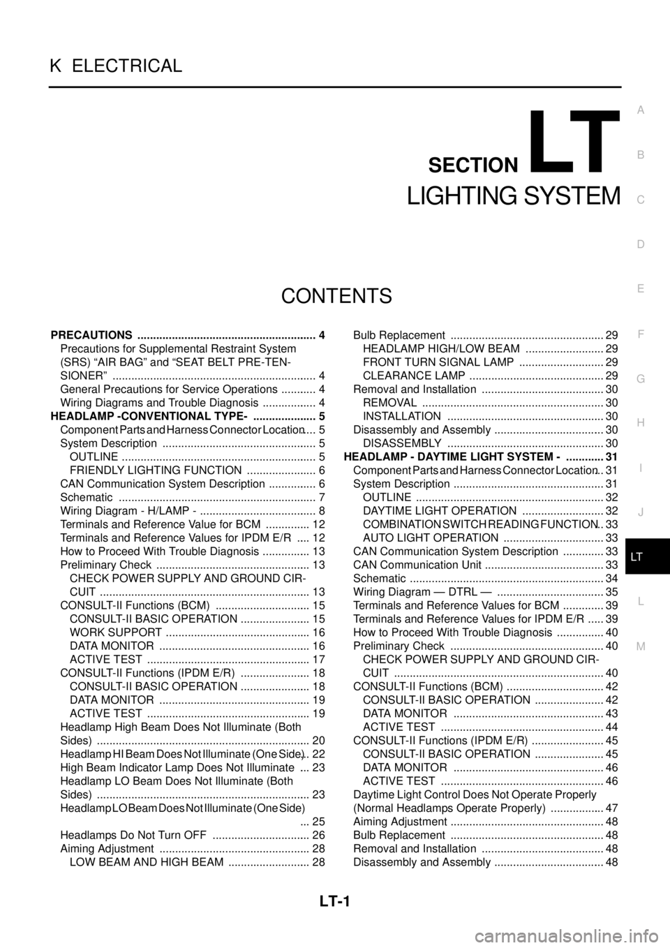
LT-1
LIGHTING SYSTEM
K ELECTRICAL
CONTENTS
C
D
E
F
G
H
I
J
L
M
SECTIONLT
A
B
LT
LIGHTING SYSTEM
PRECAUTIONS .......................................................... 4
Precautions for Supplemental Restraint System
(SRS)“AIRBAG”and“SEATBELTPRE-TEN-
SIONER” .................................................................. 4
General Precautions for Service Operations ............ 4
Wiring Diagrams and Trouble Diagnosis .................. 4
HEADLAMP -CONVENTIONAL TYPE- ..................... 5
Component Parts and Harness Connector Location..... 5
System Description .................................................. 5
OUTLINE ............................................................... 5
FRIENDLY LIGHTING FUNCTION ....................... 6
CAN Communication System Description ................ 6
Schematic ................................................................ 7
Wiring Diagram - H/LAMP - ...................................... 8
Terminals and Reference Value for BCM ............... 12
Terminals and Reference Values for IPDM E/R ..... 12
How to Proceed With Trouble Diagnosis ................ 13
Preliminary Check .................................................. 13
CHECK POWER SUPPLY AND GROUND CIR-
CUIT .................................................................... 13
CONSULT-II Functions (BCM) ............................... 15
CONSULT-II BASIC OPERATION ....................... 15
WORK SUPPORT ............................................... 16
DATA MONITOR ................................................. 16
ACTIVE TEST ..................................................... 17
CONSULT-II Functions (IPDM E/R) ....................... 18
CONSULT-II BASIC OPERATION ....................... 18
DATA MONITOR ................................................. 19
ACTIVE TEST ..................................................... 19
Headlamp High Beam Does Not Illuminate (Both
Sides) ..................................................................... 20
Headlamp HI Beam Does Not Illuminate (One Side)... 22
High Beam Indicator Lamp Does Not Illuminate .... 23
Headlamp LO Beam Does Not Illuminate (Both
Sides) ..................................................................... 23
Headlamp LO Beam Does Not Illuminate (One Side)
... 25
Headlamps Do Not Turn OFF ................................ 26
Aiming Adjustment ................................................. 28
LOW BEAM AND HIGH BEAM ........................... 28Bulb Replacement .................................................. 29
HEADLAMP HIGH/LOW BEAM .......................... 29
FRONT TURN SIGNAL LAMP ............................ 29
CLEARANCE LAMP ............................................ 29
Removal and Installation ........................................ 30
REMOVAL ........................................................... 30
INSTALLATION ................................................... 30
Disassembly and Assembly .................................... 30
DISASSEMBLY ................................................... 30
HEADLAMP - DAYTIME LIGHT SYSTEM - ............. 31
Component Parts and Harness Connector Location... 31
System Description ................................................. 31
OUTLINE ............................................................. 32
DAYTIME LIGHT OPERATION ........................... 32
COMBINATION SWITCH READING FUNCTION... 33
AUTO LIGHT OPERATION ................................. 33
CAN Communication System Description .............. 33
CAN Communication Unit ....................................... 33
Schematic ............................................................... 34
Wiring Diagram — DTRL — ................................... 35
Terminals and Reference Values for BCM .............. 39
Terminals and Reference Values for IPDM E/R ...... 39
How to Proceed With Trouble Diagnosis ................ 40
Preliminary Check .................................................. 40
CHECK POWER SUPPLY AND GROUND CIR-
CUIT .................................................................... 40
CONSULT-II Functions (BCM) ................................ 42
CONSULT-II BASIC OPERATION ....................... 42
DATA MONITOR ................................................. 43
ACTIVE TEST ..................................................... 44
CONSULT-II Functions (IPDM E/R) ........................ 45
CONSULT-II BASIC OPERATION ....................... 45
DATA MONITOR ................................................. 46
ACTIVE TEST ..................................................... 46
Daytime Light Control Does Not Operate Properly
(Normal Headlamps Operate Properly) .................. 47
Aiming Adjustment .................................................. 48
Bulb Replacement .................................................. 48
Removal and Installation ........................................ 48
Disassembly and Assembly .................................... 48