2005 NISSAN NAVARA service indicator
[x] Cancel search: service indicatorPage 2704 of 3171
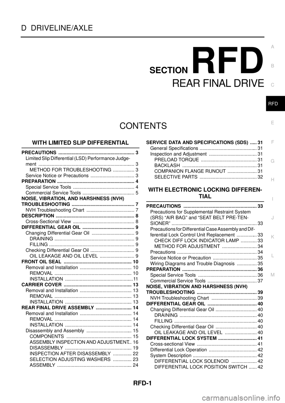
RFD-1
REAR FINAL DRIVE
D DRIVELINE/AXLE
CONTENTS
C
E
F
G
H
I
J
K
L
M
SECTIONRFD
A
B
RFD
REAR FINAL DRIVE
WITH LIMITED SLIP DIFFERENTIAL
PRECAUTIONS .......................................................... 3
Limited Slip Differential (LSD) Performance Judge-
ment ......................................................................... 3
METHOD FOR TROUBLESHOOTING ................. 3
Service Notice or Precautions .................................. 3
PREPARATION ........................................................... 4
Special Service Tools ............................................... 4
Commercial Service Tools ........................................ 5
NOISE, VIBRATION, AND HARSHNESS (NVH)
TROUBLESHOOTING ................................................ 7
NVH Troubleshooting Chart ..................................... 7
DESCRIPTION ............................................................ 8
Cross-Sectional View ............................................... 8
DIFFERENTIAL GEAR OIL ........................................ 9
Changing Differential Gear Oil ................................. 9
DRAINING ............................................................. 9
FILLING ................................................................. 9
Checking Differential Gear Oil .................................. 9
OIL LEAKAGE AND OIL LEVEL ........................... 9
FRONT OIL SEAL .................................................... 10
Removal and Installation ........................................ 10
REMOVAL ........................................................... 10
INSTALLATION .................................................... 11
CARRIER COVER .................................................... 13
Removal and Installation ........................................ 13
REMOVAL ........................................................... 13
INSTALLATION ................................................... 13
REAR FINAL DRIVE ASSEMBLY ............................ 14
Removal and Installation ........................................ 14
REMOVAL ........................................................... 14
INSTALLATION ................................................... 14
Disassembly and Assembly ................................... 15
COMPONENTS .................................................. 15
ASSEMBLY INSPECTION AND ADJUSTMENT... 16
DISASSEMBLY ................................................... 19
INSPECTION AFTER DISASSEMBLY ............... 22
SELECTION ADJUSTING WASHERS ............... 23
ASSEMBLY ......................................................... 24SERVICE DATA AND SPECIFICATIONS (SDS) ...... 31
General Specifications ............................................ 31
Inspection and Adjustment ..................................... 31
PRELOAD TORQUE ........................................... 31
BACKLASH ......................................................... 31
COMPANION FLANGE RUNOUT ....................... 31
SELECTIVE PARTS ............................................ 32
WITH ELECTRONIC LOCKING DIFFEREN-
TIAL
PRECAUTIONS ........................................................ 33
Precautions for Supplemental Restraint System
(SRS)“AIRBAG”and“SEATBELTPRE-TEN-
SIONER” ................................................................. 33
Precautions for Differential Case Assembly and Dif-
ferential Lock Control Unit Replacement ................ 33
CHECK DIFF LOCK INDICATOR LAMP ............. 33
METHOD FOR ADJUSTMENT ........................... 34
Precautions ............................................................. 34
Service Notice or Precaution .................................. 35
Wiring Diagrams and Trouble Diagnosis ................ 35
PREPARATION ......................................................... 36
Special Service Tools ............................................. 36
Commercial Service Tools ...................................... 37
NOISE, VIBRATION AND HARSHNESS (NVH)
TROUBLESHOOTING .............................................. 39
NVH Troubleshooting Chart ................................... 39
DIFFERENTIAL GEAR OIL ...................................... 40
Changing Differential Gear Oil ................................ 40
DRAINING ........................................................... 40
FILLING ............................................................... 40
Checking Differential Gear Oil ................................ 40
OIL LEAKAGE AND OIL LEVEL ......................... 40
DIFFERENTIAL LOCK SYSTEM .............................. 41
Cross-sectional View .............................................. 41
Differential Lock Operation ..................................... 42
System Description ................................................. 42
DIFFERENTIAL LOCK SOLENOID .................... 42
DIFFERENTIAL LOCK POSITION SWITCH ....... 42
Page 2705 of 3171

RFD-2
DIFFERENTIAL LOCK CONTROL UNIT ............ 42
DIFFERENTIAL LOCK MODE SWITCH ............. 42
DIFF LOCK INDICATOR LAMP ........................... 42
System Diagram ..................................................... 43
COMPONENTS FUNCTION DESCRIPTION ...... 43
CAN Communication .............................................. 43
SYSTEM DESCRIPTION .................................... 43
TROUBLE DIAGNOSIS ............................................ 44
Fail-safe Function ................................................... 44
How to Perform Trouble Diagnosis ......................... 44
BASIC CONCEPT ............................................... 44
Location of Electrical Parts ..................................... 45
Wiring Diagram — DIFLOC — ................................ 46
Trouble Diagnosis Chart for Symptoms .................. 48
Differential Lock Control Unit Input/Output Signal
Reference Values ................................................... 48
DIFFERENTIAL LOCK CONTROL UNIT
INSPECTION TABLE .......................................... 48
CONSULT-II Function (DIFF LOCK) ....................... 50
FUNCTION .......................................................... 50
CONSULT-II SETTING PROCEDURE ................ 50
SELF-DIAG RESULTS MODE ............................. 51
DATA MONITOR MODE ...................................... 53
TROUBLE DIAGNOSIS FOR SYSTEM .................... 54
Power Supply Circuit For Differential Lock Control
Unit ......................................................................... 54
CONSULT-II REFERENCE VALUE IN DATA
MONITOR MODE ................................................ 54
DIFFERENTIAL LOCK CONTROL UNIT TER-
MINALS AND REFERENCE VALUE ................... 54
DIAGNOSTIC PROCEDURE .............................. 55
Differential Lock Control Unit .................................. 56
DIAGNOSTIC PROCEDURE .............................. 56
Differential Lock Mode Switch ................................ 56
CONSULT-II REFERENCE VALUE IN DATA
MONITOR MODE ................................................ 56
DIFFERENTIAL LOCK CONTROL UNIT TER-
MINALS AND REFERENCE VALUE ................... 56
DIAGNOSTIC PROCEDURE .............................. 57
COMPONENT INSPECTION .............................. 59
Differential Lock Position Switch ............................. 60
CONSULT-II REFERENCE VALUE IN DATA
MONITOR MODE ................................................ 60
DIFFERENTIAL CONTROL UNIT TERMINALS
AND REFERENCE VALUE ................................. 60
DIAGNOSTIC PROCEDURE .............................. 61
COMPONENT INSPECTION .............................. 63
Differential Lock Solenoid Relay ............................. 63
CONSULT-II REFERENCE VALUE IN DATA
MONITOR MODE ................................................ 63DIAGNOSTIC PROCEDURE ............................... 63
Differential Lock Solenoid ....................................... 64
CONSULT-II REFERENCE VALUE IN DATA
MONITOR MODE ................................................ 64
DIFFERENTIAL LOCK CONTROL UNIT TER-
MINALS AND REFERENCE VALUE ................... 64
DIAGNOSTIC PROCEDURE ............................... 65
COMPONENT INSPECTION ............................... 68
ABS System ............................................................ 68
DIAGNOSTIC PROCEDURE ............................... 68
CAN Communication Line ....................................... 69
DIAGNOSTIC PROCEDURE ............................... 69
TROUBLE DIAGNOSIS FOR SYMPTOMS .............. 70
DIFF LOCK Indicator Lamp Does Not Turn ON ...... 70
DIAGNOSTIC PROCEDURE ............................... 70
DIFF LOCK Indicator Lamp Does Not Change ....... 73
DIAGNOSTIC PROCEDURE ............................... 73
DIFF LOCK Indicator Lamp Sometimes Flashes .... 74
DIAGNOSTIC PROCEDURE ............................... 74
DIFFERENTIAL LOCK CONTROL UNIT .................. 76
Removal and Installation ......................................... 76
REMOVAL ............................................................ 76
INSTALLATION .................................................... 76
FRONT OIL SEAL ..................................................... 77
Removal and Installation ......................................... 77
REMOVAL ............................................................ 77
INSTALLATION .................................................... 78
CARRIER COVER ..................................................... 80
Removal and Installation ......................................... 80
REMOVAL ............................................................ 80
INSTALLATION .................................................... 80
REAR FINAL DRIVE ASSEMBLY ............................. 81
Removal and Installation ......................................... 81
REMOVAL ............................................................ 81
INSTALLATION .................................................... 81
Disassembly and Assembly .................................... 82
COMPONENTS ................................................... 82
ASSEMBLY INSPECTION AND ADJUSTMENT...83
DISASSEMBLY .................................................... 86
INSPECTION AFTER DISASSEMBLY ................ 90
SELECTION ADJUSTING WASHERS ................ 90
ASSEMBLY .......................................................... 91
SERVICE DATA AND SPECIFICATIONS (SDS) ....100
General Specifications ..........................................100
Inspection and Adjustment ....................................100
PRELOAD TORQUE .........................................100
BACKLASH ........................................................100
COMPANION FLANGE RUNOUT .....................100
SELECTIVE PARTS ..........................................101
Page 2736 of 3171
![NISSAN NAVARA 2005 Repair Workshop Manual PRECAUTIONS
RFD-33
[WITH ELECTRONIC LOCKING DIFFERENTIAL]
C
E
F
G
H
I
J
K
L
MA
B
RFD
[WITH ELECTRONIC LOCKING DIFFERENTIAL]PRECAUTIONSPFP:00001
Precautions for Supplemental Restraint System (SRS) “A NISSAN NAVARA 2005 Repair Workshop Manual PRECAUTIONS
RFD-33
[WITH ELECTRONIC LOCKING DIFFERENTIAL]
C
E
F
G
H
I
J
K
L
MA
B
RFD
[WITH ELECTRONIC LOCKING DIFFERENTIAL]PRECAUTIONSPFP:00001
Precautions for Supplemental Restraint System (SRS) “A](/manual-img/5/57362/w960_57362-2735.png)
PRECAUTIONS
RFD-33
[WITH ELECTRONIC LOCKING DIFFERENTIAL]
C
E
F
G
H
I
J
K
L
MA
B
RFD
[WITH ELECTRONIC LOCKING DIFFERENTIAL]PRECAUTIONSPFP:00001
Precautions for Supplemental Restraint System (SRS) “AIR BAG” and “SEAT
BELT PRE-TENSIONER”
EDS003IE
The Supplemental Restraint System such as “AIR BAG” and “SEAT BELT PRE-TENSIONER”, used along
with a front seat belt, helps to reduce the risk or severity of injury to the driver and front passenger for certain
types of collision. Information necessary to service the system safely is included in the SRS and SB section of
this Service Manual.
WARNING:
lTo avoid rendering the SRS inoperative, which could increase the risk of personal injury or death
in the event of a collision which would result in air bag inflation, all maintenance must be per-
formed by an authorized NISSAN/INFINITI dealer.
lImproper maintenance, including incorrect removal and installation of the SRS, can lead to per-
sonal injury caused by unintentional activation of the system. For removal of Spiral Cable and Air
Bag Module, see the SRS section.
lDo not use electrical test equipment on any circuit related to the SRS unless instructed to in this
Service Manual. SRS wiring harnesses can be identified by yellow and/or orange harnesses or
harness connectors.
Precautions for Differential Case Assembly and Differential Lock Control Unit
Replacement
EDS003AG
lWhen replacing differential case assembly or differential lock control unit, check the DIFF LOCK indicator
pattern and adjustment of the position between differential case assembly and differential lock control unit
if necessary.
CHECK DIFF LOCK INDICATOR LAMP
1. Start engine. Run engine for at least 10 seconds.
2. Turn 4WD shift switch to “4LO” and confirm 4LO indicator lamp is turned on. Refer toTF-16, "
4WD SHIFT
SWITCH AND INDICATOR LAMP".
3. Stop vehicle and turn differential lock mode switch to “ON”.
4. Drive vehicle at 7 km/h (4 MPH) or less.
NOTE:
Differential case assembly must be given a rotation from rear left wheel and rear right wheel.
5. Check if DIFF LOCK indicator lamp flashes to turn on.
6. Check if DIFF LOCK indicator lamp and 4LO indicator lamp are changed properly as follows.
lIf each indication and state is OK, rear final drive assembly and differential lock control unit is working cor-
rectly.
lIf each indication and state is NG, rear final drive assembly and differential lock control unit is not working
correctly. Refer toRFD-34, "
METHOD FOR ADJUSTMENT".
Differential lock mode
switch4LO indicator lamp Vehicle speed (VSS)Differential case assem-
bly stateDIFF LOCK indicator
lamp
ONOFF7 km/h (4 MPH) < VSS
Disengage Flash VSS£7km/h(4MPH)
ON7 km/h (4 MPH) < VSS
VSS£7 km/h (4 MPH) Disengage®Engage Flash®ON
OFFOFF7 km/h (4 MPH) < VSS
Disengage OFF VSS£7km/h(4MPH)
ON7 km/h (4 MPH) < VSS
VSS£7km/h(4MPH)
Page 2968 of 3171
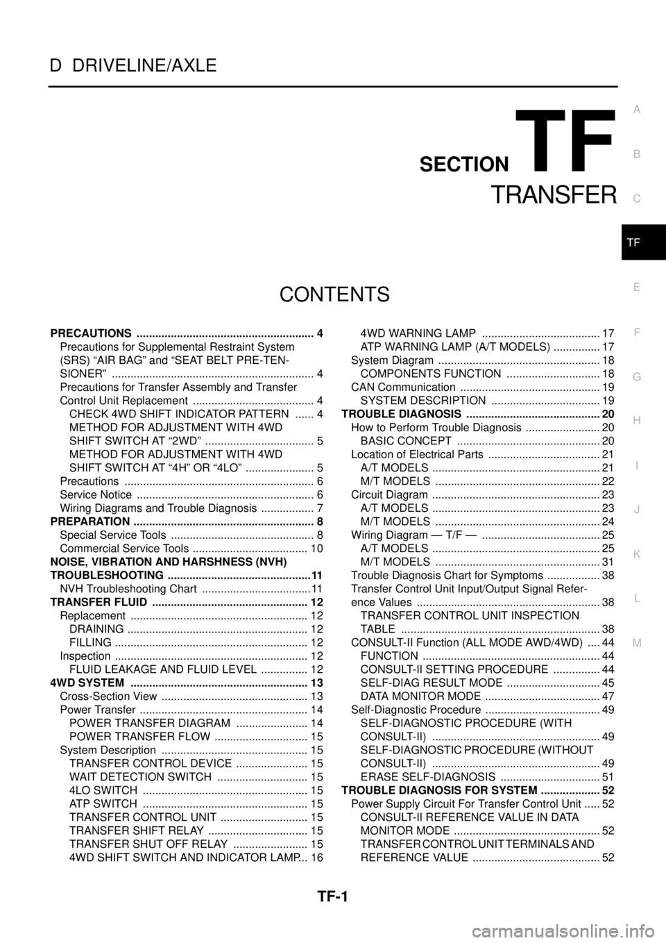
TF-1
TRANSFER
D DRIVELINE/AXLE
CONTENTS
C
E
F
G
H
I
J
K
L
M
SECTIONTF
A
B
TF
TRANSFER
PRECAUTIONS .......................................................... 4
Precautions for Supplemental Restraint System
(SRS)“AIRBAG”and“SEATBELTPRE-TEN-
SIONER” .................................................................. 4
Precautions for Transfer Assembly and Transfer
Control Unit Replacement ........................................ 4
CHECK 4WD SHIFT INDICATOR PATTERN ....... 4
METHOD FOR ADJUSTMENT WITH 4WD
SHIFT SWITCH AT “2WD” .................................... 5
METHOD FOR ADJUSTMENT WITH 4WD
SHIFT SWITCH AT “4H” OR “4LO” ....................... 5
Precautions .............................................................. 6
Service Notice .......................................................... 6
Wiring Diagrams and Trouble Diagnosis .................. 7
PREPARATION ........................................................... 8
Special Service Tools ............................................... 8
Commercial Service Tools ...................................... 10
NOISE, VIBRATION AND HARSHNESS (NVH)
TROUBLESHOOTING ...............................................11
NVH Troubleshooting Chart .................................... 11
TRANSFER FLUID ................................................... 12
Replacement .......................................................... 12
DRAINING ........................................................... 12
FILLING ............................................................... 12
Inspection ............................................................... 12
FLUID LEAKAGE AND FLUID LEVEL ................ 12
4WD SYSTEM .......................................................... 13
Cross-Section View ................................................ 13
Power Transfer ....................................................... 14
POWER TRANSFER DIAGRAM ........................ 14
POWER TRANSFER FLOW ............................... 15
System Description ................................................ 15
TRANSFER CONTROL DEVICE ........................ 15
WAIT DETECTION SWITCH .............................. 15
4LO SWITCH ...................................................... 15
ATP SWITCH ...................................................... 15
TRANSFER CONTROL UNIT ............................. 15
TRANSFER SHIFT RELAY ................................. 15
TRANSFER SHUT OFF RELAY ......................... 15
4WD SHIFT SWITCH AND INDICATOR LAMP... 164WD WARNING LAMP ....................................... 17
ATP WARNING LAMP (A/T MODELS) ................ 17
System Diagram ..................................................... 18
COMPONENTS FUNCTION ............................... 18
CAN Communication .............................................. 19
SYSTEM DESCRIPTION .................................... 19
TROUBLE DIAGNOSIS ............................................ 20
How to Perform Trouble Diagnosis ......................... 20
BASIC CONCEPT ............................................... 20
Location of Electrical Parts ..................................... 21
A/T MODELS ....................................................... 21
M/T MODELS ...................................................... 22
Circuit Diagram ....................................................... 23
A/T MODELS ....................................................... 23
M/T MODELS ...................................................... 24
Wiring Diagram — T/F — ....................................... 25
A/T MODELS ....................................................... 25
M/T MODELS ...................................................... 31
Trouble Diagnosis Chart for Symptoms .................. 38
Transfer Control Unit Input/Output Signal Refer-
ence Values ............................................................ 38
TRANSFER CONTROL UNIT INSPECTION
TABLE ................................................................. 38
CONSULT-II Function (ALL MODE AWD/4WD) ..... 44
FUNCTION .......................................................... 44
CONSULT-II SETTING PROCEDURE ................ 44
SELF-DIAG RESULT MODE ............................... 45
DATA MONITOR MODE ...................................... 47
Self-Diagnostic Procedure ...................................... 49
SELF-DIAGNOSTIC PROCEDURE (WITH
CONSULT-II) ....................................................... 49
SELF-DIAGNOSTIC PROCEDURE (WITHOUT
CONSULT-II) ....................................................... 49
ERASE SELF-DIAGNOSIS ................................. 51
TROUBLE DIAGNOSIS FOR SYSTEM .................... 52
Power Supply Circuit For Transfer Control Unit ...... 52
CONSULT-II REFERENCE VALUE IN DATA
MONITOR MODE ................................................ 52
TRANSFER CONTROL UNIT TERMINALS AND
REFERENCE VALUE .......................................... 52
Page 2971 of 3171
TF-4
PRECAUTIONS
PRECAUTIONS
PFP:00001
Precautions for Supplemental Restraint System (SRS) “AIR BAG” and “SEAT
BELT PRE-TENSIONER”
EDS003ID
The Supplemental Restraint System such as “AIR BAG” and “SEAT BELT PRE-TENSIONER”, used along
with a front seat belt, helps to reduce the risk or severity of injury to the driver and front passenger for certain
types of collision. Information necessary to service the system safely is included in the SRS and SB section of
this Service Manual.
WARNING:
lTo avoid rendering the SRS inoperative, which could increase the risk of personal injury or death
in the event of a collision which would result in air bag inflation, all maintenance must be per-
formed by an authorized NISSAN/INFINITI dealer.
lImproper maintenance, including incorrect removal and installation of the SRS, can lead to per-
sonal injury caused by unintentional activation of the system. For removal of Spiral Cable and Air
Bag Module, see the SRS section.
lDo not use electrical test equipment on any circuit related to the SRS unless instructed to in this
Service Manual. SRS wiring harnesses can be identified by yellow and/or orange harnesses or
harness connectors.
Precautions for Transfer Assembly and Transfer Control Unit ReplacementEDS0031A
lWhen replacing transfer assembly or transfer control unit, check the 4WD shift indicator pattern and
adjustment of the position between transfer assembly and transfer control unit if necessary.
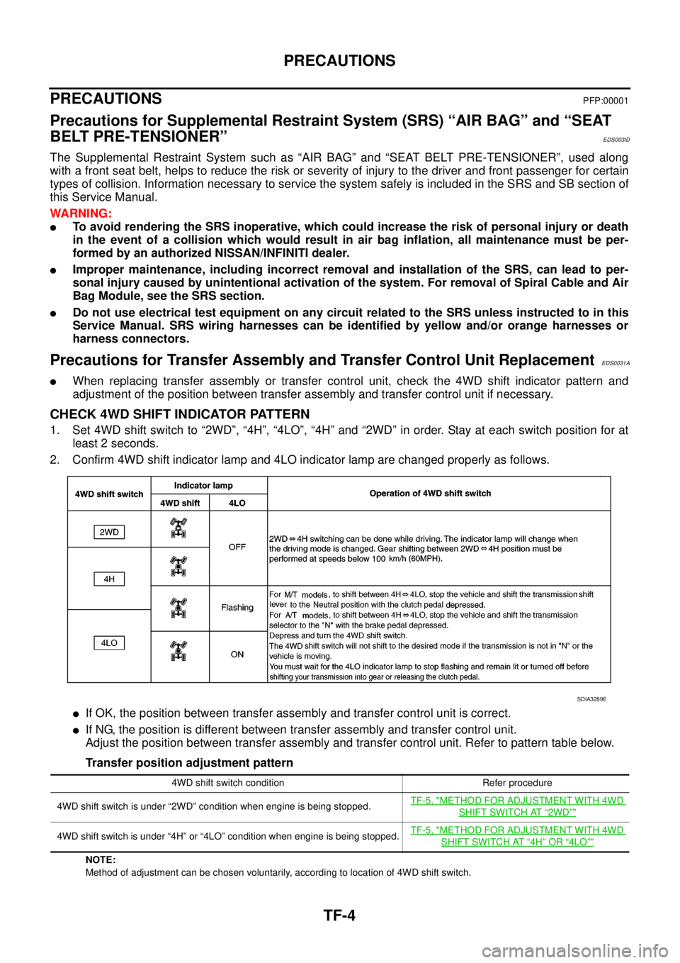
CHECK 4WD SHIFT INDICATOR PATTERN
1. Set 4WD shift switch to “2WD”, “4H”, “4LO”, “4H” and “2WD” in order. Stay at each switch position for at
least 2 seconds.
2. Confirm 4WD shift indicator lamp and 4LO indicator lamp are changed properly as follows.
lIf OK, the position between transfer assembly and transfer control unit is correct.
lIf NG, the position is different between transfer assembly and transfer control unit.
Adjust the position between transfer assembly and transfer control unit. Refer to pattern table below.
Transfer position adjustment pattern
NOTE:
Method of adjustment can be chosen voluntarily, according to location of 4WD shift switch.
SDIA3289E
4WD shift switch condition Refer procedure
4WD shift switch is under “2WD” condition when engine is being stopped.TF-5, "
METHOD FOR ADJUSTMENT WITH 4WD
SHIFT SWITCH AT“2WD”"
4WD shift switch is under “4H” or “4LO” condition when engine is being stopped.TF-5, "METHOD FOR ADJUSTMENT WITH 4WD
SHIFT SWITCH AT“4H”OR“4LO”"
Page 2973 of 3171
TF-6
PRECAUTIONS
If 4WD shift indicator lamp and 4LO indicator lamp do not indicate proper pattern, install new transfer con-
trol unit and retry the above check.
PrecautionsEDS0031B
lBefore connecting or disconnecting the transfer control unit harness connector, turn ignition
switch “OFF” and disconnect the battery cables. Battery voltage is applied to transfer control unit
even if ignition switch is turned “OFF”.
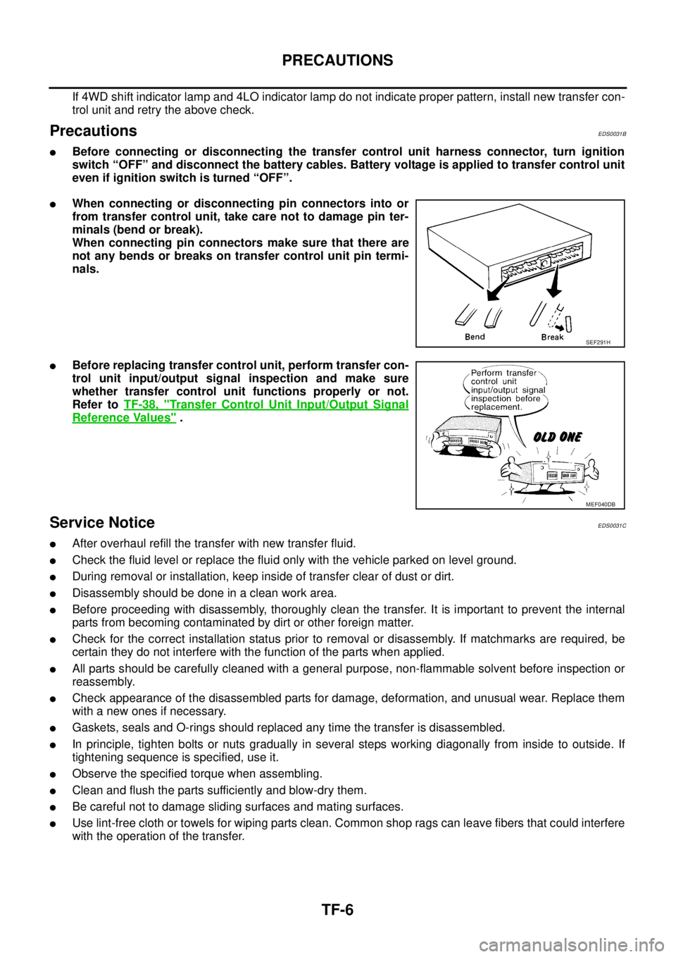
lWhen connecting or disconnecting pin connectors into or
from transfer control unit, take care not to damage pin ter-
minals (bend or break).
When connecting pin connectors make sure that there are
not any bends or breaks on transfer control unit pin termi-
nals.
lBefore replacing transfer control unit, perform transfer con-
trol unit input/output signal inspection and make sure
whether transfer control unit functions properly or not.
Refer toTF-38, "
Transfer Control Unit Input/Output Signal
Reference Values".
Service NoticeEDS0031C
lAfter overhaul refill the transfer with new transfer fluid.
lCheck the fluid level or replace the fluid only with the vehicle parked on level ground.
lDuring removal or installation, keep inside of transfer clear of dust or dirt.
lDisassemblyshouldbedoneinacleanworkarea.
lBefore proceeding with disassembly, thoroughly clean the transfer. It is important to prevent the internal
parts from becoming contaminated by dirt or other foreign matter.
lCheck for the correct installation status prior to removal or disassembly. If matchmarks are required, be
certain they do not interfere with the function of the parts when applied.
lAll parts should be carefully cleaned with a general purpose, non-flammable solvent before inspection or
reassembly.
lCheck appearance of the disassembled parts for damage, deformation, and unusual wear. Replace them
with a new ones if necessary.
lGaskets, seals and O-rings should replaced any time the transfer is disassembled.
lIn principle, tighten bolts or nuts gradually in several steps working diagonally from inside to outside. If
tightening sequence is specified, use it.
lObserve the specified torque when assembling.
lClean and flush the parts sufficiently and blow-dry them.
lBe careful not to damage sliding surfaces and mating surfaces.
lUse lint-free cloth or towels for wiping parts clean. Common shop rags can leave fibers that could interfere
with the operation of the transfer.
SEF291H
MEF040DB
Page 3108 of 3171
WHEEL
WT-3
C
D
F
G
H
I
J
K
L
MA
B
WT
WHEELPFP:40300
InspectionEES002L2
1. Check tires for wear and improper inflation.
2. Check wheels for deformation, cracks and other damage. If
deformed, remove wheel and check wheel runout.
a. Remove tire from wheel and mount wheel on a tire balance
machine.
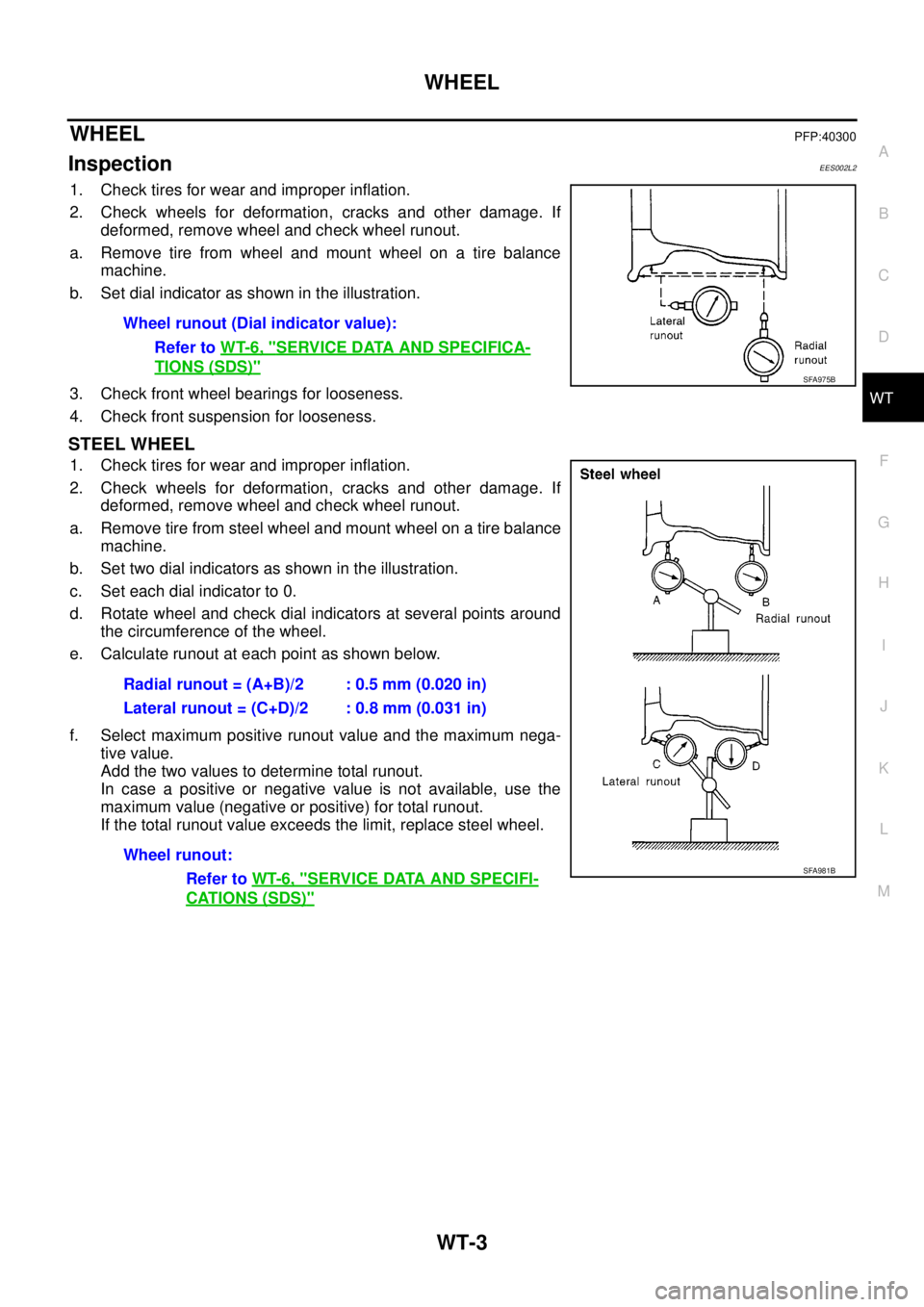
b. Set dial indicator as shown in the illustration.
3. Check front wheel bearings for looseness.
4. Check front suspension for looseness.
STEEL WHEEL
1. Check tires for wear and improper inflation.
2. Check wheels for deformation, cracks and other damage. If
deformed, remove wheel and check wheel runout.
a. Remove tire from steel wheel and mount wheel on a tire balance
machine.
b. Set two dial indicators as shown in the illustration.
c. Set each dial indicator to 0.
d. Rotate wheel and check dial indicators at several points around
the circumference of the wheel.
e. Calculate runout at each point as shown below.
f. Select maximum positive runout value and the maximum nega-
tive value.
Add the two values to determine total runout.
In case a positive or negative value is not available, use the
maximum value (negative or positive) for total runout.
If the total runout value exceeds the limit, replace steel wheel.Wheel runout (Dial indicator value):
Refer toWT-6, "
SERVICE DATA AND SPECIFICA-
TIONS (SDS)"SFA975B
Radial runout = (A+B)/2 : 0.5 mm (0.020 in)
Lateral runout = (C+D)/2 : 0.8 mm (0.031 in)
Wheel runout:
Refer toWT-6, "
SERVICE DATA AND SPECIFI-
CATIONS (SDS)"
SFA981B