Page 2413 of 3171

MTC-26
AIR CONDITIONER CONTROL
AIR CONDITIONER CONTROL
PFP:27500
DescriptionEJS005FW
The front air control provides regulation of the vehicle's interior temperature. The system is based on the posi-
tion of the front air controls temperature switch selected by the driver. This is done by utilizing a microcom-
puter, also referred to as the front air control, which receives input signals from the following three sensors:
lIntake sensor
lPBR (Position Balanced Resistor).
The front air control uses these signals (including the set position of the temperature switch) to control:
lOutlet air volume
lAir temperature
lAir distribution
The front air control is used to select:
lOutlet air volume
lAir temperature/distribution
OperationEJS005FX
AIR MIX DOOR CONTROL
The air mix door is controlled so that in-vehicle temperature changed based on the position of the temperature
switch.
BLOWER SPEED CONTROL
Blower speed is controlled based on front blower switch settings.
When blower switch is turned, the blower motor starts and increases air flow volume each time the blower
switch is turned counterclockwise, and decreases air flow volume each time the blower switch is turned coun-
terclockwise.
When engine coolant temperature is low, the blower motor operation is delayed to prevent cool air from flow-
ing.
INTAKE DOORS CONTROL
The intake doors are controlled by the recirculation switch setting, and the mode (defroster) switch setting.
MODE DOOR CONTROL
The mode door is controlled by the position of the mode switch.
DEFROSTER DOOR CONTROL
The defroster door is controlled by: Turning the defroster dial to front defroster.
Page 2436 of 3171

TROUBLE DIAGNOSIS
MTC-49
C
D
E
F
G
H
I
K
L
MA
B
MTC
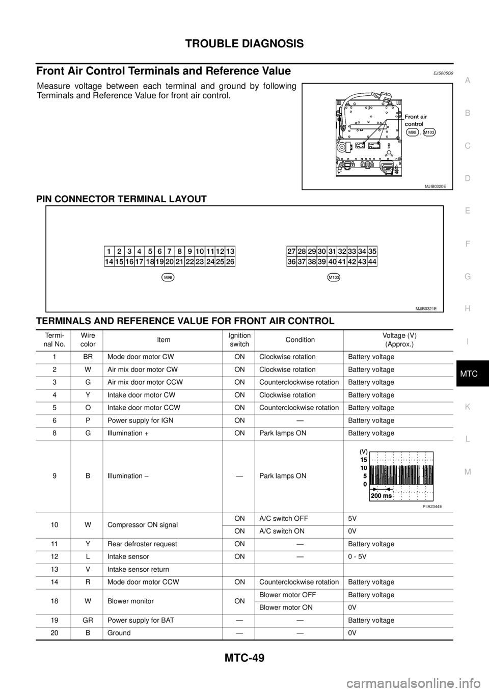
Front Air Control Terminals and Reference ValueEJS005G9
Measure voltage between each terminal and ground by following
Terminals and Reference Value for front air control.
PIN CONNECTOR TERMINAL LAYOUT
TERMINALS AND REFERENCE VALUE FOR FRONT AIR CONTROL
MJIB0320E
MJIB0321E
Te r m i -
nal No.Wire
colorItemIgnition
switchConditionVoltage (V)
(Approx.)
1 BR Mode door motor CW ON Clockwise rotation Battery voltage
2 W Air mix door motor CW ON Clockwise rotation Battery voltage
3 G Air mix door motor CCW ON Counterclockwise rotation Battery voltage
4 Y Intake door motor CW ON Clockwise rotation Battery voltage
5 O Intake door motor CCW ON Counterclockwise rotation Battery voltage
6 P Power supply for IGN ON — Battery voltage
8 G Illumination + ON Park lamps ON Battery voltage
9 B Illumination – — Park lamps ON
10 W Compressor ON signalON A/C switch OFF 5V
ON A/C switch ON 0V
11 Y Rear defroster request ON — Battery voltage
12 L Intake sensor ON — 0 - 5V
13 V Intake sensor return
14 R Mode door motor CCW ON Counterclockwise rotation Battery voltage
18 W Blower monitor ONBlower motor OFF Battery voltage
Blower motor ON 0V
19 GR Power supply for BAT — — Battery voltage
20 B Ground — — 0V
PIIA2344E
Page 2440 of 3171

TROUBLE DIAGNOSIS
MTC-53
C
D
E
F
G
H
I
K
L
MA
B
MTC
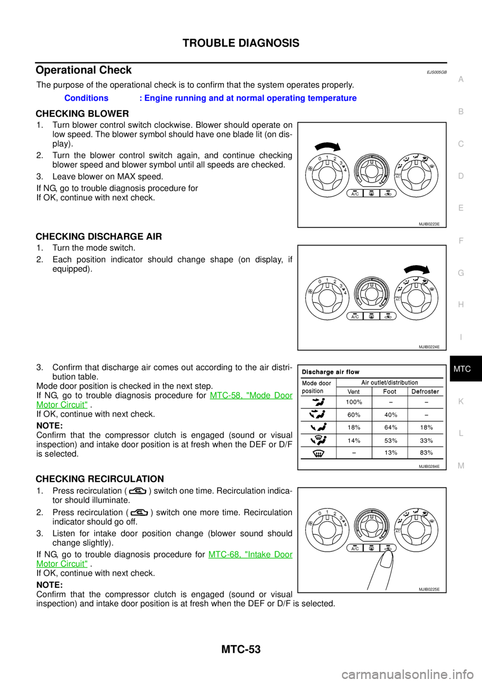
Operational CheckEJS005GB
The purpose of the operational check is to confirm that the system operates properly.
CHECKING BLOWER
1. Turn blower control switch clockwise. Blower should operate on
low speed. The blower symbol should have one blade lit (on dis-
play).
2. Turn the blower control switch again, and continue checking
blower speed and blower symbol until all speeds are checked.
3. Leave blower on MAX speed.
If NG, go to trouble diagnosis procedure for
If OK, continue with next check.
CHECKING DISCHARGE AIR
1. Turn the mode switch.
2. Each position indicator should change shape (on display, if
equipped).
3. Confirm that discharge air comes out according to the air distri-
bution table.
Mode door position is checked in the next step.
If NG, go to trouble diagnosis procedure forMTC-58, "
Mode Door
Motor Circuit".
If OK, continue with next check.
NOTE:
Confirm that the compressor clutch is engaged (sound or visual
inspection) and intake door position is at fresh when the DEF or D/F
is selected.
CHECKING RECIRCULATION
1. Press recirculation ( ) switch one time. Recirculation indica-
tor should illuminate.
2. Press recirculation ( ) switch one more time. Recirculation
indicator should go off.
3. Listen for intake door position change (blower sound should
change slightly).
If NG, go to trouble diagnosis procedure forMTC-68, "
Intake Door
Motor Circuit".
If OK, continue with next check.
NOTE:
Confirm that the compressor clutch is engaged (sound or visual
inspection) and intake door position is at fresh when the DEF or D/F is selected.Conditions : Engine running and at normal operating temperature
MJIB0223E
MJIB0224E
MJIB0284E
MJIB0225E
Page 2441 of 3171

MTC-54
TROUBLE DIAGNOSIS
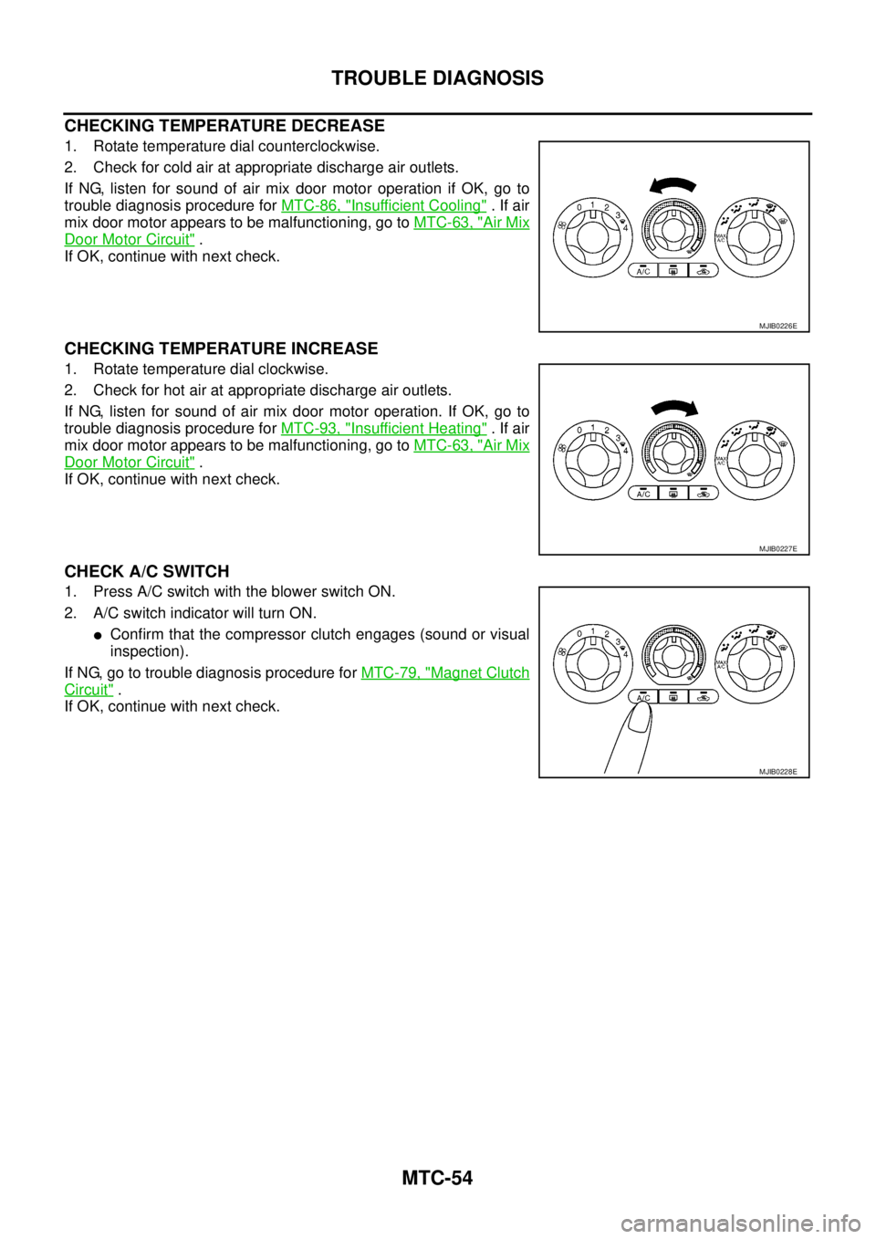
CHECKING TEMPERATURE DECREASE
1. Rotate temperature dial counterclockwise.
2. Check for cold air at appropriate discharge air outlets.
If NG, listen for sound of air mix door motor operation if OK, go to
trouble diagnosis procedure forMTC-86, "
Insufficient Cooling".Ifair
mix door motor appears to be malfunctioning, go toMTC-63, "
Air Mix
Door Motor Circuit".
If OK, continue with next check.
CHECKING TEMPERATURE INCREASE
1. Rotate temperature dial clockwise.
2. Check for hot air at appropriate discharge air outlets.
If NG, listen for sound of air mix door motor operation. If OK, go to
trouble diagnosis procedure forMTC-93, "
Insufficient Heating".Ifair
mix door motor appears to be malfunctioning, go toMTC-63, "
Air Mix
Door Motor Circuit".
If OK, continue with next check.
CHECK A/C SWITCH
1. Press A/C switch with the blower switch ON.
2. A/C switch indicator will turn ON.
lConfirm that the compressor clutch engages (sound or visual
inspection).
If NG, go to trouble diagnosis procedure forMTC-79, "
Magnet Clutch
Circuit".
If OK, continue with next check.
MJIB0226E
MJIB0227E
MJIB0228E
Page 2504 of 3171
DUCTS AND GRILLES
MTC-117
C
D
E
F
G
H
I
K
L
MA
B
MTC
NOTE:
To remove the overhead console front and rear grilles, turn the grille counter-clockwise to release the
grille from the overhead console trim panel.
Installation
Installation is in the reverse order of removal.
Page 2522 of 3171
SERVICE DATA AND SPECIFICATIONS (SDS)
MTC-135
C
D
E
F
G
H
I
K
L
MA
B
MTC
SERVICE DATA AND SPECIFICATIONS (SDS)PFP:00030
Service Data and Specifications (SDS)EJS005HS
COMPRESSOR
LUBRICANT
REFRIGERANT
ENGINE IDLING SPEED
Refer toEC-357, "General Specifications".
BELT TENSION
Refer toEM-13, "Deflection Adjustment".
MakeZEXEL VALEO CLIMATE CONTROL
ModelDKS-17D
Ty p eSwash plate
Displacement
175.5 cm
3(10.7 in3)/rev
Cylinder bore´stroke 30.5 mm (1.20 in) x 24.0 mm (0.94 in)
Direction of rotation Clockwise (viewed from drive end)
Drive belt Poly V
MakeZEXEL VALEO CLIMATE CONTROL
ModelDKS-17D
NameNISSAN A/C System Lubricant Type S (DH-PS)
Part number KLH00-PAGS0
Capacity Total in system
290m (10.2lmpfloz)
Ty p eHFC-134a (R-134a)
Capacity 1080±50g(38.09±1.76 oz)
Page 2650 of 3171
POWER STEERING GEAR AND LINKAGE
PS-23
C
D
E
F
H
I
J
K
L
MA
B
PS
18. Set dial gauge as shown in the figure. Measure vertical move-
ment of rack assembly when pinion is turned clockwise with
torque of 19.6 N·m (2.0 kg-m, 14 ft-lb). Readjust adjusting screw
angle if the measured value is outside the standard. Replace
steering gear assembly if the measured value is still outside the
standard or adjusting screw rotating torque is 5 N·m (0.51 kg-m,
44 in-lb) or less.
19. Install large end of boot to gear housing assembly.
20. Install small end of boot to inner socket boot mounting groove.
21. Install boot clamps to boots, as shown in the figure.
SGIA1147E
Measuring pointRack axial direction 5 mm (0.20 in) from housing end surface
Rack radial direction Axial direction of the adjusting screw
Vertical movement 0.265 mm (0.0104 in)
SGIA1325E
AST139
Page 2681 of 3171

RF-4
SQUEAK AND RATTLE TROUBLE DIAGNOSES
SQUEAK AND RATTLE TROUBLE DIAGNOSES
PFP:00000
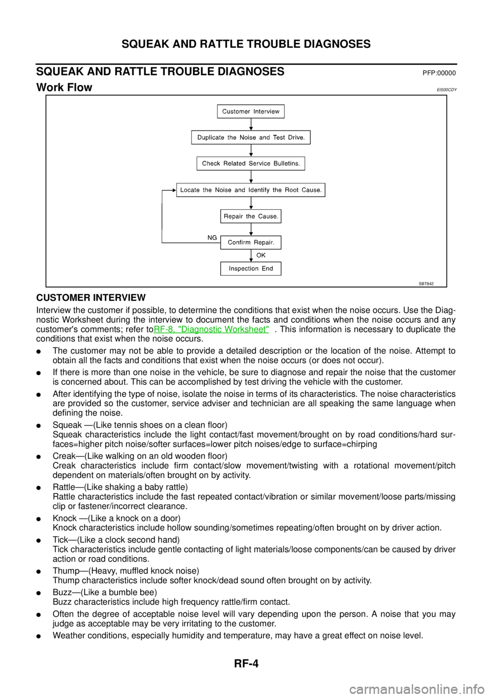
Work FlowEIS00CDY
CUSTOMER INTERVIEW
Interview the customer if possible, to determine the conditions that exist when the noise occurs. Use the Diag-
nostic Worksheet during the interview to document the facts and conditions when the noise occurs and any
customer's comments; refer toRF-8, "
Diagnostic Worksheet". This information is necessary to duplicate the
conditions that exist when the noise occurs.
lThe customer may not be able to provide a detailed description or the location of the noise. Attempt to
obtain all the facts and conditions that exist when the noise occurs (or does not occur).
lIf there is more than one noise in the vehicle, be sure to diagnose and repair the noise that the customer
is concerned about. This can be accomplished by test driving the vehicle with the customer.
lAfter identifying the type of noise, isolate the noise in terms of its characteristics. The noise characteristics
are provided so the customer, service adviser and technician are all speaking the same language when
defining the noise.
lSqueak —(Like tennis shoes on a clean floor)
Squeak characteristics include the light contact/fast movement/brought on by road conditions/hard sur-
faces=higher pitch noise/softer surfaces=lower pitch noises/edge to surface=chirping
lCreak—(Like walking on an old wooden floor)
Creak characteristics include firm contact/slow movement/twisting with a rotational movement/pitch
dependent on materials/often brought on by activity.
lRattle—(Like shaking a baby rattle)
Rattle characteristics include the fast repeated contact/vibration or similar movement/loose parts/missing
clip or fastener/incorrect clearance.
lKnock —(Like a knock on a door)
Knock characteristics include hollow sounding/sometimes repeating/often brought on by driver action.
lTick—(Like a clock second hand)
Tick characteristics include gentle contacting of light materials/loose components/can be caused by driver
action or road conditions.
lThump—(Heavy, muffled knock noise)
Thump characteristics include softer knock/dead sound often brought on by activity.
lBuzz—(Like a bumble bee)
Buzz characteristics include high frequency rattle/firm contact.
lOften the degree of acceptable noise level will vary depending upon the person. A noise that you may
judge as acceptable may be very irritating to the customer.
lWeather conditions, especially humidity and temperature, may have a great effect on noise level.
SBT842