2005 NISSAN NAVARA clock
[x] Cancel search: clockPage 1763 of 3171
IP-4
SQUEAK AND RATTLE TROUBLE DIAGNOSES
SQUEAK AND RATTLE TROUBLE DIAGNOSES
PFP:00000
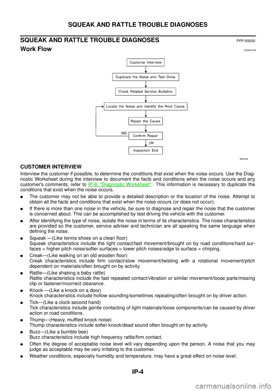
Work FlowEIS00DYW
CUSTOMER INTERVIEW
Interview the customer if possible, to determine the conditions that exist when the noise occurs. Use the Diag-
nostic Worksheet during the interview to document the facts and conditions when the noise occurs and any
customer's comments; refer toIP-8, "
Diagnostic Worksheet". This information is necessary to duplicate the
conditions that exist when the noise occurs.
lThe customer may not be able to provide a detailed description or the location of the noise. Attempt to
obtain all the facts and conditions that exist when the noise occurs (or does not occur).
lIf there is more than one noise in the vehicle, be sure to diagnose and repair the noise that the customer
is concerned about. This can be accomplished by test driving the vehicle with the customer.
lAfter identifying the type of noise, isolate the noise in terms of its characteristics. The noise characteristics
are provided so the customer, service adviser and technician are all speaking the same language when
defining the noise.
lSqueak —(Like tennis shoes on a clean floor)
Squeak characteristics include the light contact/fast movement/brought on by road conditions/hard sur-
faces = higher pitch noise/softer surfaces = lower pitch noises/edge to surface = chirping.
lCreak—(Like walking on an old wooden floor)
Creak characteristics include firm contact/slow movement/twisting with a rotational movement/pitch
dependent on materials/often brought on by activity.
lRattle—(Like shaking a baby rattle)
Rattle characteristics include the fast repeated contact/vibration or similar movement/loose parts/missing
clip or fastener/incorrect clearance.
lKnock —(Like a knock on a door)
Knock characteristics include hollow sounding/sometimes repeating/often brought on by driver action.
lTick—(Like a clock second hand)
Tick characteristics include gentle contacting of light materials/loose components/can be caused by driver
action or road conditions.
lThump—(Heavy, muffled knock noise)
Thump characteristics include softer knock/dead sound often brought on by activity.
lBuzz—(Like a bumble bee)
Buzz characteristics include high frequency rattle/firm contact.
lOften the degree of acceptable noise level will vary depending upon the person. A noise that you may
judge as acceptable may be very irritating to the customer.
lWeather conditions, especially humidity and temperature, may have a great effect on noise level.
SBT842
Page 2112 of 3171
HEADLAMP -CONVENTIONAL TYPE-
LT-29
C
D
E
F
G
H
I
J
L
MA
B
LT
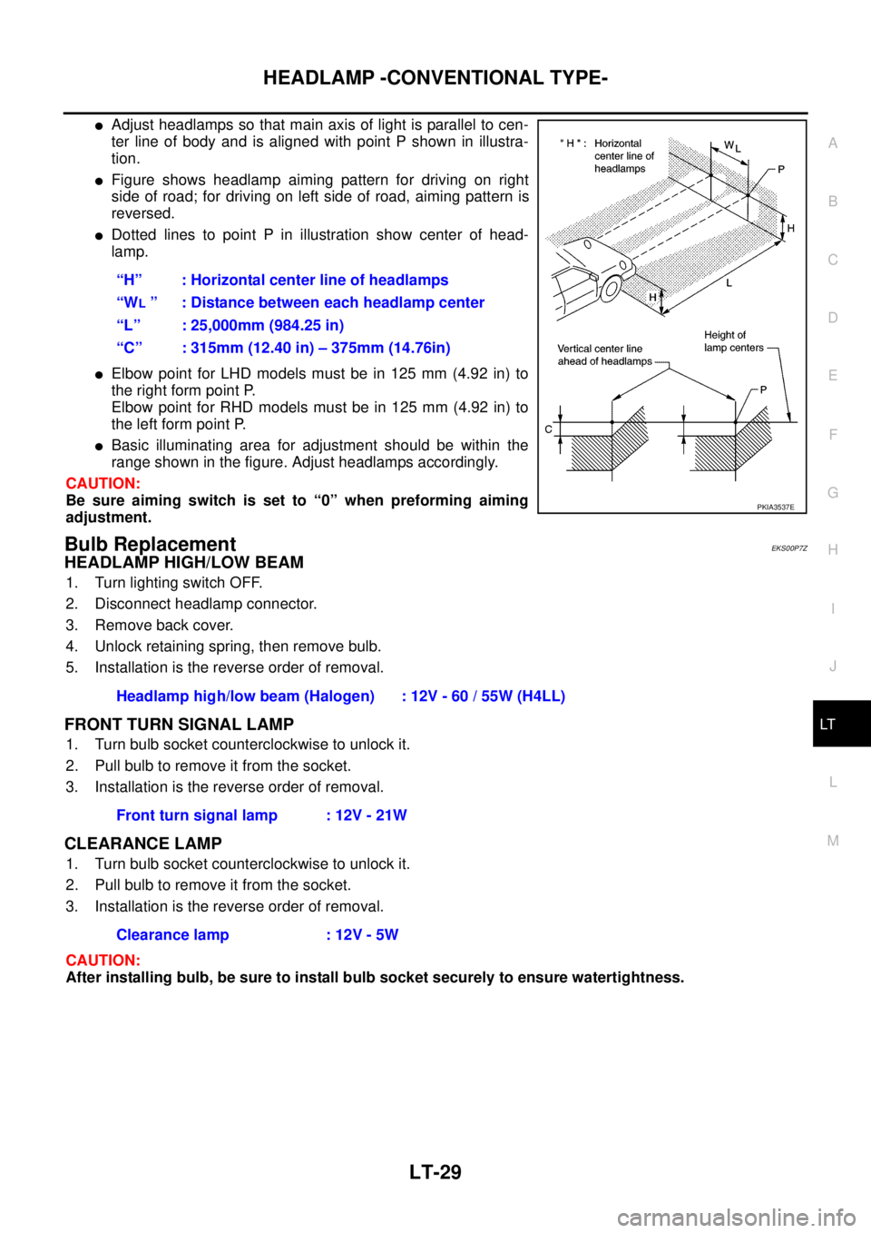
lAdjust headlamps so that main axis of light is parallel to cen-
ter line of body and is aligned with point P shown in illustra-
tion.
lFigure shows headlamp aiming pattern for driving on right
side of road; for driving on left side of road, aiming pattern is
reversed.
lDotted lines to point P in illustration show center of head-
lamp.
lElbow point for LHD models must be in 125 mm (4.92 in) to
the right form point P.
Elbow point for RHD models must be in 125 mm (4.92 in) to
the left form point P.
lBasic illuminating area for adjustment should be within the
range shown in the figure. Adjust headlamps accordingly.
CAUTION:
Be sure aiming switch is set to “0” when preforming aiming
adjustment.
Bulb ReplacementEKS00P7Z
HEADLAMP HIGH/LOW BEAM
1. Turn lighting switch OFF.
2. Disconnect headlamp connector.
3. Remove back cover.
4. Unlock retaining spring, then remove bulb.
5. Installation is the reverse order of removal.
FRONT TURN SIGNAL LAMP
1. Turn bulb socket counterclockwise to unlock it.
2. Pull bulb to remove it from the socket.
3. Installation is the reverse order of removal.
CLEARANCE LAMP
1. Turn bulb socket counterclockwise to unlock it.
2. Pull bulb to remove it from the socket.
3. Installation is the reverse order of removal.
CAUTION:
After installing bulb, be sure to install bulb socket securely to ensure watertightness.“H” : Horizontal center line of headlamps
“W
L” : Distance between each headlamp center
“L” : 25,000mm (984.25 in)
“C” : 315mm (12.40 in) – 375mm (14.76in)
PKIA3537E
Headlamp high/low beam (Halogen) : 12V - 60 / 55W (H4LL)
Front turn signal lamp : 12V - 21W
Clearance lamp : 12V - 5W
Page 2168 of 3171
FRONT FOG LAMP
LT-85
C
D
E
F
G
H
I
J
L
MA
B
LT
Aiming AdjustmentEKS00P4D
The fog lamp is a semi-sealed beam type which uses a replaceable halogen bulb. Before performing aiming
adjustment, make sure of the following.
lKeep all tires inflated to correct pressure.
lPlace vehicle on level surface.
lSee that vehicle is unloaded (except for full levels of coolant, engine oil and fuel, and spare tire, jack, and
tools). Have the driver or equivalent weight placed in driver's seat.
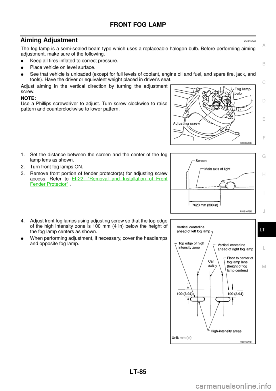
Adjust aiming in the vertical direction by turning the adjustment
screw.
NOTE:
Use a Phillips screwdriver to adjust. Turn screw clockwise to raise
pattern and counterclockwise to lower pattern.
1. Set the distance between the screen and the center of the fog
lamp lens as shown.
2. Turn front fog lamps ON.
3. Remove front portion of fender protector(s) for adjusting screw
access. Refer toEI-22, "
Removal and Installation of Front
Fender Protector".
4. Adjust front fog lamps using adjusting screw so that the top edge
of the high intensity zone is 100 mm (4 in) below the height of
the fog lamp centers as shown.
lWhen performing adjustment, if necessary, cover the headlamps
and opposite fog lamp.
SKIB6539E
PKIB1672E
PKIB1673E
Page 2169 of 3171
LT-86
FRONT FOG LAMP
Bulb Replacement
EKS00P4E
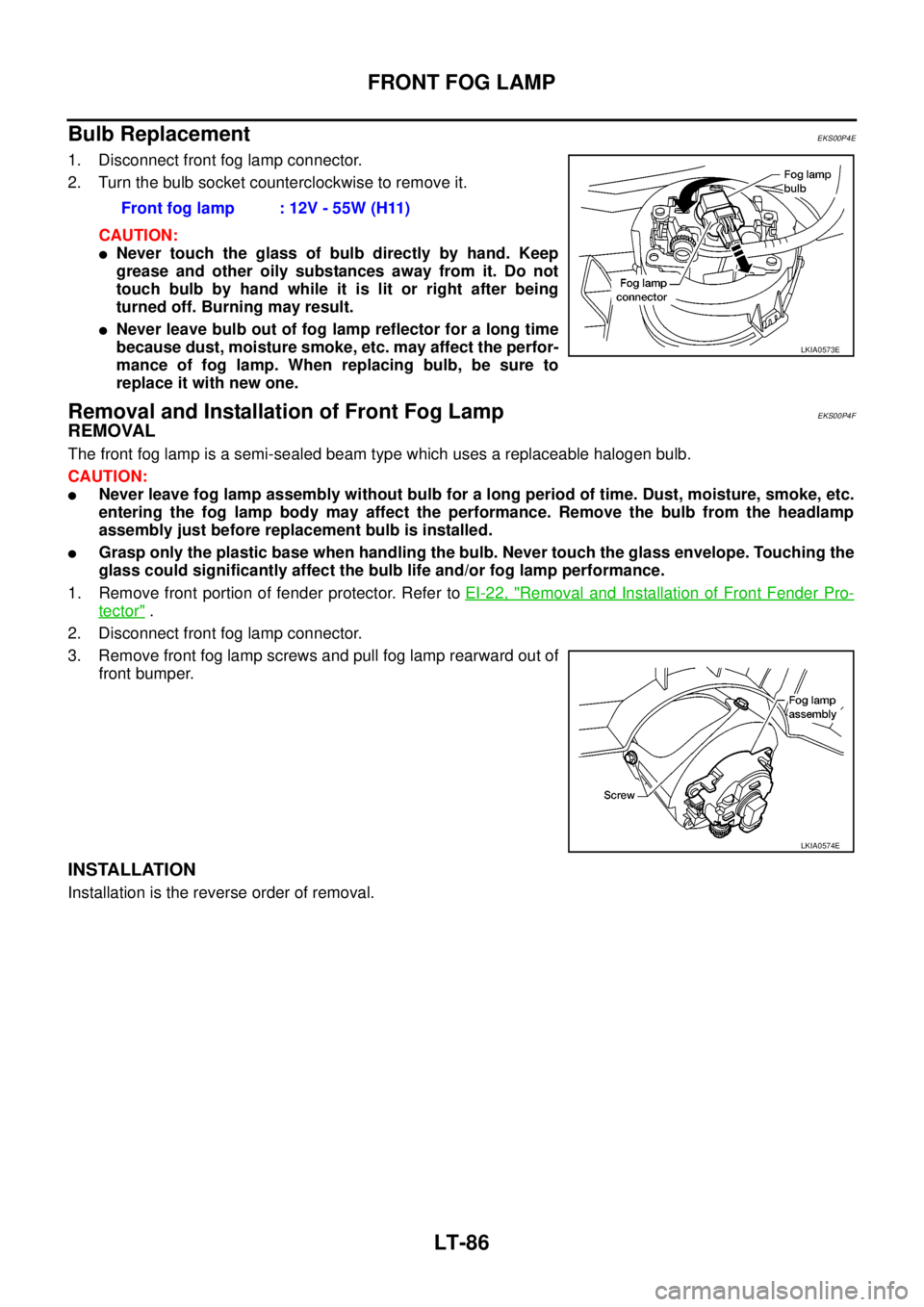
1. Disconnect front fog lamp connector.
2. Turn the bulb socket counterclockwise to remove it.
CAUTION:
lNever touch the glass of bulb directly by hand. Keep
grease and other oily substances away from it. Do not
touch bulb by hand while it is lit or right after being
turned off. Burning may result.
lNever leave bulb out of fog lamp reflector for a long time
because dust, moisture smoke, etc. may affect the perfor-
mance of fog lamp. When replacing bulb, be sure to
replace it with new one.
Removal and Installation of Front Fog LampEKS00P4F
REMOVAL
The front fog lamp is a semi-sealed beam type which uses a replaceable halogen bulb.
CAUTION:
lNever leave fog lamp assembly without bulb for a long period of time. Dust, moisture, smoke, etc.
entering the fog lamp body may affect the performance. Remove the bulb from the headlamp
assembly just before replacement bulb is installed.
lGrasp only the plastic base when handling the bulb. Never touch the glass envelope. Touching the
glass could significantly affect the bulb life and/or fog lamp performance.
1. Remove front portion of fender protector. Refer toEI-22, "
Removal and Installation of Front Fender Pro-
tector".
2. Disconnect front fog lamp connector.
3. Remove front fog lamp screws and pull fog lamp rearward out of
front bumper.
INSTALLATION
Installation is the reverse order of removal.Front fog lamp : 12V - 55W (H11)
LKIA0573E
LKIA0574E
Page 2194 of 3171
TURN SIGNAL AND HAZARD WARNING LAMPS
LT-111
C
D
E
F
G
H
I
J
L
MA
B
LT
Bulb Replacement (Front Turn Signal Lamp)EKS00P8G
Refer toLT-29, "Bulb Replacement".
Bulb Replacement (Rear Turn Signal Lamp)EKS00P8H
Refer toLT- 1 4 3 , "Bulb Replacement".
Bulb Replacement (Side Turn Signal Lamp)EKS00P8I
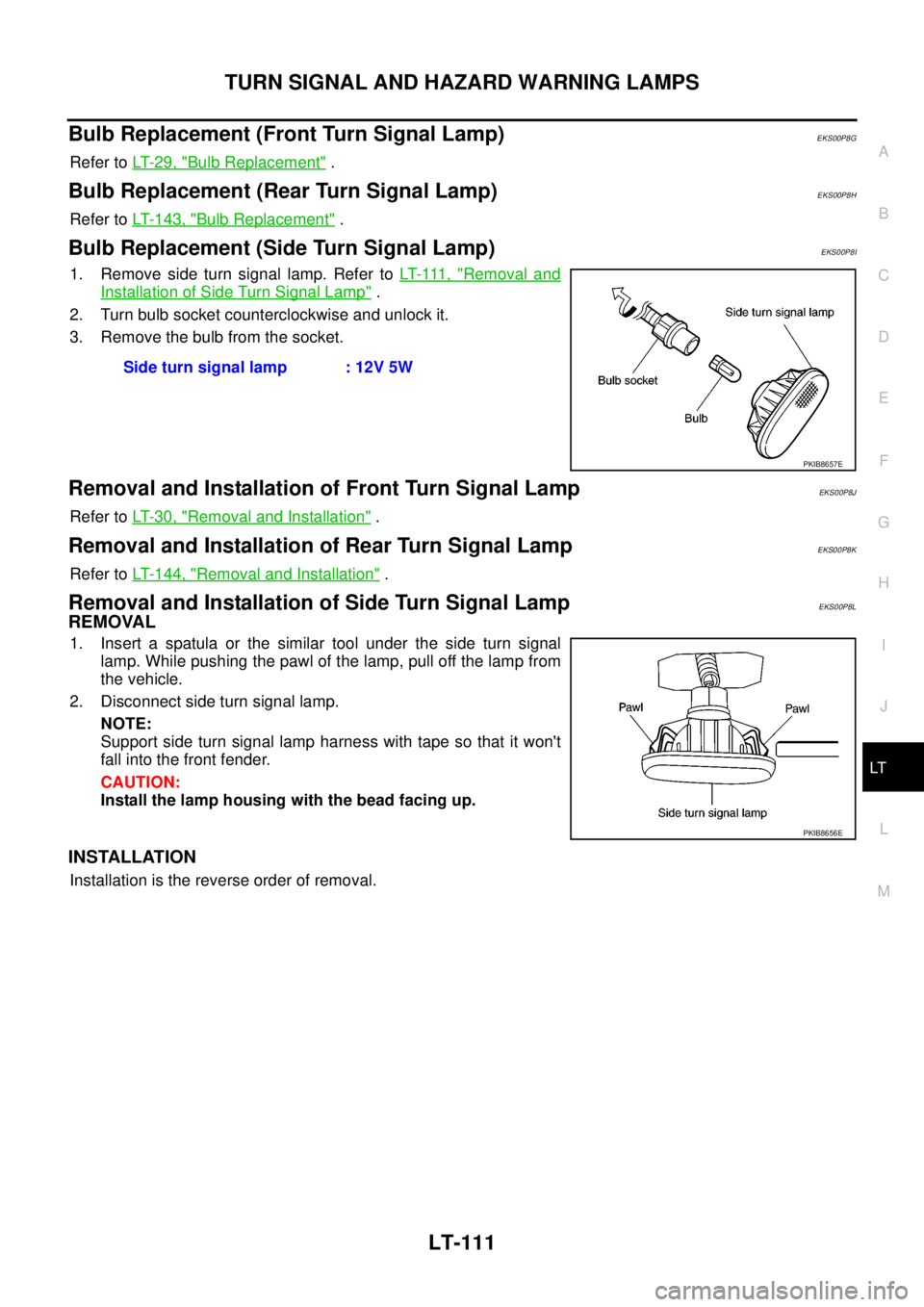
1. Remove side turn signal lamp. Refer toLT- 111 , "Removal and
Installation of Side Turn Signal Lamp".
2. Turn bulb socket counterclockwise and unlock it.
3. Remove the bulb from the socket.
Removal and Installation of Front Turn Signal LampEKS00P8J
Refer toLT-30, "Removal and Installation".
Removal and Installation of Rear Turn Signal LampEKS00P8K
Refer toLT- 1 4 4 , "Removal and Installation".
Removal and Installation of Side Turn Signal LampEKS00P8L
REMOVAL
1. Insert a spatula or the similar tool under the side turn signal
lamp. While pushing the pawl of the lamp, pull off the lamp from
the vehicle.
2. Disconnect side turn signal lamp.
NOTE:
Support side turn signal lamp harness with tape so that it won't
fall into the front fender.
CAUTION:
Install the lamp housing with the bead facing up.
INSTALLATION
Installation is the reverse order of removal.Side turn signal lamp : 12V 5W
PKIB8657E
PKIB8656E
Page 2226 of 3171
REAR COMBINATION LAMP
LT-143
C
D
E
F
G
H
I
J
L
MA
B
LT
REAR COMBINATION LAMPPFP:26554
Bulb ReplacementEKS00P90
REMOVAL
1. Remove rear combination lamp. Refer toLT- 1 4 4 , "Removal and Installation".
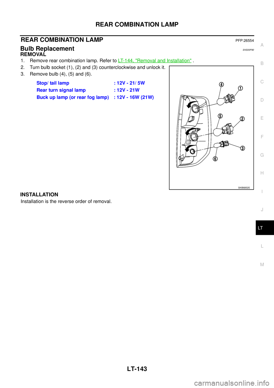
2. Turn bulb socket (1), (2) and (3) counterclockwise and unlock it.
3. Remove bulb (4), (5) and (6).
INSTALLATION
Installation is the reverse order of removal.Stop/taillamp :12V-21/5W
Rear turn signal lamp : 12V - 21W
Buck up lamp (or rear fog lamp) : 12V - 16W (21W)
SKIB6852E
Page 2280 of 3171
DESCRIPTION
MA-5
C
D
E
F
G
H
I
J
K
MA
B
MA
DESCRIPTIONPFP:00000
Pre-Delivery Inspection ItemsELS001K2
Shown below are Pre-delivery Inspection Items required for the new vehicle. It is recommended that
necessary items other than those listed here be added, paying due regard to the conditions in each
country.
Perform applicable items on each model. Consult text of this section for specifications.
Install vehicle protection kit
Fit all accessories ordered (if applicable) (e.g. towbar, audio, navigation, air conditioner, styling kit)
UNDER HOOD — engine off
Check coolant level and cooling system for leaks
Charge battery and check terminals for condition
Check drive belts tension
Check fuel filter for water or dust (diesel only) and fuel system for leaks
Check engine oil level and for oil leaks
Check brake and clutch fluid levels and fluid lines for leaks
Check and top up washer reservoirs
Check power steering fluid level and fluid lines for leaks (if applicable)
Check air conditioning system for gas leaks (if applicable)
ON INSIDE AND OUTSIDE
Install transit fuse if removed for vehicle storage
Check instruments, gauges, lamps, horn and accessories for operation
Check wipers and washers for operation and adjustment
Check interior and door mirrors and sun visors for operation
Set radio code and set clock
Check parking brake adjustment
Check clutch pedal adjustment
Check steering lock operation
Check seat adjusters and seat belts for operation
Check all windows for operation and alignment
Check mouldings, trim and fittings for fit and alignment
Check weatherstrips for fit and adhesion
Check hood, trunk lid, door panels and fuel lid for fit and alignment
Check latches, keys, remote key, door locks and remote trunk lid and fuel lid release for operation
Check wheel nut torques
Check tyre pressure (incl. spare tyre)
Check tool kit and jack for operation
Check automatic transmission/transaxle starter inhibitor (if applicable)
Check sunroof for operation and alignment (if applicable)
UNDER BODY
Check manual transmission/transaxle, differential and transfer box for oil level and oil leaks
Tighten bolts and nuts steering linkage and gear box, axle/suspension parts, propeller and exhaust system
Check brake and clutch lines, and oil/fluid reservoirs for leaks
Remove front suspension spacer blocks (if applicable)
Check body mounting torque (if applicable)
Page 2401 of 3171
MTC-14
PRECAUTIONS
SERVICE COUPLERS
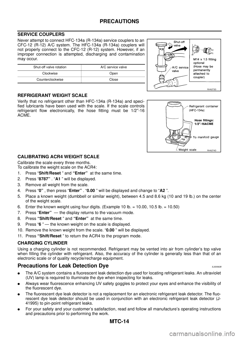
Never attempt to connect HFC-134a (R-134a) service couplers to an
CFC-12 (R-12) A/C system. The HFC-134a (R-134a) couplers will
not properly connect to the CFC-12 (R-12) system. However, if an
improper connection is attempted, discharging and contamination
may occur.
REFRIGERANT WEIGHT SCALE
Verify that no refrigerant other than HFC-134a (R-134a) and speci-
fied lubricants have been used with the scale. If the scale controls
refrigerant flow electronically, the hose fitting must be 1/2²-16
ACME.
CALIBRATING ACR4 WEIGHT SCALE
Calibrate the scale every three months.
To calibrate the weight scale on the ACR4:
1. Press “Shift/Reset”and“Enter”at the same time.
2. Press “8787”.“A1” will be displayed.
3. Remove all weight from the scale.
4. Press “0”, then press “Enter”.“0.00” will be displayed and change to “A2”.
5. Place a known weight (dumbbell or similar weight), between 4.5 and 8.6 kg (10 and 19 lb.) on the center
of the weight scale.
6. Enter the known weight using four digits. (Example 10 lb. = 10.00, 10.5 lb. = 10.50)
7. Press “Enter”— the display returns to the vacuum mode.
8. Press“Shift/Reset”and“Enter”at the same time.
9. Press “6” — the known weight on the scale is displayed.
10. Remove the known weight from the scale. “0.00” will be displayed.
11. Press“Shift/Reset” to return the ACR4 to the program mode.
CHARGING CYLINDER
Using a charging cylinder is not recommended. Refrigerant may be vented into air from cylinder’s top valve
when filling the cylinder with refrigerant. Also, the accuracy of the cylinder is generally less than that of an
electronic scale or of quality recycle/recharge equipment.
Precautions for Leak Detection DyeEJS0062B
lThe A/C system contains a fluorescent leak detection dye used for locating refrigerant leaks. An ultraviolet
(UV) lamp is required to illuminate the dye when inspecting for leaks.
lAlways wear fluorescence enhancing UV safety goggles to protect your eyes and enhance the visibility of
the fluorescent dye.
lThe fluorescent dye leak detector is not a replacement for an electronic refrigerant leak detector. The fluo-
rescent dye leak detector should be used in conjunction with an electronic refrigerant leak detector (J-
41995) to pin-point refrigerant leaks.
lFor your safety and your customer’s satisfaction, read and follow all manufacture’s operating instructions
and precautions prior to performing the work.
Shut-off valve rotation A/C service valve
Clockwise Open
Counterclockwise Close
RHA273D
RHA274D