2005 NISSAN NAVARA clock
[x] Cancel search: clockPage 1009 of 3171
ON BOARD DIAGNOSTIC (OBD) SYSTEM
EC-29
C
D
E
F
G
H
I
J
K
L
MA
EC
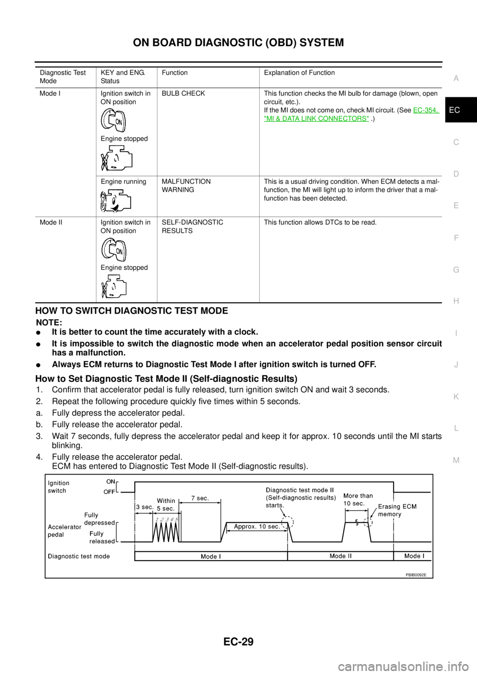
HOWTOSWITCHDIAGNOSTICTESTMODE
NOTE:
lIt is better to count the time accurately with a clock.
lIt is impossible to switch the diagnostic mode when an accelerator pedal position sensor circuit
has a malfunction.
lAlways ECM returns to Diagnostic Test Mode I after ignition switch is turned OFF.
How to Set Diagnostic Test Mode II (Self-diagnostic Results)
1. Confirm that accelerator pedal is fully released, turn ignition switch ON and wait 3 seconds.
2. Repeat the following procedure quickly five times within 5 seconds.
a. Fully depress the accelerator pedal.
b. Fully release the accelerator pedal.
3. Wait 7 seconds, fully depress the accelerator pedal and keep it for approx. 10 seconds until the MI starts
blinking.
4. Fully release the accelerator pedal.
ECM has entered to Diagnostic Test Mode II (Self-diagnostic results).
Diagnostic Test
ModeKEY and ENG.
Statu sFunction Explanation of Function
Mode I Ignition switch in
ON position
Engine stoppedBULB CHECK This function checks the MI bulb for damage (blown, open
circuit, etc.).
If the MI does not come on, check MI circuit. (SeeEC-354,
"MI&DATA LINK CONNECTORS".)
Engine running MALFUNCTION
WARNINGThis is a usual driving condition. When ECM detects a mal-
function, the MI will light up to inform the driver that a mal-
function has been detected.
Mode II Ignition switch in
ON position
Engine stoppedSELF-DIAGNOSTIC
RESULTSThis function allows DTCs to be read.
PBIB0092E
Page 1344 of 3171
EI-6
SQUEAK AND RATTLE TROUBLE DIAGNOSES
SQUEAK AND RATTLE TROUBLE DIAGNOSES
PFP:00000
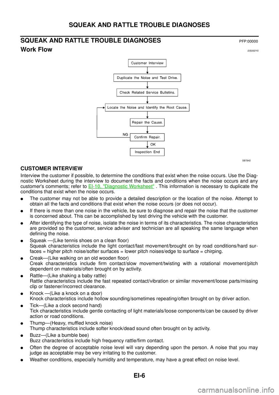
Work FlowEIS00DY5
CUSTOMER INTERVIEW
Interview the customer if possible, to determine the conditions that exist when the noise occurs. Use the Diag-
nostic Worksheet during the interview to document the facts and conditions when the noise occurs and any
customer's comments; refer toEI-10, "
Diagnostic Worksheet". This information is necessary to duplicate the
conditions that exist when the noise occurs.
lThe customer may not be able to provide a detailed description or the location of the noise. Attempt to
obtain all the facts and conditions that exist when the noise occurs (or does not occur).
lIf there is more than one noise in the vehicle, be sure to diagnose and repair the noise that the customer
is concerned about. This can be accomplished by test driving the vehicle with the customer.
lAfter identifying the type of noise, isolate the noise in terms of its characteristics. The noise characteristics
are provided so the customer, service adviser and technician are all speaking the same language when
defining the noise.
lSqueak —(Like tennis shoes on a clean floor)
Squeak characteristics include the light contact/fast movement/brought on by road conditions/hard sur-
faces = higher pitch noise/softer surfaces = lower pitch noises/edge to surface = chirping.
lCreak—(Like walking on an old wooden floor)
Creak characteristics include firm contact/slow movement/twisting with a rotational movement/pitch
dependent on materials/often brought on by activity.
lRattle—(Like shaking a baby rattle)
Rattle characteristics include the fast repeated contact/vibration or similar movement/loose parts/missing
clip or fastener/incorrect clearance.
lKnock —(Like a knock on a door)
Knock characteristics include hollow sounding/sometimes repeating/often brought on by driver action.
lTick—(Like a clock second hand)
Tick characteristics include gentle contacting of light materials/loose components/can be caused by driver
action or road conditions.
lThump—(Heavy, muffled knock noise)
Thump characteristics include softer knock/dead sound often brought on by activity.
lBuzz—(Like a bumble bee)
Buzz characteristics include high frequency rattle/firm contact.
lOften the degree of acceptable noise level will vary depending upon the person. A noise that you may
judge as acceptable may be very irritating to the customer.
lWeather conditions, especially humidity and temperature, may have a great effect on noise level.
SBT842
Page 1448 of 3171
EM-66
CAMSHAFT
Valve Clearance
EBS01E67
INSPECTION
lWhen the camshaft or parts in connection with valves are removed or replaced, and a malfunction has
occurred (poor starting, idling, or other malfunction) due to the misadjustment of the valve clearance,
inspect as follows.
lInspect and adjust when the engine is cool (at normal temperature).
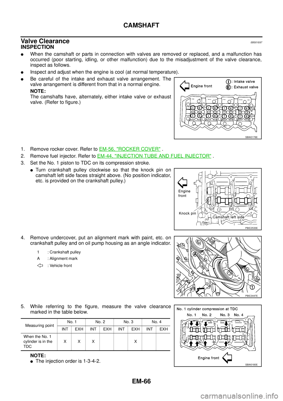
lBe careful of the intake and exhaust valve arrangement. The
valve arrangement is different from that in a normal engine.
NOTE:
The camshafts have, alternately, either intake valve or exhaust
valve. (Refer to figure.)
1. Remove rocker cover. Refer toEM-56, "
ROCKER COVER".
2. Remove fuel injector. Refer toEM-44, "
INJECTION TUBE AND FUEL INJECTOR".
3. Set the No. 1 piston to TDC on its compression stroke.
lTurn crankshaft pulley clockwise so that the knock pin on
camshaft left side faces straight above. (No position indicator,
etc. is provided on the crankshaft pulley.)
4. Remove undercover, put an alignment mark with paint, etc. on
crankshaft pulley and on oil pump housing as an angle indicator.
5. While referring to the figure, measure the valve clearance
marked in the table below.
NOTE:
lThe injection order is 1-3-4-2.
SBIA0178E
PBIC2533E
1 : Crankshaft pulley
A : Alignment mark
: Vehicle front
PBIC3447E
Measuring pointNo. 1 No. 2 No. 3 No. 4
INT EXH INT EXH INT EXH INT EXH
When the No. 1
cylinder is in the
TDCXXX X
SBIA0180E
Page 1449 of 3171
CAMSHAFT
EM-67
C
D
E
F
G
H
I
J
K
L
MA
EM
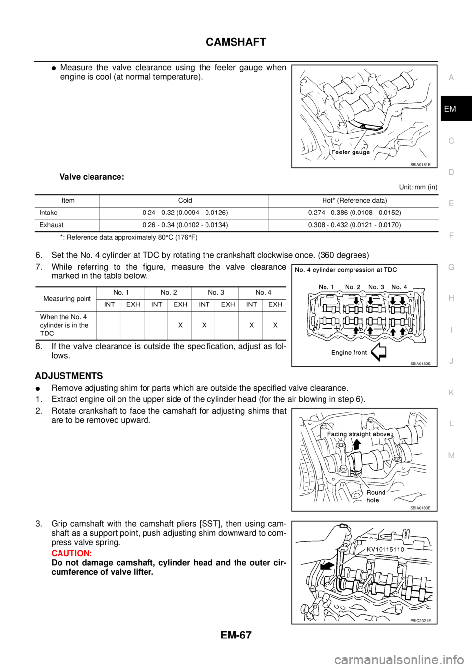
lMeasure the valve clearance using the feeler gauge when
engine is cool (at normal temperature).
Valve clearance:
Unit: mm (in)
*: Reference data approximately 80°C(176°F)
6. Set the No. 4 cylinder at TDC by rotating the crankshaft clockwise once. (360 degrees)
7. While referring to the figure, measure the valve clearance
marked in the table below.
8. If the valve clearance is outside the specification, adjust as fol-
lows.
ADJUSTMENTS
lRemove adjusting shim for parts which are outside the specified valve clearance.
1. Extract engine oil on the upper side of the cylinder head (for the air blowing in step 6).
2. Rotate crankshaft to face the camshaft for adjusting shims that
are to be removed upward.
3. Grip camshaft with the camshaft pliers [SST], then using cam-
shaft as a support point, push adjusting shim downward to com-
press valve spring.
CAUTION:
Do not damage camshaft, cylinder head and the outer cir-
cumference of valve lifter.
SBIA0181E
Item Cold Hot* (Reference data)
Intake 0.24 - 0.32 (0.0094 - 0.0126) 0.274 - 0.386 (0.0108 - 0.0152)
Exhaust 0.26 - 0.34 (0.0102 - 0.0134) 0.308 - 0.432 (0.0121 - 0.0170)
Measuring pointNo. 1 No. 2 No. 3 No. 4
INT EXH INT EXH INT EXH INT EXH
When the No. 4
cylinder is in the
TDCXX XX
SBIA0182E
SBIA0183E
PBIC2321E
Page 1456 of 3171
EM-74
SECONDARY TIMING CHAIN
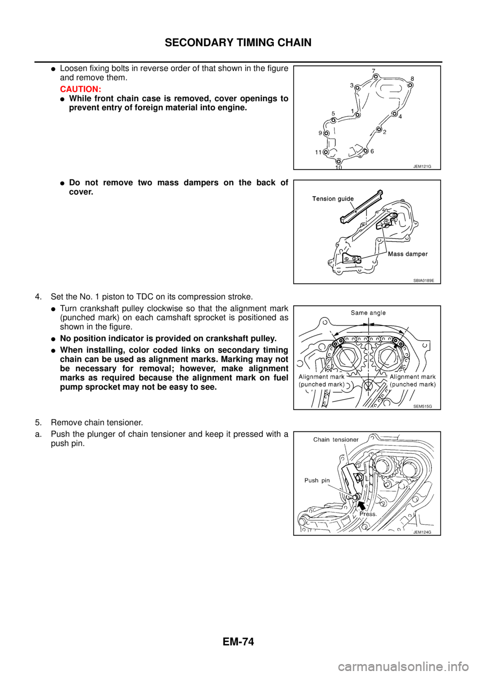
lLoosen fixing bolts in reverse order of that shown in the figure
and remove them.
CAUTION:
lWhile front chain case is removed, cover openings to
prevent entry of foreign material into engine.
lDo not remove two mass dampers on the back of
cover.
4. Set the No. 1 piston to TDC on its compression stroke.
lTurn crankshaft pulley clockwise so that the alignment mark
(punched mark) on each camshaft sprocket is positioned as
showninthefigure.
lNo position indicator is provided on crankshaft pulley.
lWhen installing, color coded links on secondary timing
chain can be used as alignment marks. Marking may not
be necessary for removal; however, make alignment
marks as required because the alignment mark on fuel
pump sprocket may not be easy to see.
5. Remove chain tensioner.
a. Push the plunger of chain tensioner and keep it pressed with a
push pin.
JEM121G
SBIA0189E
SEM515G
JEM124G
Page 1463 of 3171
![NISSAN NAVARA 2005 Repair Workshop Manual PRIMARY TIMING CHAIN
EM-81
C
D
E
F
G
H
I
J
K
L
MA
EM
c. Using the pulley puller [SST], remove crankshaft pulley.
lUse two M6 bolts with approx. 60 mm (2.36 in) shank length
for securing crankshaft pul NISSAN NAVARA 2005 Repair Workshop Manual PRIMARY TIMING CHAIN
EM-81
C
D
E
F
G
H
I
J
K
L
MA
EM
c. Using the pulley puller [SST], remove crankshaft pulley.
lUse two M6 bolts with approx. 60 mm (2.36 in) shank length
for securing crankshaft pul](/manual-img/5/57362/w960_57362-1462.png)
PRIMARY TIMING CHAIN
EM-81
C
D
E
F
G
H
I
J
K
L
MA
EM
c. Using the pulley puller [SST], remove crankshaft pulley.
lUse two M6 bolts with approx. 60 mm (2.36 in) shank length
for securing crankshaft pulley.
9. Remove oil pump housing.
lLoosen bolts in reverse order of that shown in the figure and
remove them.
lU s e t h e s e a l c u t t e r [ S S T: K V 1 0 1111 0 0 ] e t c . f o r r e m o v a l .
10. Remove crankshaft gear.
lRemove crankshaft gear (1) with the following procedure
(4WD models).
a. Make sure that No.1 piston is TDC on its compression stroke.
b. Turn the idler sub gear (3) counterclockwise with snap ring plier
(B) or suitable tool for aligning idler sub gear (3) and idler main
gear (2).
lIf idler gear rotates, hold the flat faces on balancer drive shaft
front end (4).
c. Install internal mechanism securing bolt and plate (Service part:
13012 EB30A and 13013 EB30A) (A) and tighten to the speci-
fied torque.
CAUTION:
lDo not loosen idler gear mounting bolt (5).
lOnly use the genuine internal mechanism securing bolt
and plate (A), or the idler gear (2) and (3) will be damaged.
lDo not remove internal mechanism securing bolt and
plate (A) from idler gear (2) and (3) until crankshaft gear
(1) and all of the parts in connection have been installed.
lIf internal mechanism securing bolt and plate (A) is not
installed, internal mechanism of idler gear (2) and (3) will
disengage after crankshaft gear (1) is removed. This will prohibit the balancer unit from being
reusable.
d. Apply mating marks (C) to crankshaft gear (1) and idler sub gear (3).
e. Remove crankshaft gear (1).
11. Remove front oil seal from oil pump housing.
lPunch out the seal off from the back surface of the oil pump housing using a flat-bladed screwdriver.
CAUTION:
Be careful not to damage oil pump housing.
JEM132G
PBIC3470E
: 4.0 N·m (0.41 kg-m, 35 in-lb)
PBIC3471E
Page 1468 of 3171
EM-86
PRIMARY TIMING CHAIN
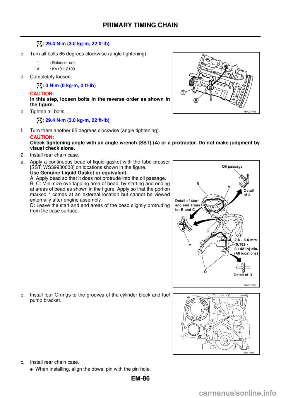
c. Turn all bolts 65 degrees clockwise (angle tightening).
d. Completely loosen.
CAUTION:
In this step, loosen bolts in the reverse order as shown in
the figure.
e. Tighten all bolts.
f. Turn them another 65 degrees clockwise (angle tightening).
CAUTION:
Check tightening angle with an angle wrench [SST] (A) or a protractor. Do not make judgment by
visual check alone.
2. Install rear chain case.
a. Apply a continuous bead of liquid gasket with the tube presser
[SST: WS39930000] on locations shown in the figure.
Use Genuine Liquid Gasket or equivalent.
A: Apply bead so that it does not protrude into the oil passage.
B, C: Minimize overlapping area of bead, by starting and ending
at areas of bead as shown in the figure. Apply so that the portion
marked * comes at an external location but cannot be viewed
externally after engine assembly.
D: Leave the start and end areas of the bead slightly protruding
from the case surface.
b. Install four O-rings to the grooves of the cylinder block and fuel
pump bracket.
c. Install rear chain case.
lWhen installing, align the dowel pin with the pin hole.: 29.4 N·m (3.0 kg-m, 22 ft-lb)
1 : Balancer unit
A : KV10112100
: 0 N·m (0 kg-m, 0 ft-lb)
: 29.4 N·m (3.0 kg-m, 22 ft-lb)
PBIC3474E
PBIC1255E
JEM141G
Page 1691 of 3171
SQUEAK AND RATTLE TROUBLE DIAGNOSES
GW-5
C
D
E
F
G
H
J
K
L
MA
B
GW
SQUEAK AND RATTLE TROUBLE DIAGNOSESPFP:00000
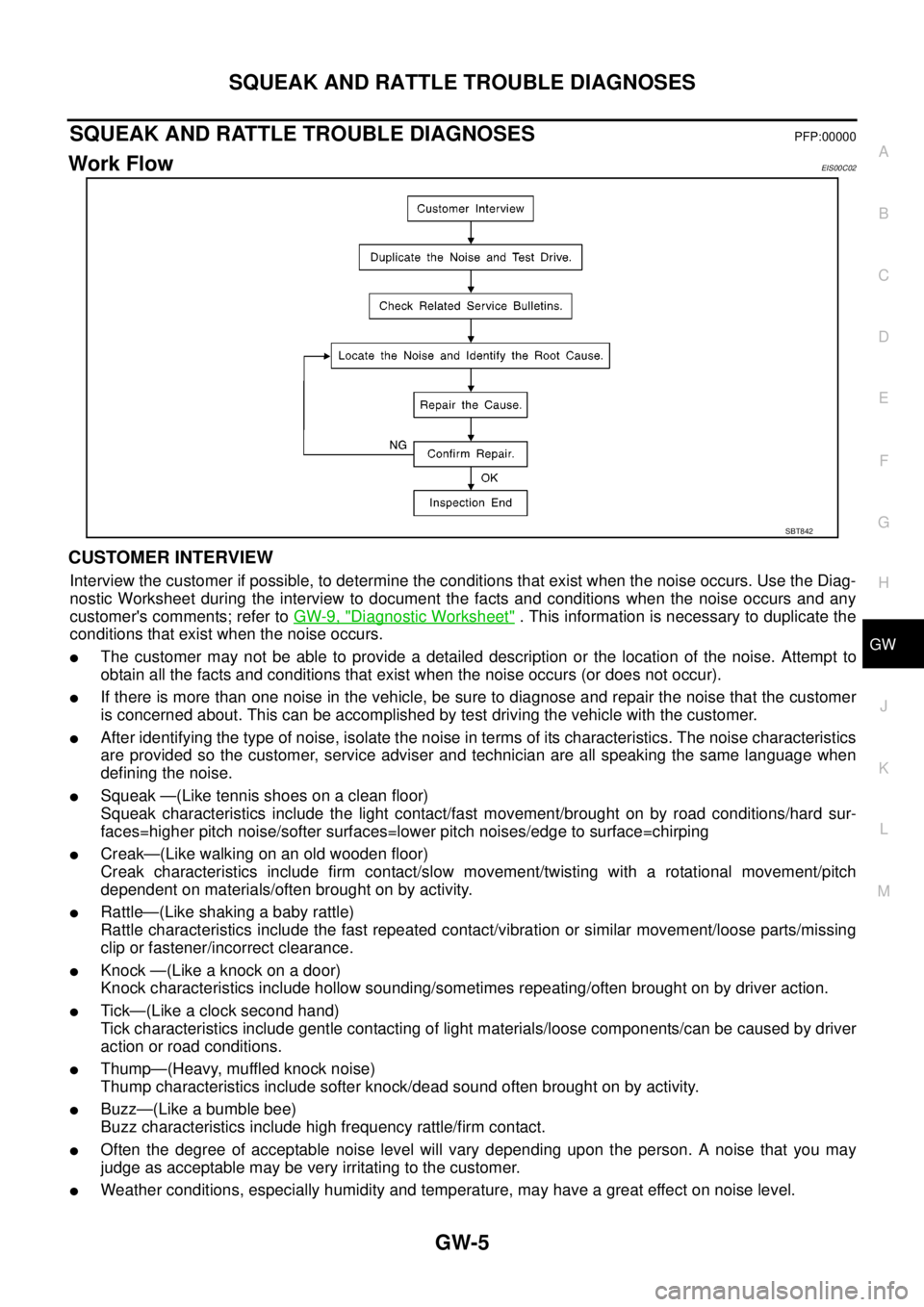
Work FlowEIS00C02
CUSTOMER INTERVIEW
Interview the customer if possible, to determine the conditions that exist when the noise occurs. Use the Diag-
nostic Worksheet during the interview to document the facts and conditions when the noise occurs and any
customer's comments; refer toGW-9, "
Diagnostic Worksheet". This information is necessary to duplicate the
conditions that exist when the noise occurs.
lThe customer may not be able to provide a detailed description or the location of the noise. Attempt to
obtain all the facts and conditions that exist when the noise occurs (or does not occur).
lIf there is more than one noise in the vehicle, be sure to diagnose and repair the noise that the customer
is concerned about. This can be accomplished by test driving the vehicle with the customer.
lAfter identifying the type of noise, isolate the noise in terms of its characteristics. The noise characteristics
are provided so the customer, service adviser and technician are all speaking the same language when
defining the noise.
lSqueak —(Like tennis shoes on a clean floor)
Squeak characteristics include the light contact/fast movement/brought on by road conditions/hard sur-
faces=higher pitch noise/softer surfaces=lower pitch noises/edge to surface=chirping
lCreak—(Like walking on an old wooden floor)
Creak characteristics include firm contact/slow movement/twisting with a rotational movement/pitch
dependent on materials/often brought on by activity.
lRattle—(Like shaking a baby rattle)
Rattle characteristics include the fast repeated contact/vibration or similar movement/loose parts/missing
clip or fastener/incorrect clearance.
lKnock—(Likeaknockonadoor)
Knock characteristics include hollow sounding/sometimes repeating/often brought on by driver action.
lTick—(Like a clock second hand)
Tick characteristics include gentle contacting of light materials/loose components/can be caused by driver
action or road conditions.
lThump—(Heavy, muffled knock noise)
Thump characteristics include softer knock/dead sound often brought on by activity.
lBuzz—(Like a bumble bee)
Buzz characteristics include high frequency rattle/firm contact.
lOften the degree of acceptable noise level will vary depending upon the person. A noise that you may
judge as acceptable may be very irritating to the customer.
lWeather conditions, especially humidity and temperature, may have a great effect on noise level.
SBT842