2005 NISSAN NAVARA clock
[x] Cancel search: clockPage 2858 of 3171
CHARGING SYSTEM
SC-25
C
D
E
F
G
H
I
J
L
MA
B
SC
InspectionEKS00MZH
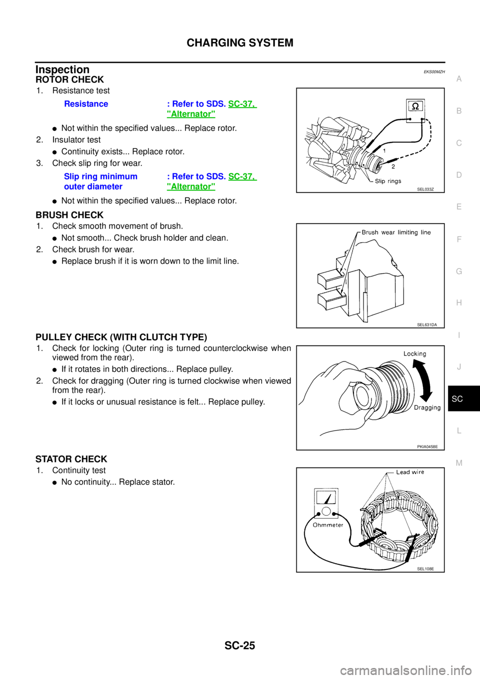
ROTOR CHECK
1. Resistance test
lNot within the specified values... Replace rotor.
2. Insulator test
lContinuity exists... Replace rotor.
3. Check slip ring for wear.
lNot within the specified values... Replace rotor.
BRUSH CHECK
1. Check smooth movement of brush.
lNot smooth... Check brush holder and clean.
2. Check brush for wear.
lReplace brush if it is worn down to the limit line.
PULLEY CHECK (WITH CLUTCH TYPE)
1. Check for locking (Outer ring is turned counterclockwise when
viewed from the rear).
lIf it rotates in both directions... Replace pulley.
2. Check for dragging (Outer ring is turned clockwise when viewed
from the rear).
lIf it locks or unusual resistance is felt... Replace pulley.
STATOR CHECK
1. Continuity test
lNo continuity... Replace stator.Resistance : Refer to SDS.SC-37,
"Alternator"
Slip ring minimum
outer diameter: Refer to SDS.SC-37,
"Alternator"SEL033Z
SEL631DA
PKIA0458E
SEL108E
Page 2875 of 3171
SE-4
SQUEAK AND RATTLE TROUBLE DIAGNOSES
SQUEAK AND RATTLE TROUBLE DIAGNOSES
PFP:00000
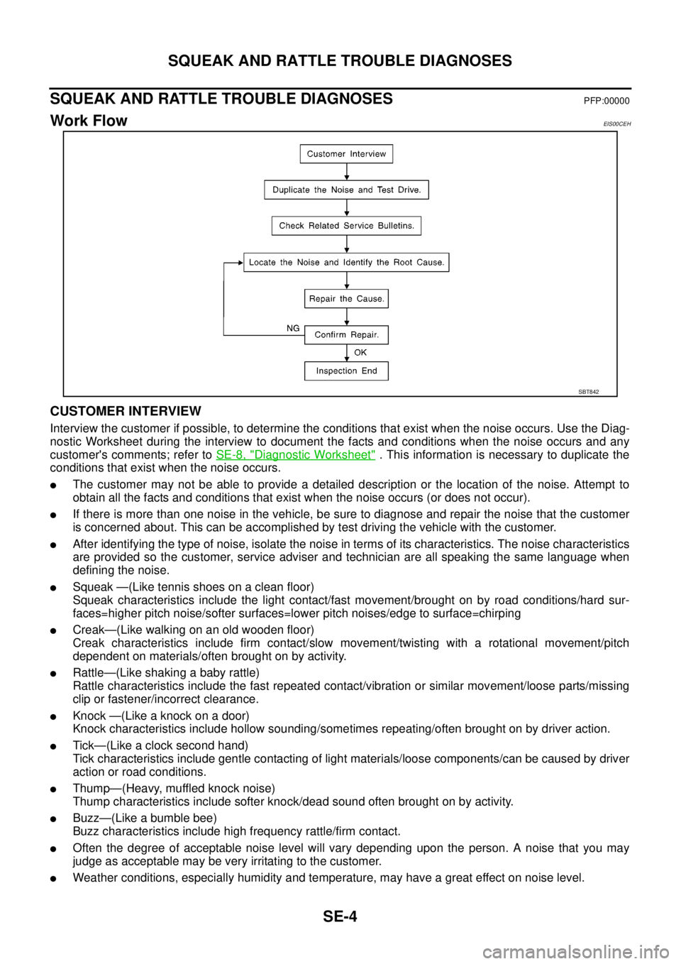
Work FlowEIS00CEH
CUSTOMER INTERVIEW
Interview the customer if possible, to determine the conditions that exist when the noise occurs. Use the Diag-
nostic Worksheet during the interview to document the facts and conditions when the noise occurs and any
customer's comments; refer toSE-8, "
Diagnostic Worksheet". This information is necessary to duplicate the
conditions that exist when the noise occurs.
lThe customer may not be able to provide a detailed description or the location of the noise. Attempt to
obtain all the facts and conditions that exist when the noise occurs (or does not occur).
lIf there is more than one noise in the vehicle, be sure to diagnose and repair the noise that the customer
is concerned about. This can be accomplished by test driving the vehicle with the customer.
lAfter identifying the type of noise, isolate the noise in terms of its characteristics. The noise characteristics
are provided so the customer, service adviser and technician are all speaking the same language when
defining the noise.
lSqueak —(Like tennis shoes on a clean floor)
Squeak characteristics include the light contact/fast movement/brought on by road conditions/hard sur-
faces=higher pitch noise/softer surfaces=lower pitch noises/edge to surface=chirping
lCreak—(Like walking on an old wooden floor)
Creak characteristics include firm contact/slow movement/twisting with a rotational movement/pitch
dependent on materials/often brought on by activity.
lRattle—(Like shaking a baby rattle)
Rattle characteristics include the fast repeated contact/vibration or similar movement/loose parts/missing
clip or fastener/incorrect clearance.
lKnock —(Like a knock on a door)
Knock characteristics include hollow sounding/sometimes repeating/often brought on by driver action.
lTick—(Like a clock second hand)
Tick characteristics include gentle contacting of light materials/loose components/can be caused by driver
action or road conditions.
lThump—(Heavy, muffled knock noise)
Thump characteristics include softer knock/dead sound often brought on by activity.
lBuzz—(Like a bumble bee)
Buzz characteristics include high frequency rattle/firm contact.
lOften the degree of acceptable noise level will vary depending upon the person. A noise that you may
judge as acceptable may be very irritating to the customer.
lWeather conditions, especially humidity and temperature, may have a great effect on noise level.
SBT842
Page 2948 of 3171
SPIRAL CABLE
SRS-39
C
D
E
F
G
I
J
K
L
MA
B
SRS
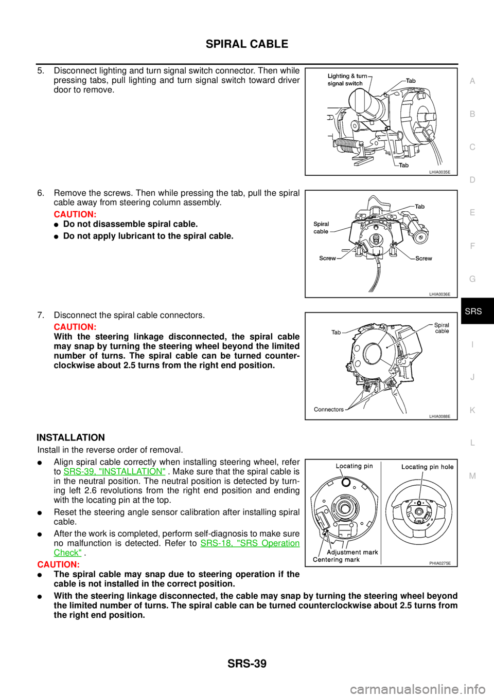
5. Disconnect lighting and turn signal switch connector. Then while
pressing tabs, pull lighting and turn signal switch toward driver
door to remove.
6. Remove the screws. Then while pressing the tab, pull the spiral
cable away from steering column assembly.
CAUTION:
lDo not disassemble spiral cable.
lDo not apply lubricant to the spiral cable.
7. Disconnect the spiral cable connectors.
CAUTION:
With the steering linkage disconnected, the spiral cable
may snap by turning the steering wheel beyond the limited
number of turns. The spiral cable can be turned counter-
clockwise about 2.5 turns from the right end position.
INSTALLATION
Install in the reverse order of removal.
lAlign spiral cable correctly when installing steering wheel, refer
toSRS-39, "
INSTALLATION". Make sure that the spiral cable is
in the neutral position. The neutral position is detected by turn-
ing left 2.6 revolutions from the right end position and ending
with the locating pin at the top.
lReset the steering angle sensor calibration after installing spiral
cable.
lAfter the work is completed, perform self-diagnosis to make sure
no malfunction is detected. Refer toSRS-18, "
SRS Operation
Check".
CAUTION:
lThe spiral cable may snap due to steering operation if the
cable is not installed in the correct position.
lWith the steering linkage disconnected, the cable may snap by turning the steering wheel beyond
the limited number of turns. The spiral cable can be turned counterclockwise about 2.5 turns from
the right end position.
LHIA0035E
LHIA0036E
LHIA0088E
PHIA0275E
Page 3006 of 3171
![NISSAN NAVARA 2005 Repair Workshop Manual TROUBLE DIAGNOSIS
TF-39
C
E
F
G
H
I
J
K
L
MA
B
TF
2WDSWITCH[ON/
OFF]Input condition from 4WD
shift switch4WD shift switch: 2WD ON
4WD shift switch: 4H and 4LO OFF
4H SWITCH [ON/OFF]Input condition fro NISSAN NAVARA 2005 Repair Workshop Manual TROUBLE DIAGNOSIS
TF-39
C
E
F
G
H
I
J
K
L
MA
B
TF
2WDSWITCH[ON/
OFF]Input condition from 4WD
shift switch4WD shift switch: 2WD ON
4WD shift switch: 4H and 4LO OFF
4H SWITCH [ON/OFF]Input condition fro](/manual-img/5/57362/w960_57362-3005.png)
TROUBLE DIAGNOSIS
TF-39
C
E
F
G
H
I
J
K
L
MA
B
TF
2WDSWITCH[ON/
OFF]Input condition from 4WD
shift switch4WD shift switch: 2WD ON
4WD shift switch: 4H and 4LO OFF
4H SWITCH [ON/OFF]Input condition from 4WD
shift switch4WD shift switch: 4H ON
4WD shift switch: 2WD and 4LO OFF
4L SWITCH [ON/OFF]Input condition from 4WD
shift switch4WD shift switch: 4LO ON
4WD shift switch: 2WD and 4H OFF
4L POSI SW [ON/OFF] Condition of 4LO switch
lVehicle stopped
lEngine running
lFor A/T models, A/T
selector lever “N” posi-
tion with brake pedal
depressed.
lFor M/T models, M/T
shift lever neutral posi-
tion with clutch and
brake pedal depressed.4WD shift switch: 4LO ON
Except the above OFF
ATP SWITCH [ON/OFF] Condition of ATP switch
lVehicle stopped
lEngine running
lA/T selector lever “N”
position with brake
pedal depressed.4WD shift switch:
4H to 4LO or 4LO to 4H
(While actuator motor is
operating.)ON
Except the above OFF
WAIT DETCT SW [ON/
OFF]Condition of wait detection
switch
lVehicle stopped
lEngine running
lFor A/T models, A/T
selector lever “N” posi-
tion with brake pedal
depressed.
lFor M/T models, M/T
shift lever neutral posi-
tion with clutch and
brake pedal depressed.4WD shift switch:
4H and 4LOON
4WD shift switch: 2WD OFF
4WD MODE [2H/4H/4L]Control status of 4WD
(Output condition of 4WD
shift indicator lamp and
4LO indicator lamp)4WD shift switch
(Engine running)2WD 2H
4H 4H
4LO 4L
VHCL/S COMP [km/h]
or [mph]Vehicle speedVehicle stopped 0 km/h (0 mph)
Vehicle running
CAUTION:
Check air pressure of tires under standard condi-
tion.Approximately
equal to the indica-
tion on speedome-
ter (Inside of±10%)
SHIFT ACT 1 [ON/OFF]Output condition to actua-
tor motor (clockwise)
lVehicle stopped
lEngine running
lFor A/T models, A/T
selector lever “N” posi-
tion with brake pedal
depressed.
lFor M/T models, M/T
shift lever neutral posi-
tion with clutch and
brake pedal depressed.4WD shift switch:
2WDto4Hor4Hto4LO
or 2WD to 4LOON
Except the above OFF Monitored item [Unit] Content Condition Display value
Page 3007 of 3171
![NISSAN NAVARA 2005 Repair Workshop Manual TF-40
TROUBLE DIAGNOSIS
SHIFT AC MON1 [ON/
OFF]Check signal for transfer
control unit signal output
lVehicle stopped
lEngine running
lFor A/T models, A/T
selector lever “N” posi-
tion with brake p NISSAN NAVARA 2005 Repair Workshop Manual TF-40
TROUBLE DIAGNOSIS
SHIFT AC MON1 [ON/
OFF]Check signal for transfer
control unit signal output
lVehicle stopped
lEngine running
lFor A/T models, A/T
selector lever “N” posi-
tion with brake p](/manual-img/5/57362/w960_57362-3006.png)
TF-40
TROUBLE DIAGNOSIS
SHIFT AC MON1 [ON/
OFF]Check signal for transfer
control unit signal output
lVehicle stopped
lEngine running
lFor A/T models, A/T
selector lever “N” posi-
tion with brake pedal
depressed.
lFor M/T models, M/T
shift lever neutral posi-
tion with clutch and
brake pedal depressed.4WD shift switch:
2WDto4Hor4Hto4LO
or 2WD to 4LOON
Except the above OFF
SHIFT ACT 2 [ON/OFF]Output condition to actua-
tor motor (counterclock-
wise)
lVehicle stopped
lEngine running
lFor A/T models, A/T
selector lever “N” posi-
tion with brake pedal
depressed.
lFor M/T models, M/T
shift lever neutral posi-
tion with clutch and
brake pedal depressed.4WD shift switch:
4LOto4Hor4Hto2WD
or 4LO to 2WDON
Except the above OFF
SHIFT AC MON2 [ON/
OFF]Check signal for transfer
control unit signal output
lVehicle stopped
lEngine running
lFor A/T models, A/T
selector lever “N” posi-
tion with brake pedal
depressed.
lFor M/T models, M/T
shift lever neutral posi-
tion with clutch and
brake pedal depressed.4WD shift switch:
4LOto4Hor4Hto2WD
or 4LO to 2WDON
Except the above OFF
SHIFT ACT/R MON
[ON/OFF]Operating condition of
actuator motor relay (inte-
grated in transfer control
unit)
lVehicle stopped
lEngine running
lFor A/T models, A/T
selector lever “N” posi-
tion with brake pedal
depressed.
lFor M/T models, M/T
shift lever neutral posi-
tion with clutch and
brake pedal depressed.When 4WD shift switch is
operatedON
When 4WD shift switch is
not operatedOFF
SHIFT POS SW1 [ON/
OFF]Condition of actuator posi-
tion switch 1
lVehicle stopped
lEngine running
lFor A/T models, A/T
selector lever “N” posi-
tion with brake pedal
depressed.
lFor M/T models, M/T
shift lever neutral posi-
tion with clutch and
brake pedal depressed.4WD shift switch:
2WD and 4LOON
4WD shift switch: 4H OFF
SHIFT POS SW2 [ON/
OFF]Condition of actuator posi-
tion switch 24WD shift switch: 4LO ON
4WD shift switch:
2WD and 4HOFF
SHIFT POS SW3 [ON/
OFF]Condition of actuator posi-
tion switch 34WD shift switch:
2WD and 4HON
4WD shift switch: 4LO OFF
SHIFT POS SW4 [ON/
OFF]Condition of actuator posi-
tion switch 44WD shift switch:
4H and 4LOON
4WD shift switch: 2WD OFF
4WD FAIL LAMP [ON/
OFF]4WD warning lamp condi-
tion4WD warning lamp: ON ON
4WD warning lamp: OFF OFF Monitored item [Unit] Content Condition Display value
Page 3014 of 3171
TROUBLE DIAGNOSIS
TF-47
C
E
F
G
H
I
J
K
L
MA
B
TF
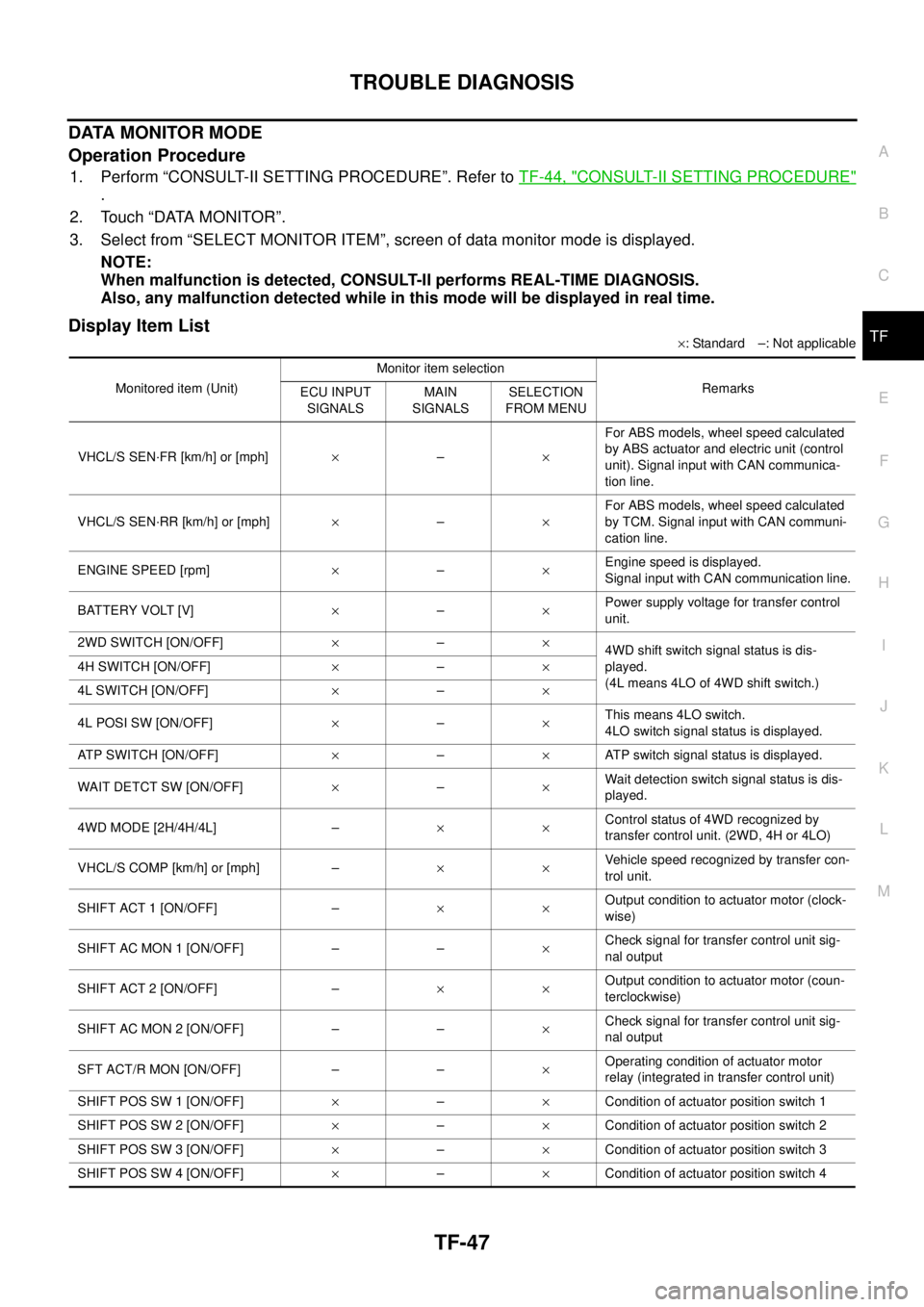
DATA MONITOR MODE
Operation Procedure
1. Perform “CONSULT-II SETTING PROCEDURE”. Refer toTF-44, "CONSULT-II SETTING PROCEDURE"
.
2. Touch “DATA MONITOR”.
3. Select from “SELECT MONITOR ITEM”, screen of data monitor mode is displayed.
NOTE:
When malfunction is detected, CONSULT-II performs REAL-TIME DIAGNOSIS.
Also, any malfunction detected while in this mode will be displayed in real time.
Display Item List
´: Standard –: Not applicable
Monitored item (Unit)Monitor item selection
Remarks
ECU INPUT
SIGNALSMAIN
SIGNALSSELECTION
FROM MENU
VHCL/S SEN·FR [km/h] or [mph]´–´For ABS models, wheel speed calculated
by ABS actuator and electric unit (control
unit). Signal input with CAN communica-
tion line.
VHCL/S SEN·RR [km/h] or [mph]´–´For ABS models, wheel speed calculated
by TCM. Signal input with CAN communi-
cation line.
ENGINE SPEED [rpm]´–´Engine speed is displayed.
Signal input with CAN communication line.
BATTERY VOLT [V]´–´Power supply voltage for transfer control
unit.
2WD SWITCH [ON/OFF]´–´
4WD shift switch signal status is dis-
played.
(4L means 4LO of 4WD shift switch.) 4H SWITCH [ON/OFF]´–´
4L SWITCH [ON/OFF]´–´
4L POSI SW [ON/OFF]´–´This means 4LO switch.
4LO switch signal status is displayed.
ATP SWITCH [ON/OFF]´–´ATP switch signal status is displayed.
WAIT DETCT SW [ON/OFF]´–´Wait detection switch signal status is dis-
played.
4WD MODE [2H/4H/4L] –´´Control status of 4WD recognized by
transfer control unit. (2WD, 4H or 4LO)
VHCL/S COMP [km/h] or [mph] –´´Vehicle speed recognized by transfer con-
trol unit.
SHIFT ACT 1 [ON/OFF] –´´Output condition to actuator motor (clock-
wise)
SHIFT AC MON 1 [ON/OFF] – –´Check signal for transfer control unit sig-
nal output
SHIFT ACT 2 [ON/OFF] –´´Output condition to actuator motor (coun-
terclockwise)
SHIFT AC MON 2 [ON/OFF] – –´Check signal for transfer control unit sig-
nal output
SFT ACT/R MON [ON/OFF] – –´Operating condition of actuator motor
relay (integrated in transfer control unit)
SHIFT POS SW 1 [ON/OFF]´–´Condition of actuator position switch 1
SHIFT POS SW 2 [ON/OFF]´–´Condition of actuator position switch 2
SHIFT POS SW 3 [ON/OFF]´–´Condition of actuator position switch 3
SHIFT POS SW 4 [ON/OFF]´–´Condition of actuator position switch 4
Page 3034 of 3171
TROUBLE DIAGNOSIS FOR SYSTEM
TF-67
C
E
F
G
H
I
J
K
L
MA
B
TF
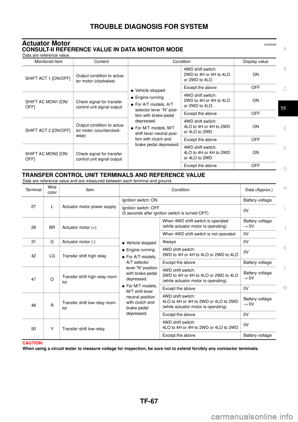
Actuator MotorEDS00326
CONSULT-II REFERENCE VALUE IN DATA MONITOR MODE
Data are reference value.
TRANSFER CONTROL UNIT TERMINALS AND REFERENCE VALUE
Data are reference value and are measured between each terminal and ground.
CAUTION:
When using a circuit tester to measure voltage for inspection, be sure not to extend forcibly any connector terminals.Monitored item Content Condition Display value
SHIFT ACT 1 [ON/OFF]Output condition to actua-
tor motor (clockwise)
lVehicle stopped
lEngine running
lFor A/T models, A/T
selector lever “N” posi-
tion with brake pedal
depressed.
lFor M/T models, M/T
shift lever neutral posi-
tion with clutch and
brake pedal depressed.4WD shift switch:
2WDto4Hor4Hto4LO
or 2WD to 4LOON
Except the above OFF
SHIFT AC MON1 [ON/
OFF]Check signal for transfer
control unit signal output4WD shift switch:
2WDto4Hor4Hto4LO
or 2WD to 4LOON
Except the above OFF
SHIFT ACT 2 [ON/OFF]Output condition to actua-
tor motor (counterclock-
wise)4WD shift switch:
4LO to 4H or 4H to 2WD
or 4LO to 2WDON
Except the above OFF
SHIFT AC MON2 [ON/
OFF]Check signal for transfer
control unit signal output4WD shift switch:
4LO to 4H or 4H to 2WD
or 4LO to 2WDON
Except the above OFF
TerminalWire
colorItem Condition Data (Approx.)
27 L Actuator motor power supplyIgnition switch: ON Battery voltage
Ignition switch: OFF
(5 seconds after ignition switch is turned OFF)0V
28 BR Actuator motor (+)
lVehicle stopped
lEngine running
lFor A/T models,
A/T selector
lever “N” position
with brake pedal
depressed.
lFor M/T models,
M/T shift lever
neutral position
with clutch and
brake pedal
depressed.When 4WD shift switch is operated
(while actuator motor is operating)Battery voltage
®0V
When 4WD shift switch is not operated 0V
31 G Actuator motor (-) Always 0V
42 LG Transfer shift high relay4WD shift switch:
2WD to 4H or 4H to 4LO or 2WD to 4LO0V
Except the above Battery voltage
47 OTransfer shift high relay moni-
tor4WD shift switch:
2WD to 4H or 4H to 4LO or 2WD to 4LO
(while actuator motor is operating)Battery voltage
®0V
Except the above 0V
48 RTransfer shift low relay moni-
tor4WD shift switch:
4LO to 4H or 4H to 2WD or 4LO to 2WD
(while actuator motor is operating)Battery voltage
®0V
Except the above 0V
50 Y Transfer shift low relay4WD shift switch:
4LO to 4H or 4H to 2WD or 4LO to 2WD0V
Except the above Battery voltage
Page 3040 of 3171
TROUBLE DIAGNOSIS FOR SYSTEM
TF-73
C
E
F
G
H
I
J
K
L
MA
B
TF
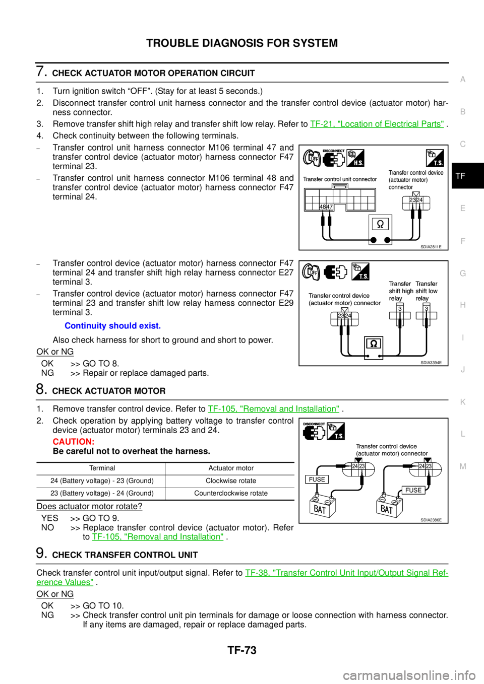
7.CHECK ACTUATOR MOTOR OPERATION CIRCUIT
1. Turn ignition switch “OFF”. (Stay for at least 5 seconds.)
2. Disconnect transfer control unit harness connector and the transfer control device (actuator motor) har-
ness connector.
3. Remove transfer shift high relay and transfer shift low relay. Refer toTF-21, "
Location of Electrical Parts".
4. Check continuity between the following terminals.
–Transfer control unit harness connector M106 terminal 47 and
transfer control device (actuator motor) harness connector F47
terminal 23.
–Transfer control unit harness connector M106 terminal 48 and
transfer control device (actuator motor) harness connector F47
terminal 24.
–Transfer control device (actuator motor) harness connector F47
terminal 24 and transfer shift high relay harness connector E27
terminal 3.
–Transfer control device (actuator motor) harness connector F47
terminal 23 and transfer shift low relay harness connector E29
terminal 3.
Also check harness for short to ground and short to power.
OK or NG
OK >> GO TO 8.
NG >> Repair or replace damaged parts.
8.CHECK ACTUATOR MOTOR
1. Remove transfer control device. Refer toTF-105, "
Removal and Installation".
2. Check operation by applying battery voltage to transfer control
device (actuator motor) terminals 23 and 24.
CAUTION:
Be careful not to overheat the harness.
Does actuator motor rotate?
YES >> GO TO 9.
NO >> Replace transfer control device (actuator motor). Refer
toTF-105, "
Removal and Installation".
9.CHECK TRANSFER CONTROL UNIT
Check transfer control unit input/output signal. Refer toTF-38, "
Transfer Control Unit Input/Output Signal Ref-
erence Values".
OK or NG
OK >> GO TO 10.
NG >> Check transfer control unit pin terminals for damage or loose connection with harness connector.
If any items are damaged, repair or replace damaged parts.
SDIA2811E
Continuity should exist.
SDIA3394E
Terminal Actuator motor
24 (Battery voltage) - 23 (Ground) Clockwise rotate
23 (Battery voltage) - 24 (Ground) Counterclockwise rotate
SDIA2386E