2005 NISSAN NAVARA clock
[x] Cancel search: clockPage 488 of 3171

ATC-154
SERVICE DATA AND SPECIFICATIONS (SDS)
SERVICE DATA AND SPECIFICATIONS (SDS)
PFP:00030
Service Data and Specifications (SDS)EJS006D5
COMPRESSOR
LUBRICANT
REFRIGERANT
ENGINE IDLING SPEED
Refer toEC-38, "Basic Inspection".
BELT TENSION
Refer toEM-13, "Deflection Adjustment".
Make ZEXEL VALEO CLIMATE CONTROL
Model DKS-17D
Type Swash plate
Displacement
175.5 cm
3(10.7 in3)/revolution
Cylinder bore´stroke 30.5 mm (1.20 in) x 24.0 mm (0.94 in)
Direction of rotation Clockwise (viewed from drive end)
Drive belt Poly V
Make ZEXEL VALEO CLIMATE CONTROL
Model DKS-17D
Name Genuine NISSAN A/C System Lubricant Type S (DH-PS)
Part number KLH00-PAGS0
CapacityWithout rear A/C
180 m (6.3 Imp fl oz)
With rear A/C
210 m (7.4 Imp fl oz)
Type HFC 134a (R-134a)
CapacityWithout rear A/C 0.70±0.05 kg (1.54±0.11 lb)
With rear A/C 0.85±0.05 kg (1.87±0.11 lb)
Page 590 of 3171

BL-6
SQUEAK AND RATTLE TROUBLE DIAGNOSES
SQUEAK AND RATTLE TROUBLE DIAGNOSES
PFP:00000
Work FlowEIS00DI2
CUSTOMER INTERVIEW
Interview the customer if possible, to determine the conditions that exist when the noise occurs. Use the Diag-
nostic Worksheet during the interview to document the facts and conditions when the noise occurs and any
customer's comments; refer toBL-10, "
Diagnostic Worksheet". This information is necessary to duplicate the
conditions that exist when the noise occurs.
lThe customer may not be able to provide a detailed description or the location of the noise. Attempt to
obtain all the facts and conditions that exist when the noise occurs (or does not occur).
lIf there is more than one noise in the vehicle, be sure to diagnose and repair the noise that the customer
is concerned about. This can be accomplished by test driving the vehicle with the customer.
lAfter identifying the type of noise, isolate the noise in terms of its characteristics. The noise characteristics
are provided so the customer, service adviser and technician are all speaking the same language when
defining the noise.
lSqueak —(Like tennis shoes on a clean floor)
Squeak characteristics include the light contact/fast movement/brought on by road conditions/hard sur-
faces=higher pitch noise/softer surfaces=lower pitch noises/edge to surface=chirping
lCreak—(Like walking on an old wooden floor)
Creak characteristics include firm contact/slow movement/twisting with a rotational movement/pitch
dependent on materials/often brought on by activity.
lRattle—(Like shaking a baby rattle)
Rattle characteristics include the fast repeated contact/vibration or similar movement/loose parts/missing
clip or fastener/incorrect clearance.
lKnock —(Like a knock on a door)
Knock characteristics include hollow sounding/sometimes repeating/often brought on by driver action.
lTick—(Like a clock second hand)
Tick characteristics include gentle contacting of light materials/loose components/can be caused by driver
action or road conditions.
lThump—(Heavy, muffled knock noise)
Thump characteristics include softer knock/dead sound often brought on by activity.
lBuzz—(Like a bumble bee)
Buzz characteristics include high frequency rattle/firm contact.
lOften the degree of acceptable noise level will vary depending upon the person. A noise that you may
judge as acceptable may be very irritating to the customer.
lWeather conditions, especially humidity and temperature, may have a great effect on noise level.
SBT842
Page 793 of 3171

BRAKE PEDAL
BR-7
C
D
E
G
H
I
J
K
L
MA
B
BR
ADJUSTMENT
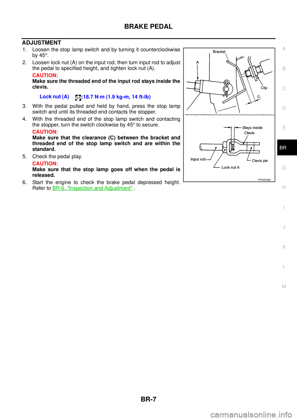
1. Loosen the stop lamp switch and by turning it counterclockwise
by 45°.
2. Loosen lock nut (A) on the input rod, then turn input rod to adjust
the pedal to specified height, and tighten lock nut (A).
CAUTION:
Make sure the threaded end of the input rod stays inside the
clevis.
3. With the pedal pulled and held by hand, press the stop lamp
switch and until its threaded end contacts the stopper.
4. With the threaded end of the stop lamp switch and contacting
the stopper, turn the switch clockwise by 45°to secure.
CAUTION:
Make sure that the clearance (C) between the bracket and
threaded end of the stop lamp switch and are within the
standard.
5. Check the pedal play.
CAUTION:
Make sure that the stop lamp goes off when the pedal is
released.
6. Start the engine to check the brake pedal depressed height.
Refer toBR-6, "
Inspection and Adjustment". Lock nut (A)
:18.7 N·m (1.9 kg-m, 14 ft-lb)
PFIA0436E
Page 799 of 3171

BRAKE TUBE AND HOSE
BR-13
C
D
E
G
H
I
J
K
L
MA
B
BR
CAUTION:
lAll brake tubes and hoses must be free from excessive bending, twisting and pulling.
lMake sure that there is no interference with other parts when turning steering both clockwise and
counterclockwise.
lBrake tube and hose is an important safety part. Always disassemble the parts and retighten their
fittings, if a brake fluid leak is detected. Replace applicable part with a new one, if damaged part is
detected.
lBe careful not to splash brake fluid on painted areas; it may cause paint damage. If brake fluid is
splashed on painted surfaces of body, immediately wipe off them and wash it away with water.
lDo not bend or twist brake hose sharply, or strongly pull it.
lCover the open end of brake tube and hoses when disconnecting to prevent entrance of dirt.
lRefill with new brake fluid “DOT 3” or “DOT 4”.
lNever reuse drained brake fluid.
Removal and Installation of Front Brake Tube and Brake HoseEFS005SM
REMOVAL
1. Drain brake fluid. Refer toBR-10, "Drain and Refill".
2. Using a flare nut wrench, disconnect brake tube from brake hose.
3. Remove union bolt and remove brake hose from caliper assembly.
4. Remove lock plate and remove brake hose from vehicle.
INSTALLATION
1. Assemble the union bolt and copper washers to the brake hose.
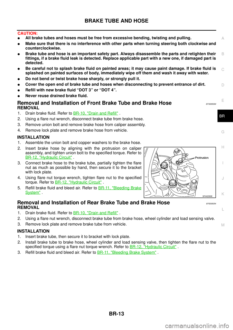
2. Insert brake hose by aligning with the protrusion on caliper
assembly, and tighten union bolt to the specified torque. Refer to
BR-12, "
Hydraulic Circuit".
3. Connect brake hose to the brake tube, partially tighten the flare
nut as much as possible by hand, then secure it to the bracket
with lock plate.
4. Using flare nut torque wrench, tighten flare nut to the specified
torque. Refer toBR-12, "
Hydraulic Circuit".
5. Refill brake fluid and bleed air. Refer toBR-11, "
Bleeding Brake
System".
Removal and Installation of Rear Brake Tube and Brake HoseEFS005SN
REMOVAL
1. Drain brake fluid. Refer toBR-10, "Drain and Refill".
2. Using a flare nut wrench, disconnect brake tube from brake hose, wheel cylinder and load sensing valve.
3. Remove lock plate and remove brake tube from vehicle.
INSTALLATION
1. Insert brake tube, then secure it to bracket with lock plate.
2. Install brake tube to brake hose, wheel cylinder and load sensing valve, then tighten the flare nut to the
specified torque using a flare nut torque wrench. Refer toBR-12, "
Hydraulic Circuit".
3. Refill brake fluid and bleed air. Refer toBR-11, "
Bleeding Brake System".
SFIA2290E
Page 911 of 3171

DI-1
DRIVER INFORMATION SYSTEM
K ELECTRICAL
CONTENTS
C
D
E
F
G
H
I
J
L
M
SECTIONDI
A
B
DI
DRIVER INFORMATION SYSTEM
PRECAUTION ............................................................ 3
Precautions for Supplemental Restraint System
(SRS)“AIRBAG”and“SEATBELTPRE-TEN-
SIONER” .................................................................. 3
Wiring Diagrams and Trouble Diagnosis .................. 3
COMBINATION METERS ........................................... 4
System Description .................................................. 4
UNIFIED METER CONTROL UNIT ...................... 4
POWER SUPPLY AND GROUND CIRCUIT ........ 4
SPEEDOMETER ................................................... 4
TACHOMETER ..................................................... 4
WATER TEMPERATURE GAUGE ........................ 4
FUEL GAUGE ....................................................... 5
ODO/TRIP METER ............................................... 5
TRIP COMPUTER ................................................ 5
ENGINE OIL MAINTENANCE INFORMATION..... 6
METER ILLUMINATION CONTROL ..................... 6
CLOCK .................................................................. 6
AMBIENT AIR TEMPERATURE INDICATION ...... 6
Component Parts and Harness Connector Location..... 7
Arrangement of Combination Meter ......................... 8
Internal Circuit .......................................................... 9
Wiring Diagram — METER — ................................ 10
Terminals and Reference Value for Combination
Meter ...................................................................... 12
Self-Diagnosis Mode of Combination Meter ........... 13
FUNCTION .......................................................... 13
OPERATION PROCEDURE ............................... 13
TEST ITEM ......................................................... 13
CONSULT-II Function (METER) ............................. 15
CONSULT-II BASIC OPERATION ....................... 15
SELF-DIAG RESULTS ........................................ 16
DATA MONITOR ................................................. 17
Trouble Diagnosis .................................................. 18
HOW TO PERFORM TROUBLE DIAGNOSIS ... 18
PRELIMINARY CHECK ...................................... 19
Symptom Chart ...................................................... 19
Power Supply and Ground Circuit Inspection ........ 19
Vehicle Speed Signal Inspection ............................ 20
Engine Speed Signal Inspection ............................ 21Engine Coolant Temperature Signal Inspection ..... 21
Fuel Level Sensor Signal Inspection ...................... 22
Ambient Sensor Signal Inspection .......................... 24
Fuel Gauge Fluctuates, Indicates Wrong Value, or
Varies ...................................................................... 25
Fuel Gauge Does Not Move to Full position ........... 25
DTC [U1000] CAN Communication Circuit ............. 26
DTC [B2205] Vehicle Speed Circuit ........................ 26
Electrical Components Inspection .......................... 27
FUEL LEVEL SENSOR UNIT CHECK ................ 27
AMBIENT SENSOR CHECK ............................... 27
Removal and Installation of Combination Meter ..... 27
WARNING LAMPS .................................................... 28
System Description ................................................. 28
OIL PRESSURE WARNING LAMP ..................... 28
Component Parts and Harness Connector Location... 28
Schematic ............................................................... 29
Wiring Diagram — WARN — .................................. 30
A/T MODELS ....................................................... 30
M/T MODELS ...................................................... 37
Oil Pressure Warning Lamp Stays Off (Ignition
Switch ON) ............................................................. 44
Oil Pressure Warning Lamp Does Not Turn Off (Oil
Pressure Is Normal) ................................................ 45
Oil Pressure Warning Lamp Keeps Blinking (Oil
Level Is Normal) ..................................................... 46
Component Inspection ............................................ 47
OIL PRESSURE SWITCH ................................... 47
OIL LEVEL SENSOR .......................................... 47
A/T INDICATOR ........................................................ 48
System Description ................................................. 48
Wiring Diagram — AT/IND — ................................. 49
A/T Indicator Does Not Illuminate ........................... 50
WARNING CHIME ..................................................... 51
System Description ................................................. 51
POWER SUPPLY AND GROUND CIRCUIT ....... 51
LIGHT WARNING CHIME ................................... 51
KEY REMINDER WARNING CHIME .................. 51
LOW-FUEL WARNING CHIME ........................... 51
SEAT BELT WARNING CHIME ........................... 52
Page 914 of 3171

DI-4
COMBINATION METERS
COMBINATION METERS
PFP:24814
System DescriptionEKS00L8E
UNIFIED METER CONTROL UNIT
lSpeedometer, odo/trip meter, tachometer, fuel gauge and water temperature gauge are controlled by the
unified meter control unit, which is built into the combination meter.
lWarning lamp and indicator lamp are controlled by signals drawn from each unit with CAN communication
and components connected directly to the combination meter.
lOdo/trip meter display is included in the combination meter, which displays odometer, trip-meter, vehicle
information (trip computer, engine oil maintenance information)
*and A/T position*.
*: Vehicles with each system only.
lClock display is included in the combination meter, which displays current time, ambient air temperature*
and 4WD indicator*.
*: Vehicles with each system only.
lUnified meter control unit corresponds a CONSULT-II function (self-diagnosis results and data monitor).
lThe following items can be checked during self-diagnosis mode.
–Sweep of gauges pointer
–Present gauge values
–Odo/trip meter display and clock display segments
–Condition of warning lamps/indicator lamps controlled by unified meter control unit
–Battery voltage
–Driver's seat belt buckle switch status
–CPU status of unified meter control unit
POWER SUPPLY AND GROUND CIRCUIT
Power is supplied at all times
lthrough 10A fuse [No.19, located in the fuse block (J/B)]
lto combination meter terminal 3.
With the ignition switch in the ON or START position, power is supplied
lthrough 10A fuse [No.14, located in the fuse block (J/B)]
lto combination meter terminal 16.
Ground is supplied
lto combination meter terminals 13 and 23
lthrough grounds M21, M80 and M83.
SPEEDOMETER
The speedometer indicates the vehicle speed.
lABS actuator and electric unit (control unit) converses a pulse signal from wheel sensor to vehicle speed
signal, and transmits vehicle speed signal to combination meter with CAN communication.
lCombination meter converses the vehicle speed signal to angle signal, and commands to speedometer.
TACHOMETER
The tachometer indicates engine speed in revolutions per minute (rpm).
lECM converses a signal from crank position sensor to engine speed signal, and transmits to combination
meter with CAN communication.
lCombination meter converses the engine speed signal to angle signal, and commands to tachometer.
WATER TEMPERATURE GAUGE
The water temperature gauge indicates the engine coolant temperature.
lECM converses a signal from water temperature sensor to engine coolant temperature signal, and trans-
mits to combination meter with CAN communication.
lCombination meter converses the engine coolant temperature signal to angle signal, and commands to
water temperature gauge.
Page 916 of 3171

DI-6
COMBINATION METERS
ENGINE OIL MAINTENANCE INFORMATION
lEngine oil maintenance information displays maintenance intervals of engine oil.
lWith ignition switch ON position, engine oil maintenance information is displayed on odo/trip meter display
for 5 seconds.
NOTE:
Refer to Owner's Manual for setting.
METER ILLUMINATION CONTROL
When the lighting switch is turned ON, the odo/trip meter switch (1)
can be used to adjust the brightness of the combination meter illumi-
nation.
CLOCK
With ignition switch ON position, combination meter displays clock
on clock display. Time can be adjusted by clock switch (1). Clock can
be adjusted to 12-hour or 24-hour cycle clock.
NOTE:
If the battery cable is disconnected, the clock displays the time 12:00
in 12-hour mode.
AMBIENT AIR TEMPERATURE INDICATION
Combination meter displays ambient air temperature on clock display.
With ignition switch ON, “°C” blinks for a while. Ambient air temperature indication can be selected between
Centigrade and Fahrenheit.
Combination meter reads ambient air temperature signal from ambient sensor.
Signal is supplied
lfrom combination meter terminal 49
lthrough ambient sensor terminals 1 and 2
lto combination meter terminal 50.
When a temperature detected by sensor rises, combination meter controls increase of the indicated tempera-
ture depending on engine heat and other effective factors.
lIf the vehicle speed is more than 20 km/h, the indicated temperature rises according to the vehicle speed.
lIf the vehicle speed is less than 20 km/h, the indicated temperature is maintained.
When a temperature detected by sensor falls, the temperature is indicated immediately.
NOTE:
The range indicated on the display is between-30 and 60°C for Centigrade or between-22 and 99°Ffor
Fahrenheit.
lWhen the temperature is from-40°C(-40°F) to-30°C(-22°F), “--°C” is indicated on the display as
over range.
lWhen the temperature is under-40°C(-40°F) or over 60°C(140°F), nothing is indicated.
lWhen indicated temperature becomes less than 3°C(37°F), ambient air temperature indication blinks
warning. After blinking for 20 seconds, only “°C” blinks. At more than 4°C(39°F) the display stops blink-
ing.
SKIB4848E
PKIC1129E
Page 923 of 3171

COMBINATION METERS
DI-13
C
D
E
F
G
H
I
J
L
MA
B
DI
Self-Diagnosis Mode of Combination MeterEKS00L8K
FUNCTION
The following items can be checked during self-diagnosis mode.
lSweep of gauges pointer
lPresent gauge data values
lOdo/trip meter display and clock display segments
lCondition of warning lamps/indicator lamps controlled by unified meter control unit
lBattery voltage
lDriver's seat belt buckle switch status
lCPU of unified meter control unit status
OPERATION PROCEDURE
To initiate combination meter self-diagnosis mode, refer to the following procedure.
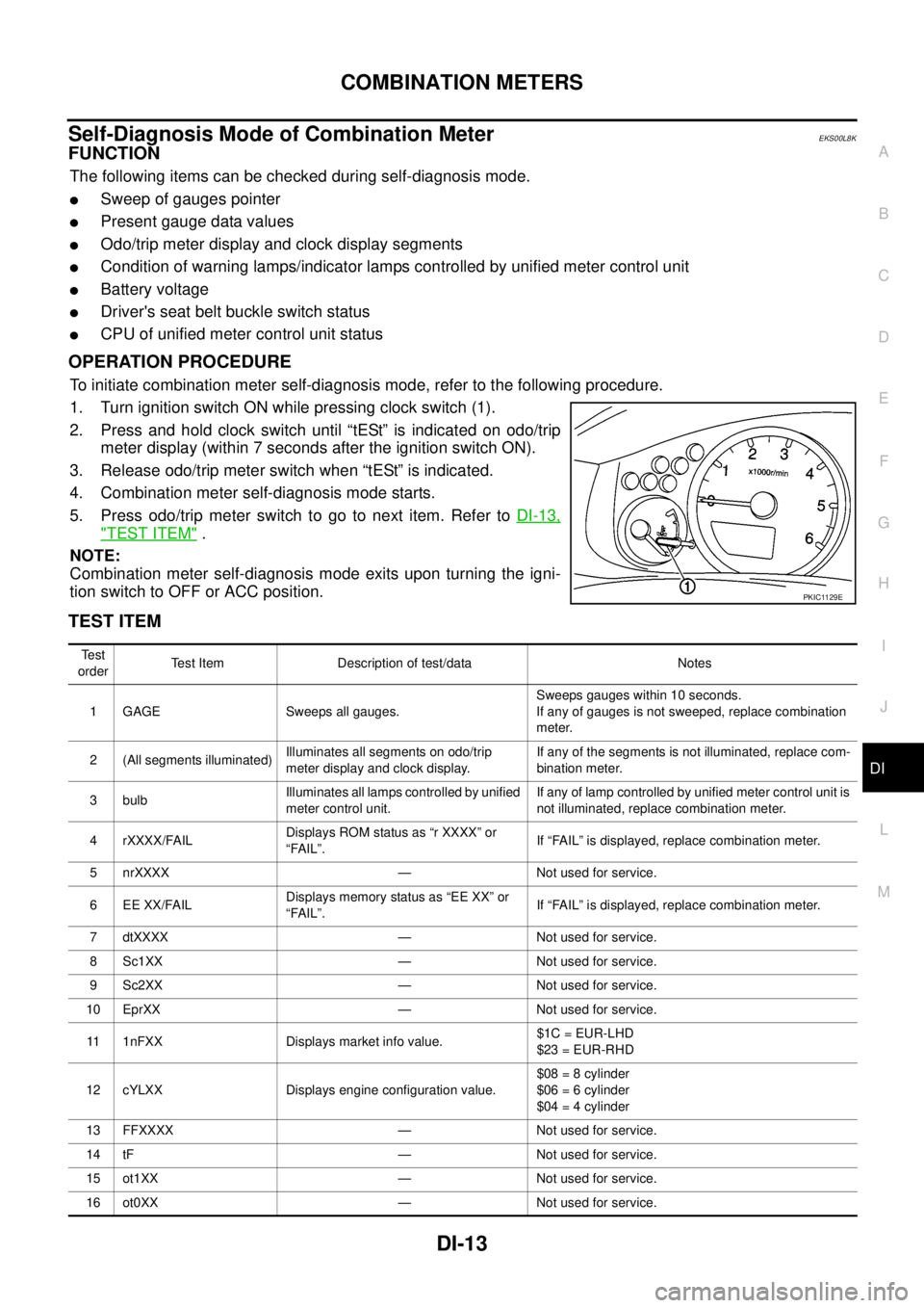
1. Turn ignition switch ON while pressing clock switch (1).
2. Press and hold clock switch until “tESt” is indicated on odo/trip
meter display (within 7 seconds after the ignition switch ON).
3. Release odo/trip meter switch when “tESt” is indicated.
4. Combination meter self-diagnosis mode starts.
5. Pressodo/tripmeterswitchtogotonextitem.RefertoDI-13,
"TEST ITEM".
NOTE:
Combination meter self-diagnosis mode exits upon turning the igni-
tion switch to OFF or ACC position.
TEST ITEM
PKIC1129E
Te s t
orderTest Item Description of test/data Notes
1 GAGE Sweeps all gauges.Sweeps gauges within 10 seconds.
If any of gauges is not sweeped, replace combination
meter.
2 (All segments illuminated)Illuminates all segments on odo/trip
meter display and clock display.If any of the segments is not illuminated, replace com-
bination meter.
3 bulbIlluminates all lamps controlled by unified
meter control unit.If any of lamp controlled by unified meter control unit is
not illuminated, replace combination meter.
4 rXXXX/FAILDisplays ROM status as “r XXXX” or
“FAIL”.If “FAIL” is displayed, replace combination meter.
5 nrXXXX — Not used for service.
6 EE XX/FAILDisplays memory status as “EE XX” or
“FAIL”.If “FAIL” is displayed, replace combination meter.
7 dtXXXX — Not used for service.
8 Sc1XX — Not used for service.
9 Sc2XX — Not used for service.
10 EprXX — Not used for service.
11 1nFXX Displays market info value.$1C = EUR-LHD
$23 = EUR-RHD
12 cYLXX Displays engine configuration value.$08 = 8 cylinder
$06 = 6 cylinder
$04 = 4 cylinder
13 FFXXXX — Not used for service.
14 tF — Not used for service.
15 ot1XX — Not used for service.
16 ot0XX — Not used for service.