2005 NISSAN NAVARA fuel type
[x] Cancel search: fuel typePage 493 of 3171

SYSTEM DESCRIPTION
AV-5
C
D
E
F
G
H
I
J
L
MA
B
AV
Personal Audio Setting
The radio is designed to store several settings (volume, bass, treble, preset stations) with every NATS ignition
key used. Up to a maximum of 4 NATS keys can be registered. During the communication mentioned under
“Anti-Theft System”, the radio will recognize the used ignition key and select the accompanying settings.
VEHICLE INFORMATION SYSTEM
lThe status of audio system, fuel consumption, rear view monitor and navigation system are displayed.
lNAVI control unit receives the data signal from ECM, combination meter via CAN communication. It calcu-
lates the values of fuel economy, and trip computer from the received information and displays them.
NAVIGATION SYSTEM
Refer to Owner's Manual or navigation system Owner's Manual for navigation system operating instructions.
Location Detection Principle
The navigation system periodically calculates the vehicle's current
position according to the following three signals:
lTravel distance of the vehicle as determined by the vehicle
speed sensor
lTurning angle of the vehicle as determined by the gyroscope
(angular velocity sensor)
lDirection of vehicle travel as determined by the GPS antenna
(GPS information)
The current position of the vehicle is then identified by comparing the
calculated vehicle position with map data read from the map DVD-
ROM, which is stored in the DVD-ROM drive (map-matching), and
indicated on the screen as a vehicle mark. More accurate data is judged and used by comparing vehicle posi-
tion detection results found by the GPS with the result by map-matching.
The current vehicle position will be calculated by detecting the dis-
tance the vehicle moved from the previous calculation point and its
direction.
lTravel distance
Travel distance calculations are based on the vehicle speed
sensor input signal. Therefore, the calculation may become
incorrect as the tires wear down. To prevent this, an automatic
distance correction function has been adopted.
lTravel direction
Change in the travel direction of the vehicle is calculated by a
gyroscope (angular velocity sensor) and a GPS antenna (GPS
information). They have both advantages and disadvantages.
More accurate traveling direction is detected because priorities are set for the signals from these two
devices according to the situation.
No communication from IMMU to radio 1. If NATS is malfunctioning, check NATS
system.
2. After NATS is repaired, reset radio to
NEW state by authorized representative
of Clarion.After switching on the radio, the radio will
display “SECURE” after 1 minute. Further
use of radio is impossible until communica-
tion is established again, or after radio is
reset by authorized representative of Clar-
ion.
When initialized between ECM and IMMU. Radio needs to be reset to NEW status by
authorized representative of Clarion.After switching on the radio, it will display
“SECURE” after 1 minute. Item Service procedure Description
SKIB1058E
Type Advantage Disadvantage
Gyroscope
(angular velocity sensor)Can detect the vehicle's turning angle
quite accurately.Direction errors may accumulate when vehicle is
driven for long distances without stopping.
GPS antenna
(GPS information)Can detect the vehicle's travel direction
(North/South/East/West).Correct direction cannot be detected when vehi-
cle speed is low.
SEL684V
Page 990 of 3171

EC-10
PRECAUTIONS
PRECAUTIONS
PFP:00001
Precautions for Supplemental Restraint System (SRS) “AIR BAG” and “SEAT
BELT PRE-TENSIONER”
EBS01KC5
The Supplemental Restraint System such as “AIR BAG” and “SEAT BELT PRE-TENSIONER”, used along
with a front seat belt, helps to reduce the risk or severity of injury to the driver and front passenger for certain
types of collision. Information necessary to service the system safely is included in the SRS and SB section of
this Service Manual.
WARNING:
lTo avoid rendering the SRS inoperative, which could increase the risk of personal injury or death
in the event of a collision which would result in air bag inflation, all maintenance must be per-
formed by an authorized NISSAN/INFINITI dealer.
lImproper maintenance, including incorrect removal and installation of the SRS, can lead to per-
sonal injury caused by unintentional activation of the system. For removal of Spiral Cable and Air
Bag Module, see the SRS section.
lDo not use electrical test equipment on any circuit related to the SRS unless instructed to in this
Service Manual. SRS wiring harnesses can be identified by yellow and/or orange harnesses or
harness connectors.
On Board Diagnostic (OBD) System of EngineEBS01KC6
The ECM has an on board diagnostic system. It will light up the malfunction indicator (MI) to warn the driver of
a malfunction causing emission deterioration.
CAUTION:
lBe sure to turn the ignition switch OFF and disconnect the battery negative cable before any
repair or inspection work. The open/short circuit of related switches, sensors, solenoid valves,
etc. will cause the MI to light up.
lBe sure to connect and lock the connectors securely after work. A loose (unlocked) connector will
cause the MI to light up due to the open circuit. (Be sure the connector is free from water, grease,
dirt, bent terminals, etc.)
lCertain systems and components, especially those related to OBD, may use a new style slide-
locking type harness connector. For description and how to disconnect, refer toPG-75, "
HAR-
NESS CONNECTOR".
lBe sure to route and secure the harnesses properly after work. The interference of the harness
with a bracket, etc. may cause the MI to light up due to the short circuit.
lBe sure to connect rubber tubes properly after work. A misconnected or disconnected rubber tube
may cause the MI to light up due to the malfunction of the fuel system, etc.
lBe sure to erase the unnecessary malfunction information (repairs completed) from the ECM
before returning the vehicle to the customer.
PrecautionsEBS01KC7
lAlways use a 12 volt battery as power source.
lDo not attempt to disconnect battery cables while engine is
running.
lBefore connecting or disconnecting the ECM harness con-
nector, turn ignition switch OFF and disconnect battery
negative cable. Failure to do so may damage the ECM
because battery voltage is applied to ECM even if ignition
switch is turned off.
lBefore removing parts, turn ignition switch OFF and then
disconnect battery negative cable.
SEF289H
Page 997 of 3171

ENGINE CONTROL SYSTEM
EC-17
C
D
E
F
G
H
I
J
K
L
MA
EC
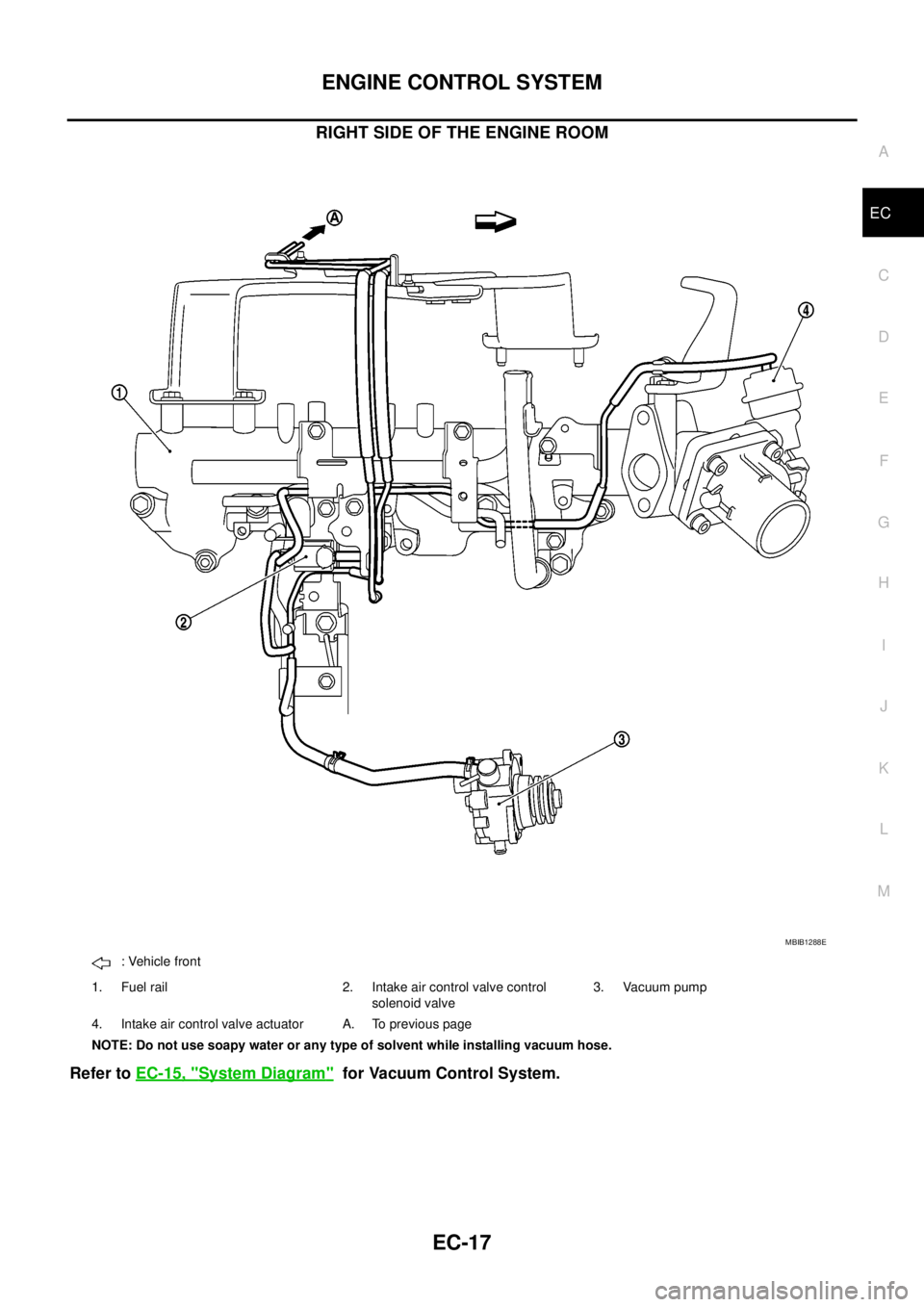
RIGHT SIDE OF THE ENGINE ROOM
Refer toEC-15, "System Diagram"for Vacuum Control System.
MBIB1288E
: Vehicle front
1. Fuel rail 2. Intake air control valve control
solenoid valve3. Vacuum pump
4. Intake air control valve actuator A. To previous page
NOTE: Do not use soapy water or any type of solvent while installing vacuum hose.
Page 998 of 3171

EC-18
ENGINE CONTROL SYSTEM
System Chart
EBS01KCD
*1: The input signal is sent to the ECM through CAN communication line.
*2: The output signal is sent from the ECM through CAN communication line.
Fuel Injection Control SystemEBS01KCE
SYSTEM DESCRIPTION
Three types of fuel injection control are provided to accommodate engine operating conditions; normal control,
idle control and start control. The ECM determines the appropriate fuel injection control. Under each control,
the amount of fuel injected is adjusted to improve engine performance.
Pulse signals are sent to fuel injectors according to the input signals to adjust the amount of fuel injected to
preset value.
START CONTROL
Input/Output Signal Chart
Input (Sensor) ECM Function Output (Actuator)
lAccelerator pedal position sensor
lFuel rail pressure sensor
lFuel pump temperature sensor
lEngine coolant temperature sensor
lMass air flow sensor
lIntake air temperature sensor
lCrankshaft position sensor
lCamshaft position sensor
lTurbocharger boost sensor
lWheel sensor*1
lIgnition switch
lASCD steering switch
lASCD brake switch
lASCD clutch switch
lSt o p l a m p s w it c h
lAir conditioner switch*1
lFront air control*1
lPark/neutral position switch
lHeat up switch
lRefrigerant pressure sensor
lBattery voltageFuel injection control Fuel injector and Fuel pump
Fuel injection timing control Fuel injector and Fuel pump
Fuel cut control Fuel injector and Fuel pump
Glow control system
Glow relay and glow indicator lamp*
2
ASCD vehicle speed control Fuel injector and Fuel pump
On board diagnostic system
Malfunction indicator (MI)*
2
EGR volume control EGR volume control valve
Cooling fan control
Cooling fan relay*
2
Turbocharger boost controlTurbocharger boost control solenoid
valve
Intake air control valve controlIntake air control valve control solenoid
valve
Air conditioning cut control
Air conditioner relay*
2
Sensor Input Signal to ECM ECM Function Actuator
Engine coolant temperature sensor Engine coolant temperature
Fuel injection
control (start
control)Fuel injector
Fuel pump Crankshaft position sensor Engine speed
Camshaft position sensor Piston position
Ignition switch Start signal
Fuel rail pressure sensor Fuel rail pressure
Page 1435 of 3171
![NISSAN NAVARA 2005 Repair Workshop Manual FUEL PUMP
EM-53
C
D
E
F
G
H
I
J
K
L
MA
EM
3. Install coupling to fuel pump of spacer.
lUsing the TORX wrench [SST], tighten the sprocket nut to fix
the coupling.
4. Install adjusting shim.
lFor shim a NISSAN NAVARA 2005 Repair Workshop Manual FUEL PUMP
EM-53
C
D
E
F
G
H
I
J
K
L
MA
EM
3. Install coupling to fuel pump of spacer.
lUsing the TORX wrench [SST], tighten the sprocket nut to fix
the coupling.
4. Install adjusting shim.
lFor shim a](/manual-img/5/57362/w960_57362-1434.png)
FUEL PUMP
EM-53
C
D
E
F
G
H
I
J
K
L
MA
EM
3. Install coupling to fuel pump of spacer.
lUsing the TORX wrench [SST], tighten the sprocket nut to fix
the coupling.
4. Install adjusting shim.
lFor shim adjustment, measure dimension L [Distance
between front surface of coupling and the fuel pump flange
(spacer)] at two opposing points near the coupling bolt center.
Use the average of these two measurements to select the
shim grade that marked on adjusting shim.
lThe shim adjustment is required only when the fuel pump is
replaced.
MBIA0013E
MBIA0077E
PBIC3439E
Part No. of adjusting shim Grade number Measuring dimension L mm (in) Type
16614 8H800 0.5 t 38.23 - 39.77 (1.5051 - 1.5657) A
16614 8H810 1.0 t 38.76 - 38.23 (1.5260 - 1.5051) B
16614 8H860 1.2 t 38.57 - 38.76 (1.5185 - 1.5260) C
16614 8H820 1.6 t 38.18 - 38.57 (1.5031 - 1.5185) D
16614 8H800 + 16614 8H860 0.5 t + 1.2 t 38.09 - 38.18 (1.4996 - 1.5031) A + C
16614 8H810 + 16614 8H810 1.0 t + 1.0 t 37.80 - 38.09 (1.4882 - 1.4996) B + B
16614 8H860 + 16614 8H810 1.2 t + 1.0 t 37.60 - 37.80 (1.4803 - 1.4882) C + B
16614 8H820 + 16614 8H810 1.6 t + 1.0 t 37.21 - 37.60 (1.4650 - 1.4803) D + B
Page 1455 of 3171

SECONDARY TIMING CHAIN
EM-73
C
D
E
F
G
H
I
J
K
L
MA
EM
SECONDARY TIMING CHAINPFP:13028
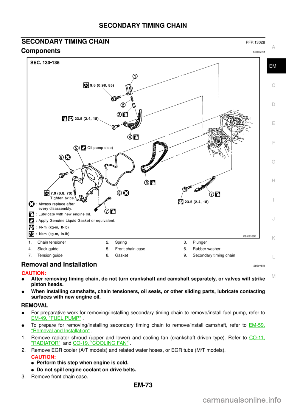
ComponentsEBS01EKA
Removal and InstallationEBS01E68
CAUTION:
lAfter removing timing chain, do not turn crankshaft and camshaft separately, or valves will strike
piston heads.
lWhen installing camshafts, chain tensioners, oil seals, or other sliding parts, lubricate contacting
surfaces with new engine oil.
REMOVAL
lFor preparative work for removing/installing secondary timing chain to remove/install fuel pump, refer to
EM-49, "
FUEL PUMP".
lTo prepare for removing/installing secondary timing chain to remove/install camshaft, refer toEM-59,
"Removal and Installation".
1. Remove radiator shroud (upper and lower) and cooling fan (crankshaft driven type). Refer toCO-11,
"RADIATOR"andCO-19, "COOLING FAN".
2. Remove EGR cooler (A/T models) and related water hoses, or EGR tube (M/T models).
CAUTION:
lPerform this step when engine is cold.
lDo not spill engine coolant on drive belts.
3. Remove front chain case.
1. Chain tensioner 2. Spring 3. Plunger
4. Slack guide 5. Front chain case 6. Rubber washer
7. Tension guide 8. Gasket 9. Secondary timing chain
PBIC2326E
Page 1469 of 3171

PRIMARY TIMING CHAIN
EM-87
C
D
E
F
G
H
I
J
K
L
MA
EM
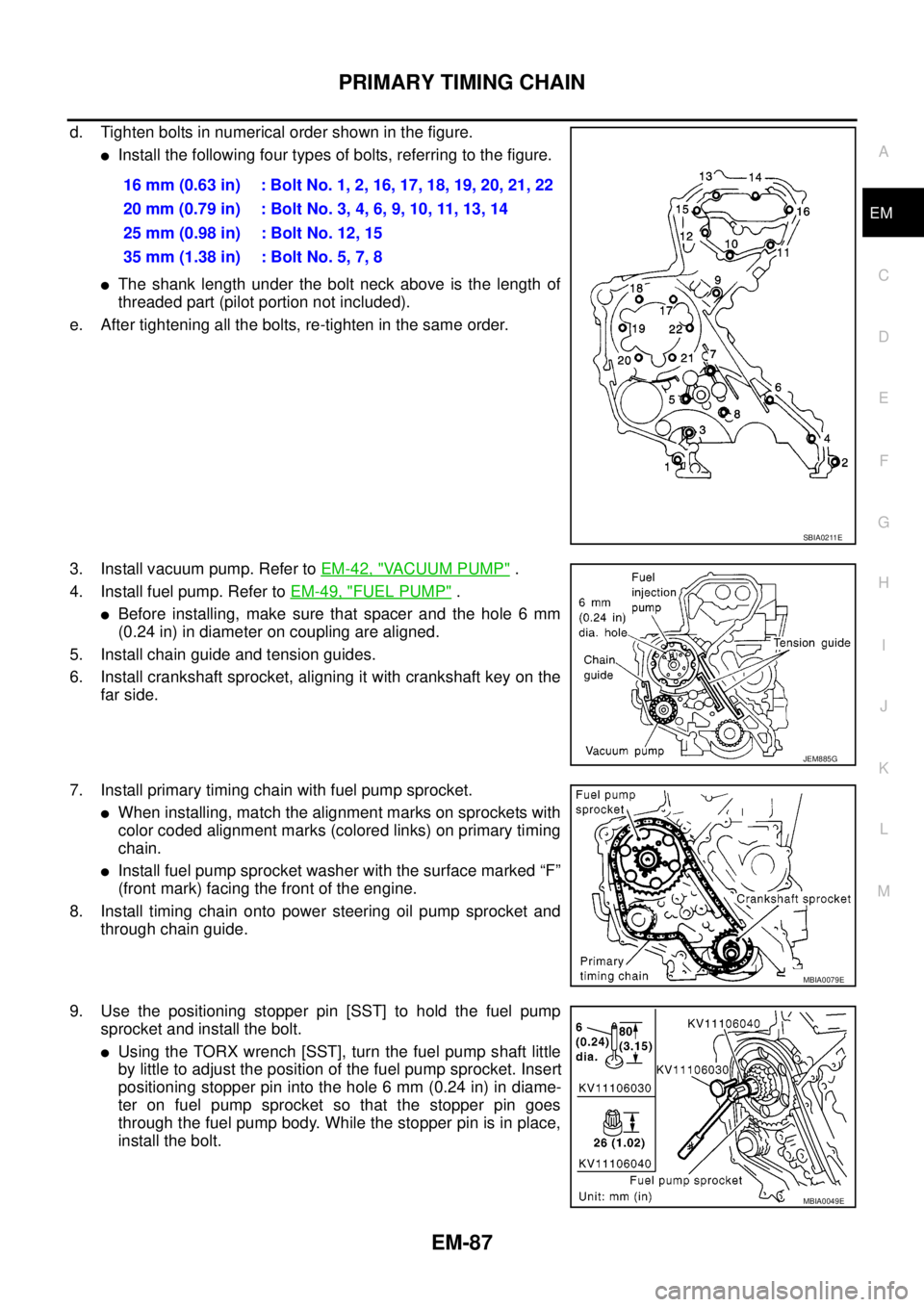
d. Tighten bolts in numerical order shown in the figure.
lInstall the following four types of bolts, referring to the figure.
lThe shank length under the bolt neck above is the length of
threaded part (pilot portion not included).
e. After tightening all the bolts, re-tighten in the same order.
3. Install vacuum pump. Refer toEM-42, "
VACUUM PUMP".
4. Install fuel pump. Refer toEM-49, "
FUEL PUMP".
lBefore installing, make sure that spacer and the hole 6 mm
(0.24 in) in diameter on coupling are aligned.
5. Install chain guide and tension guides.
6. Install crankshaft sprocket, aligning it with crankshaft key on the
far side.
7. Install primary timing chain with fuel pump sprocket.
lWhen installing, match the alignment marks on sprockets with
color coded alignment marks (colored links) on primary timing
chain.
lInstall fuel pump sprocket washer with the surface marked “F”
(front mark) facing the front of the engine.
8. Install timing chain onto power steering oil pump sprocket and
through chain guide.
9. Use the positioning stopper pin [SST] to hold the fuel pump
sprocket and install the bolt.
lUsing the TORX wrench [SST], turn the fuel pump shaft little
by little to adjust the position of the fuel pump sprocket. Insert
positioning stopper pin into the hole 6 mm (0.24 in) in diame-
ter on fuel pump sprocket so that the stopper pin goes
through the fuel pump body. While the stopper pin is in place,
install the bolt.16 mm (0.63 in) : Bolt No. 1, 2, 16, 17, 18, 19, 20, 21, 22
20mm(0.79in) :BoltNo.3,4,6,9,10,11,13,14
25 mm (0.98 in) : Bolt No. 12, 15
35 mm (1.38 in) : Bolt No. 5, 7, 8
SBIA0211E
JEM885G
MBIA0079E
MBIA0049E
Page 1589 of 3171

FUEL FILTER
FL-5
C
D
E
F
G
H
I
J
K
L
MA
FL
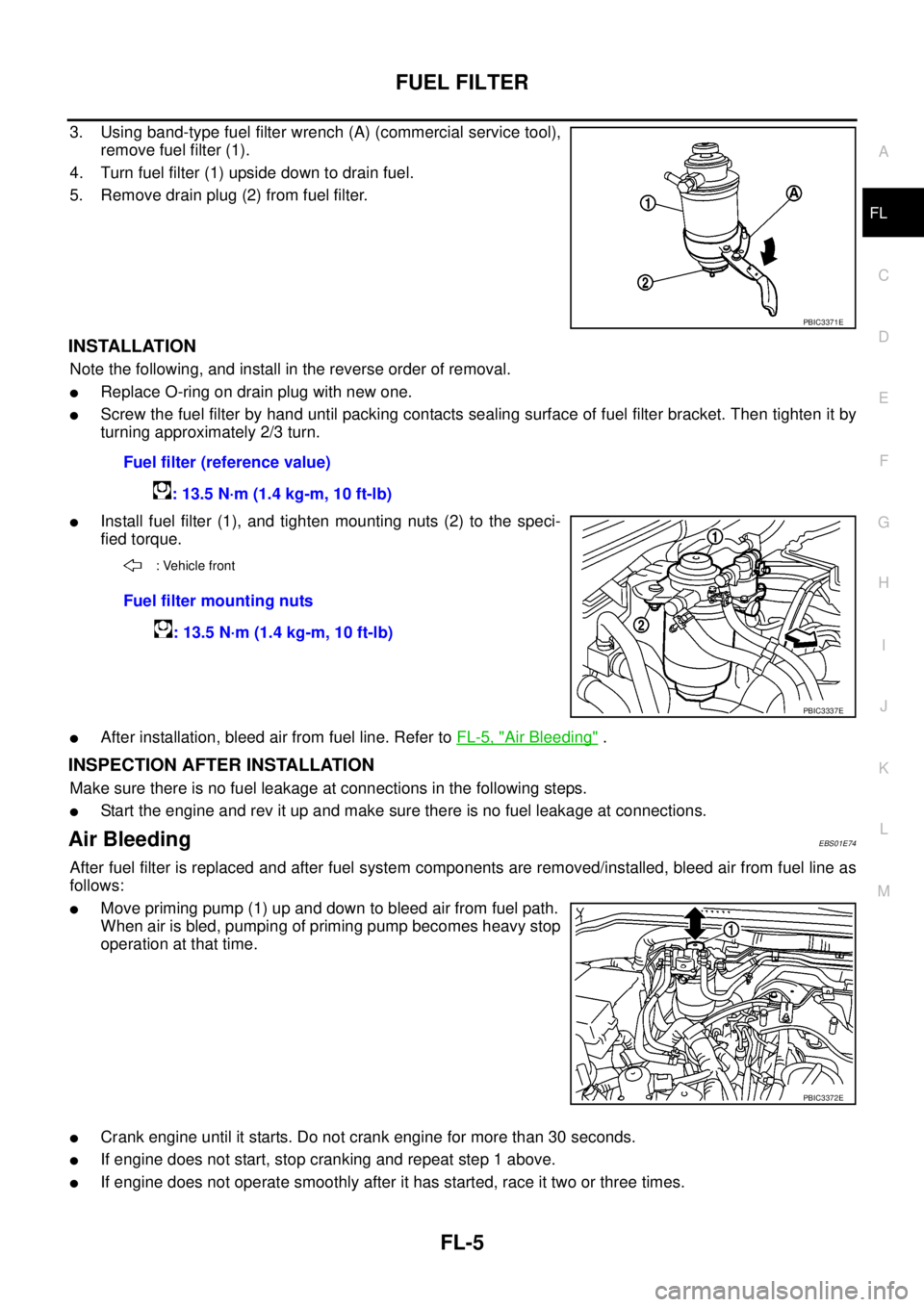
3. Using band-type fuel filter wrench (A) (commercial service tool),
remove fuel filter (1).
4. Turn fuel filter (1) upside down to drain fuel.
5. Remove drain plug (2) from fuel filter.
INSTALLATION
Note the following, and install in the reverse order of removal.
lReplace O-ring on drain plug with new one.
lScrew the fuel filter by hand until packing contacts sealing surface of fuel filter bracket. Then tighten it by
turning approximately 2/3 turn.
lInstall fuel filter (1), and tighten mounting nuts (2) to the speci-
fied torque.
lAfter installation, bleed air from fuel line. Refer toFL-5, "Air Bleeding".
INSPECTION AFTER INSTALLATION
Make sure there is no fuel leakage at connections in the following steps.
lStart the engine and rev it up and make sure there is no fuel leakage at connections.
Air BleedingEBS01E74
After fuel filter is replaced and after fuel system components are removed/installed, bleed air from fuel line as
follows:
lMove priming pump (1) up and down to bleed air from fuel path.
When air is bled, pumping of priming pump becomes heavy stop
operation at that time.
lCrank engine until it starts. Do not crank engine for more than 30 seconds.
lIf engine does not start, stop cranking and repeat step 1 above.
lIf engine does not operate smoothly after it has started, race it two or three times.
PBIC3371E
Fuel filter (reference value)
: 13.5 N·m (1.4 kg-m, 10 ft-lb)
: Vehicle front
Fuel filter mounting nuts
: 13.5 N·m (1.4 kg-m, 10 ft-lb)
PBIC3337E
PBIC3372E