Page 2809 of 3171
RSU-4
REAR SUSPENSION ASSEMBLY
REAR SUSPENSION ASSEMBLY
PFP:55020
ComponentsEES002JG
1. Rear final drive 2. Rear leaf spring 3. Rear spring bushing (front)
4. Rear spring pad 5. Rear spring bushing (rear) 6. Rear spring shackle
7. Bumper 8. Rear spring clip U-bolts 9. Rear spring shackle bushing
MEIB9017E
Page 2810 of 3171
REAR SUSPENSION ASSEMBLY
RSU-5
C
D
F
G
H
I
J
K
L
MA
B
RSU
CAUTION:
When installing the components with rubber bushings, the final tightening of the nuts and bolts must
be done with the vehicle in an unladen condition (the fuel, engine coolant, and engine oil full; the
spare tire, jack, hand tools and mats in their designated positions) with the tires on the ground.
On-Vehicle Inspection and ServiceEES002JH
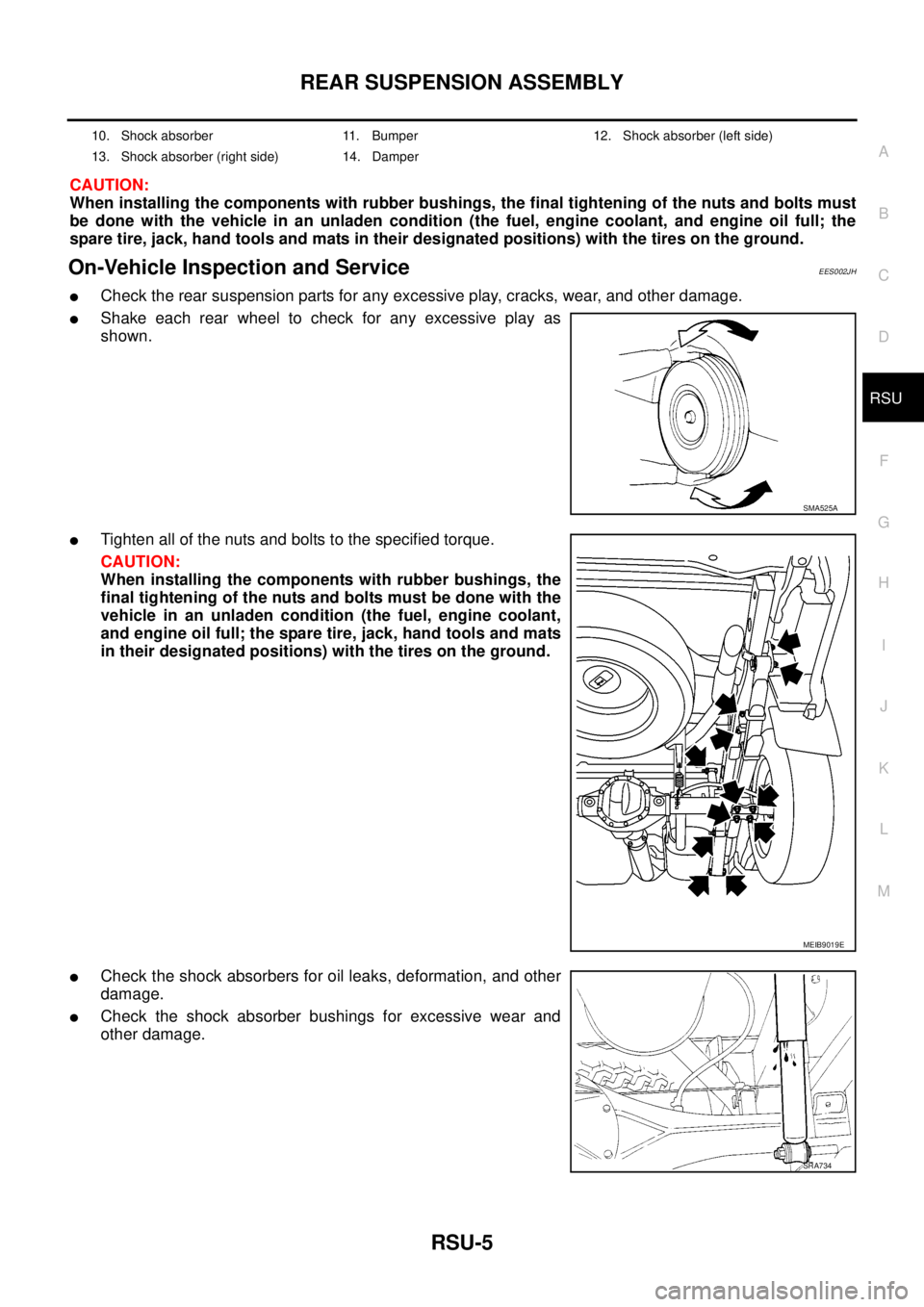
lCheck the rear suspension parts for any excessive play, cracks, wear, and other damage.
lShake each rear wheel to check for any excessive play as
shown.
lTighten all of the nuts and bolts to the specified torque.
CAUTION:
When installing the components with rubber bushings, the
final tightening of the nuts and bolts must be done with the
vehicle in an unladen condition (the fuel, engine coolant,
and engine oil full; the spare tire, jack, hand tools and mats
in their designated positions) with the tires on the ground.
lCheck the shock absorbers for oil leaks, deformation, and other
damage.
lCheck the shock absorber bushings for excessive wear and
other damage.
10. Shock absorber 11. Bumper 12. Shock absorber (left side)
13. Shock absorber (right side) 14. Damper
SMA525A
MEIB9019E
SRA734
Page 2811 of 3171
RSU-6
SHOCK ABSORBER
SHOCK ABSORBER
PFP:56210
Removal and InstallationEES002JI
REMOVAL
1. Support the rear final drive and suspension assembly using a suitable jack.
2. Remove the shock absorber upper and lower nuts and bolts.
3. Remove the shock absorber.
INSPECTION AFTER REMOVAL
lInspect the shock absorber for any oil leaks, cracks, or deformations. Replace the shock absorber as nec-
essary.
lCheck the shock absorber for smooth operation through a full stroke, both compression and extension.
lIf rubber bushings are cracked or deformed, replace rubber bushings.
INSTALLATION
Installation is in the reverse order of removal.
LEIA0115E
Shock absorber upper and lower nuts : Refer toRSU-4, "Components".
Page 2814 of 3171
LEAF SPRING
RSU-9
C
D
F
G
H
I
J
K
L
MA
B
RSU
INSPECTION AFTER REMOVAL
lCheck the rear leaf spring for any cracks or damage. Replace the rear leaf spring if necessary.
lCheck the rear spring shackle, rear spring clip U-bolts, bumper, and rear spring pad for excessive wear,
cracks, straightness, and damage. Replace any components if necessary.
lCheck all bushings for deformation and cracks. Replace any bushings if necessary.
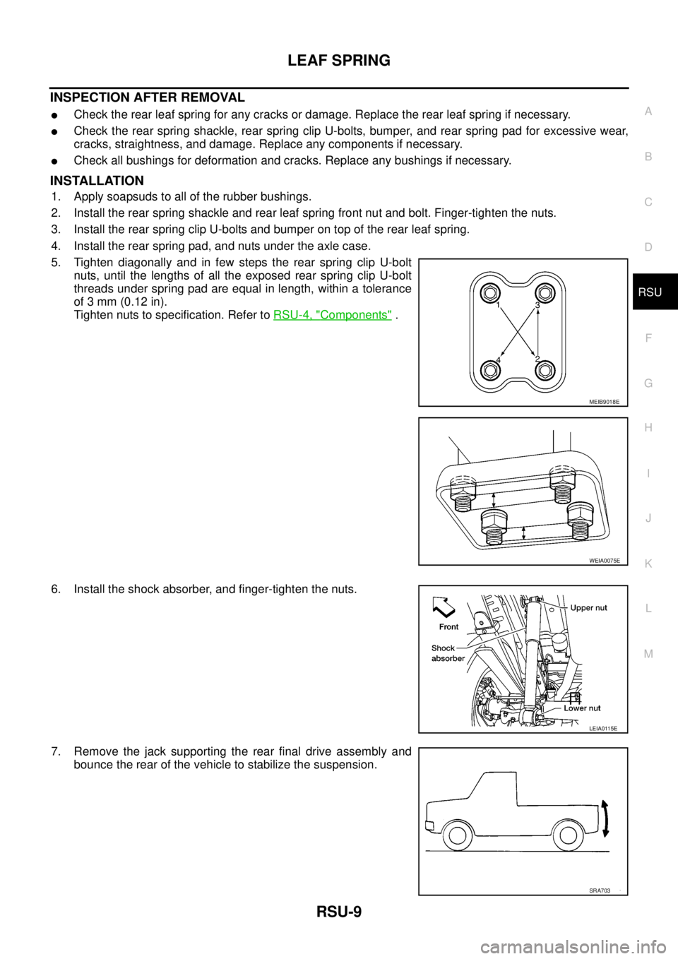
INSTALLATION
1. Apply soapsuds to all of the rubber bushings.
2. Install the rear spring shackle and rear leaf spring front nut and bolt. Finger-tighten the nuts.
3. Install the rear spring clip U-bolts and bumper on top of the rear leaf spring.
4. Install the rear spring pad, and nuts under the axle case.
5. Tighten diagonally and in few steps the rear spring clip U-bolt
nuts, until the lengths of all the exposed rear spring clip U-bolt
threads under spring pad are equal in length, within a tolerance
of 3 mm (0.12 in).
Tighten nuts to specification. Refer toRSU-4, "
Components".
6. Install the shock absorber, and finger-tighten the nuts.
7. Remove the jack supporting the rear final drive assembly and
bounce the rear of the vehicle to stabilize the suspension.
MEIB9018E
WEIA0075E
LEIA0115E
SRA703
Page 2816 of 3171
SERVICE DATA AND SPECIFICATIONS (SDS)
RSU-11
C
D
F
G
H
I
J
K
L
MA
B
RSU
SERVICE DATA AND SPECIFICATIONS (SDS)PFP:00030
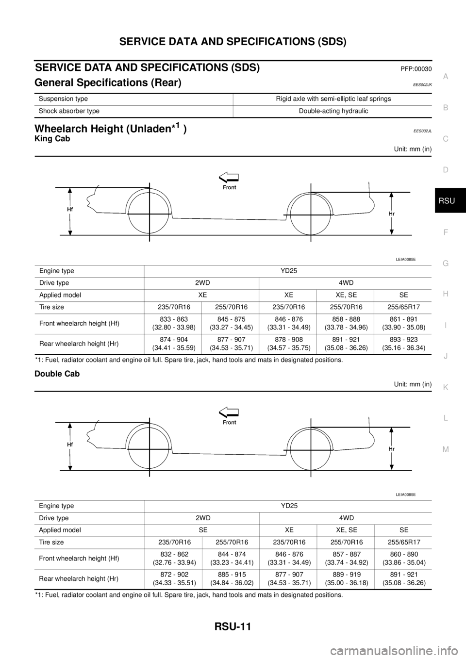
General Specifications (Rear)EES002JK
Wheelarch Height (Unladen*1)EES002JL
King Cab
Unit: mm (in)
*1: Fuel, radiator coolant and engine oil full. Spare tire, jack, hand tools and mats in designated positions.
Double Cab
Unit: mm (in)
*1: Fuel, radiator coolant and engine oil full. Spare tire, jack, hand tools and mats in designated positions.Suspension type Rigid axle with semi-elliptic leaf springs
Shock absorber type Double-acting hydraulic
Engine type YD25
Drive type 2WD 4WD
Applied model XE XE XE, SE SE
Tire size 235/70R16 255/70R16 235/70R16 255/70R16 255/65R17
Front wheelarch height (Hf)833 - 863
(32.80 - 33.98)845 - 875
(33.27 - 34.45)846 - 876
(33.31 - 34.49)858 - 888
(33.78 - 34.96)861 - 891
(33.90 - 35.08)
Rear wheelarch height (Hr)874 - 904
(34.41 - 35.59)877 - 907
(34.53 - 35.71)878 - 908
(34.57 - 35.75)891 - 921
(35.08 - 36.26)893 - 923
(35.16 - 36.34)
LEIA0085E
Engine type YD25
Drive type 2WD 4WD
Applied model SE XE XE, SE SE
Tire size 235/70R16 255/70R16 235/70R16 255/70R16 255/65R17
Front wheelarch height (Hf)832 - 862
(32.76 - 33.94)844 - 874
(33.23 - 34.41)846 - 876
(33.31 - 34.49)857 - 887
(33.74 - 34.92)860 - 890
(33.86 - 35.04)
Rear wheelarch height (Hr)872 - 902
(34.33 - 35.51)885 - 915
(34.84 - 36.02)877 - 907
(34.53 - 35.71)889 - 919
(35.00 - 36.18)891 - 921
(35.08 - 36.26)
LEIA0085E
Page 3106 of 3171
WT-1
ROAD WHEELS & TIRES
E SUSPENSION
CONTENTS
C
D
F
G
H
I
J
K
L
M
SECTIONWT
A
B
WT
ROAD WHEELS & TIRES
NOISE, VIBRATION, AND HARSHNESS (NVH)
TROUBLESHOOTING ................................................ 2
NVH Troubleshooting Chart ..................................... 2
WHEEL ....................................................................... 3
Inspection ................................................................. 3
STEEL WHEEL ..................................................... 3
WHEEL AND TIRE ASSEMBLY ................................. 4Balancing Wheels ..................................................... 4
REMOVAL ............................................................. 4
WHEEL BALANCE ADJUSTMENT ....................... 4
Rotation .................................................................... 5
SERVICE DATA AND SPECIFICATIONS (SDS) ........ 6
Road Wheel .............................................................. 6
Tire ........................................................................... 6
Page 3107 of 3171
WT-2
NOISE, VIBRATION, AND HARSHNESS (NVH) TROUBLESHOOTING
NOISE, VIBRATION, AND HARSHNESS (NVH) TROUBLESHOOTING
PFP:00003
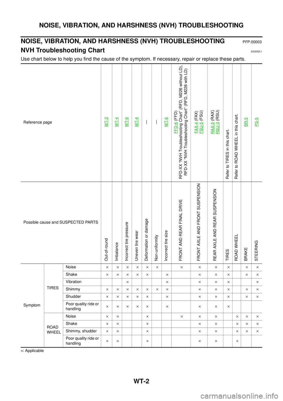
NVH Troubleshooting ChartEES002L1
Use chart below to help you find the cause of the symptom. If necessary, repair or replace these parts.
´: ApplicableReference page
WT-3WT-4WT-6WT-4—
—
WT-6
FFD-6
(FFD)
RFD-XX “NVH Troubleshooting Chart” (RFD, M226 without LD),
RFD-XX “NVH Troubleshooting Chart” (RFD, M226 with LD)
FAX-4(FAX)
FSU-5(FSU)
RAX-5(RAX)
RSU-3(RSU)
Refer to TIRES in this chart.
Refer to ROAD WHEEL in this chart.
BR-5
PS-5
Possible cause and SUSPECTED PARTS
Out-of-round
Imbalance
Incorrect tire pressure
Uneven tire wear
Deformation or damage
Non-uniformity
Incorrect tire size
FRONT AND REAR FINAL DRIVE
FRONT AXLE AND FRONT SUSPENSION
REAR AXLE AND REAR SUSPENSION
TIRES
ROAD WHEEL
BRAKE
STEERING
SymptomTIRESNoise´ ´´´´´ ´ ´ ´ ´ ´ ´
Shake´´´´´ ´ ´ ´ ´ ´´
Vibration´´´´´´
Shimmy´ ´´´´´´ ´ ´ ´ ´ ´
Shudder´´´´´ ´ ´ ´ ´ ´´
Poor quality ride or
handling´´´´´ ´ ´ ´ ´
ROAD
WHEELNoise´´ ´ ´ ´ ´ ´´´
Shake´´ ´ ´ ´ ´´´
Shimmy, shudder´´ ´ ´ ´ ´´´
Poor quality ride or
handling´´ ´ ´ ´ ´
Page 3108 of 3171
WHEEL
WT-3
C
D
F
G
H
I
J
K
L
MA
B
WT
WHEELPFP:40300
InspectionEES002L2
1. Check tires for wear and improper inflation.
2. Check wheels for deformation, cracks and other damage. If
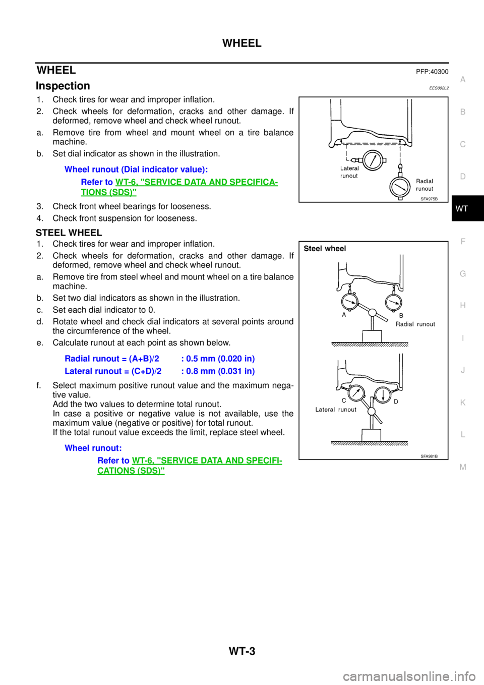
deformed, remove wheel and check wheel runout.
a. Remove tire from wheel and mount wheel on a tire balance
machine.
b. Set dial indicator as shown in the illustration.
3. Check front wheel bearings for looseness.
4. Check front suspension for looseness.
STEEL WHEEL
1. Check tires for wear and improper inflation.
2. Check wheels for deformation, cracks and other damage. If
deformed, remove wheel and check wheel runout.
a. Remove tire from steel wheel and mount wheel on a tire balance
machine.
b. Set two dial indicators as shown in the illustration.
c. Set each dial indicator to 0.
d. Rotate wheel and check dial indicators at several points around
the circumference of the wheel.
e. Calculate runout at each point as shown below.
f. Select maximum positive runout value and the maximum nega-
tive value.
Add the two values to determine total runout.
In case a positive or negative value is not available, use the
maximum value (negative or positive) for total runout.
If the total runout value exceeds the limit, replace steel wheel.Wheel runout (Dial indicator value):
Refer toWT-6, "
SERVICE DATA AND SPECIFICA-
TIONS (SDS)"SFA975B
Radial runout = (A+B)/2 : 0.5 mm (0.020 in)
Lateral runout = (C+D)/2 : 0.8 mm (0.031 in)
Wheel runout:
Refer toWT-6, "
SERVICE DATA AND SPECIFI-
CATIONS (SDS)"
SFA981B