2005 NISSAN NAVARA fuel injector
[x] Cancel search: fuel injectorPage 908 of 3171
CO-24
THERMOSTAT AND WATER PIPING
Removal and Installation
EBS01E6X
WARNING:
Do not remove radiator cap and/or reservoir tank cap when engine is hot. Serious burns could occur
from high pressure engine coolant escaping from radiator and/or reservoir tank.
REMOVAL
1. Remove front engine undercover and middle engine undercover. Refer toEI-15, "FRONT BUMPER".
2. Drain engine coolant from radiator drain plug at the bottom of radiator, and from water drain plug at the
side of cylinder block. Refer toCO-7, "
Changing Engine Coolant"andEM-110, "CYLINDER BLOCK".
CAUTION:
Perform this step when engine is cold.
3. Remove engine cover. Refer toEM-20, "
INTAKE MANIFOLD".
4. Disconnect radiator hoses (upper and lower) from engine side. Refer toCO-11, "
RADIATOR".
5. Remove air inlet pipe and air duct between air cleaner case and turbocharger. Refer toEM-15, "
AIR
CLEANER AND AIR DUCT"andEM-28, "TURBO CHARGER".
6. Remove water outlet, water inlet and thermostat.
7. Remove thermostat housing.
8. Disconnect heater return hose and water hoses at heater return pipe side, and remove heater return pipe.
9. Remove oil level gauge guide mounting bolt, vacuum hoses (to turbocharger boost control solenoid valve)
and spill hose. Refer toEM-36, "
OIL PAN AND OIL STRAINER",EM-20, "INTAKE MANIFOLD"andEM-
44, "INJECTION TUBE AND FUEL INJECTOR".
10. Disconnect water hoses (to EGR cooler) (A/T models), vacuum hoses and heater feed hose at heater
feed pipe side, and remove heater feed pipe. Refer toEM-20, "
INTAKE MANIFOLD".
INSPECTION AFTER REMOVAL
Thermostat
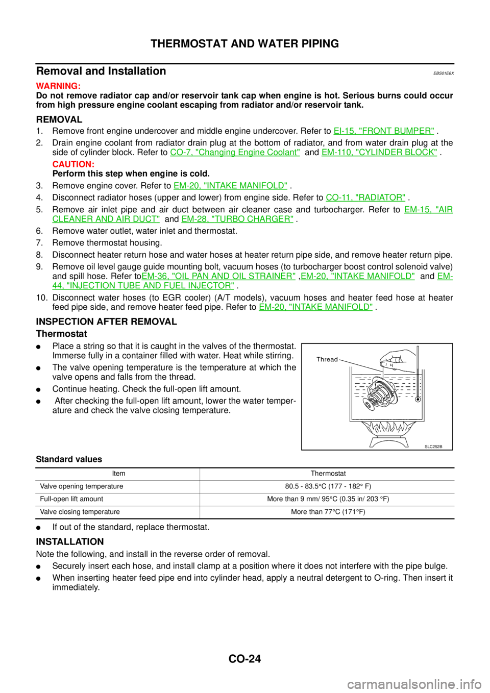
lPlace a string so that it is caught in the valves of the thermostat.
Immerse fully in a container filled with water. Heat while stirring.
lThe valve opening temperature is the temperature at which the
valve opens and falls from the thread.
lContinue heating. Check the full-open lift amount.
lAfter checking the full-open lift amount, lower the water temper-
ature and check the valve closing temperature.
Standard values
lIf out of the standard, replace thermostat.
INSTALLATION
Note the following, and install in the reverse order of removal.
lSecurely insert each hose, and install clamp at a position where it does not interfere with the pipe bulge.
lWhen inserting heater feed pipe end into cylinder head, apply a neutral detergent to O-ring. Then insert it
immediately.
SLC252B
Item Thermostat
Valve opening temperature 80.5 - 83.5°C (177 - 182°F)
Full-open lift amount More than 9 mm/ 95°C (0.35 in/ 203°F)
Valve closing temperature More than 77°C(171°F)
Page 981 of 3171
EC-1
ENGINE CONTROL SYSTEM
B ENGINE
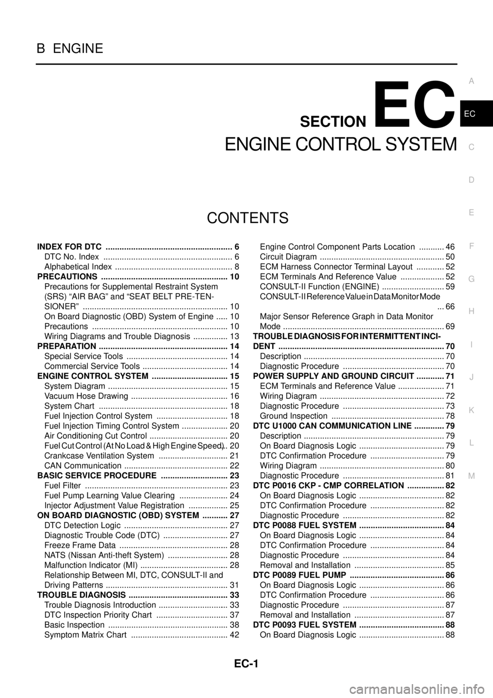
CONTENTS
C
D
E
F
G
H
I
J
K
L
M
SECTIONEC
A
EC
ENGINE CONTROL SYSTEM
INDEX FOR DTC ........................................................ 6
DTC No. Index ......................................................... 6
Alphabetical Index .................................................... 8
PRECAUTIONS ........................................................ 10
Precautions for Supplemental Restraint System
(SRS)“AIRBAG”and“SEATBELTPRE-TEN-
SIONER” ................................................................ 10
On Board Diagnostic (OBD) System of Engine ...... 10
Precautions ............................................................ 10
Wiring Diagrams and Trouble Diagnosis ................ 13
PREPARATION ......................................................... 14
Special Service Tools ............................................. 14
Commercial Service Tools ...................................... 14
ENGINE CONTROL SYSTEM .................................. 15
System Diagram ..................................................... 15
Vacuum Hose Drawing ........................................... 16
System Chart ......................................................... 18
Fuel Injection Control System ................................ 18
Fuel Injection Timing Control System ..................... 20
Air Conditioning Cut Control ................................... 20
Fuel Cut Control (At No Load & High Engine Speed)... 20
Crankcase Ventilation System ............................... 21
CAN Communication .............................................. 22
BASIC SERVICE PROCEDURE .............................. 23
Fuel Filter ............................................................... 23
Fuel Pump Learning Value Clearing ...................... 24
Injector Adjustment Value Registration .................. 25
ON BOARD DIAGNOSTIC (OBD) SYSTEM ............ 27
DTC Detection Logic .............................................. 27
Diagnostic Trouble Code (DTC) ............................. 27
Freeze Frame Data ................................................ 28
NATS (Nissan Anti-theft System) ........................... 28
Malfunction Indicator (MI) ....................................... 28
Relationship Between MI, DTC, CONSULT-II and
Driving Patterns ...................................................... 31
TROUBLE DIAGNOSIS ............................................ 33
Trouble Diagnosis Introduction ............................... 33
DTC Inspection Priority Chart ................................ 37
Basic Inspection ..................................................... 38
Symptom Matrix Chart ........................................... 42Engine Control Component Parts Location ............ 46
Circuit Diagram ....................................................... 50
ECM Harness Connector Terminal Layout ............. 52
ECM Terminals And Reference Value .................... 52
CONSULT-II Function (ENGINE) ............................ 59
CONSULT-II Reference Value in Data Monitor Mode
... 66
Major Sensor Reference Graph in Data Monitor
Mode ....................................................................... 69
TROUBLE DIAGNOSIS FOR INTERMITTENT INCI-
DENT ......................................................................... 70
Description .............................................................. 70
Diagnostic Procedure ............................................. 70
POWER SUPPLY AND GROUND CIRCUIT ............. 71
ECM Terminals and Reference Value ..................... 71
Wiring Diagram ....................................................... 72
Diagnostic Procedure ............................................. 73
Ground Inspection .................................................. 78
DTC U1000 CAN COMMUNICATION LINE .............. 79
Description .............................................................. 79
On Board Diagnosis Logic ...................................... 79
DTC Confirmation Procedure ................................. 79
Wiring Diagram ....................................................... 80
Diagnostic Procedure ............................................. 81
DTC P0016 CKP - CMP CORRELATION ................. 82
On Board Diagnosis Logic ...................................... 82
DTC Confirmation Procedure ................................. 82
Diagnostic Procedure ............................................. 82
DTC P0088 FUEL SYSTEM ...................................... 84
On Board Diagnosis Logic ...................................... 84
DTC Confirmation Procedure ................................. 84
Diagnostic Procedure ............................................. 84
Removal and Installation ........................................ 85
DTC P0089 FUEL PUMP .......................................... 86
On Board Diagnosis Logic ...................................... 86
DTC Confirmation Procedure ................................. 86
Diagnostic Procedure ............................................. 87
Removal and Installation ........................................ 87
DTC P0093 FUEL SYSTEM ...................................... 88
On Board Diagnosis Logic ...................................... 88
Page 982 of 3171

EC-2
DTC Confirmation Procedure ................................. 88
Diagnostic Procedure ............................................. 89
Component Inspection ............................................ 90
Removal and Installation ........................................ 91
DTC P0102, P0103 MAF SENSOR ........................... 92
Component Description .......................................... 92
CONSULT-II Reference Value in Data Monitor Mode
... 92
ECM Terminals and Reference Value ..................... 92
On Board Diagnosis Logic ...................................... 93
DTC Confirmation Procedure ................................. 93
Wiring Diagram ....................................................... 94
Diagnostic Procedure ............................................. 95
Component Inspection ............................................ 96
Removal and Installation ........................................ 97
DTC P0112, P0113 IAT SENSOR ............................. 98
Component Description .......................................... 98
On Board Diagnosis Logic ...................................... 98
DTC Confirmation Procedure ................................. 98
Wiring Diagram .....................................................100
Diagnostic Procedure ...........................................101
Component Inspection ..........................................102
Removal and Installation ......................................102
DTC P0117, P0118 ECT SENSOR ..........................103
Description ............................................................103
On Board Diagnosis Logic ....................................103
DTC Confirmation Procedure ...............................103
Wiring Diagram .....................................................105
Diagnostic Procedure ...........................................106
Component Inspection ..........................................107
Removal and Installation ......................................107
DTC P0122, P0123 APP SENSOR .........................108
Description ............................................................108
CONSULT-II Reference Value in Data Monitor Mode
.108
ECM Terminals and Reference Value ...................108
On Board Diagnosis Logic ....................................109
DTC Confirmation Procedure ...............................109
Wiring Diagram .....................................................110
Diagnostic Procedure ............................................111
Component Inspection ..........................................112
Removal and Installation ......................................112
DTC P0182, P0183 FUEL PUMP TEMPERATURE
SENSOR ..................................................................113
Description ............................................................113
CONSULT-II Reference Value in Data Monitor Mode
.113
ECM Terminals and Reference Value ...................113
On Board Diagnosis Logic ....................................113
DTC Confirmation Procedure ...............................114
Wiring Diagram .....................................................115
Diagnostic Procedure ...........................................116
Removal and Installation ......................................117
DTC P0192, P0193 FRP SENSOR .........................118
Description ............................................................118
CONSULT-II Reference Value in Data Monitor Mode
.118
ECM Terminals and Reference Value ...................118
On Board Diagnosis Logic ....................................118DTC Confirmation Procedure ................................119
Wiring Diagram .....................................................120
Diagnostic Procedure ............................................121
Component Inspection ..........................................122
Removal and Installation .......................................122
DTC P0200 FUEL INJECTOR .................................123
On Board Diagnosis Logic ....................................123
DTC Confirmation Procedure ................................123
Diagnostic Procedure ............................................123
DTC P0201 - P0204 FUEL INJECTOR ...................125
Component Description ........................................125
CONSULT-II Reference Value in Data Monitor Mode
.125
ECM Terminals and Reference Value ...................125
On Board Diagnosis Logic ....................................126
DTC Confirmation Procedure ................................127
Wiring Diagram .....................................................128
Diagnostic Procedure ............................................129
Component Inspection ..........................................130
Removal and Installation .......................................131
DTC P0217 ENGINE OVER TEMPERATURE ........132
Description ............................................................132
CONSULT-II Reference Value in Data Monitor Mode
.133
On Board Diagnosis Logic ....................................133
Overall Function Check .........................................133
Wiring Diagram .....................................................135
Diagnostic Procedure ............................................137
Main 12 Causes of Overheating ...........................140
Component Inspection ..........................................141
DTC P0222, P0223 APP SENSOR .........................142
Description ............................................................142
CONSULT-II Reference Value in Data Monitor Mode
.142
ECM Terminals and Reference Value ...................142
On Board Diagnosis Logic ....................................143
DTC Confirmation Procedure ................................143
Wiring Diagram .....................................................144
Diagnostic Procedure ............................................145
Component Inspection ..........................................146
Removal and Installation .......................................146
DTC P0234 TC SYSTEM .........................................147
Description ............................................................147
ECM Terminals and Reference Value ...................147
On Board Diagnosis Logic ....................................148
Overall Function Check .........................................148
Wiring Diagram .....................................................149
Diagnostic Procedure ............................................150
Component Inspection ..........................................152
Removal and Installation .......................................152
DTC P0237, P0238 TC BOOST SENSOR ..............153
Component Description ........................................153
CONSULT-II Reference Value in Data Monitor Mode
.153
ECM Terminals and Reference Value ...................153
On Board Diagnosis Logic ....................................154
DTC Confirmation Procedure ................................154
Wiring Diagram .....................................................155
Diagnostic Procedure ............................................156
Page 984 of 3171

EC-4
Wiring Diagram .....................................................234
Diagnostic Procedure ...........................................235
DTC P1268 - P1271 FUEL INJECTOR ...................237
Component Description ........................................237
CONSULT-II Reference Value in Data Monitor Mode
.237
ECM Terminals and Reference Value ...................237
On Board Diagnosis Logic ....................................238
DTC Confirmation Procedure ...............................239
Wiring Diagram .....................................................240
Diagnostic Procedure ...........................................241
Component Inspection ..........................................243
Removal and Installation ......................................244
DTC P1272 FUEL PUMP ........................................245
Description ............................................................245
CONSULT-II Reference Value in Data Monitor Mode
.245
ECM Terminals and Reference Value ...................245
On Board Diagnosis Logic ....................................246
DTC Confirmation Procedure ...............................246
Wiring Diagram .....................................................248
Diagnostic Procedure ...........................................249
Component Inspection ..........................................250
Removal and Installation ......................................250
DTC P1273 FUEL PUMP ........................................251
Description ............................................................251
CONSULT-II Reference Value in Data Monitor Mode
.251
ECM Terminals and Reference Value ...................251
On Board Diagnosis Logic ....................................252
DTC Confirmation Procedure ...............................252
Wiring Diagram .....................................................254
Diagnostic Procedure ...........................................255
Component Inspection ..........................................257
Removal and Installation ......................................257
DTC P1274 FUEL PUMP ........................................258
Description ............................................................258
CONSULT-II Reference Value in Data Monitor Mode
.258
ECM Terminals and Reference Value ...................258
On Board Diagnosis Logic ....................................259
DTC Confirmation Procedure ...............................259
Wiring Diagram .....................................................260
Diagnostic Procedure ...........................................261
Component Inspection ..........................................262
Removal and Installation ......................................262
DTC P1275 FUEL PUMP ........................................263
Description ............................................................263
CONSULT-II Reference Value in Data Monitor Mode
.263
ECM Terminals and Reference Value ...................263
On Board Diagnosis Logic ....................................264
DTC Confirmation Procedure ...............................264
Wiring Diagram .....................................................266
Diagnostic Procedure ...........................................267
Component Inspection ..........................................268
Removal and Installation ......................................268
DTC P1616 ECM .....................................................269
Description ............................................................269On Board Diagnosis Logic ....................................269
DTC Confirmation Procedure ................................269
Diagnostic Procedure ............................................270
DTC P1622 INJECTOR ADJUSTMENT VALUE .....271
Description ............................................................271
On Board Diagnosis Logic ....................................271
DTC Confirmation Procedure ................................271
Diagnostic Procedure ............................................272
DTC P1623 INJECTOR ADJUSTMENT VALUE .....273
Description ............................................................273
On Board Diagnosis Logic ....................................273
DTC Confirmation Procedure ................................273
Diagnostic Procedure ............................................274
DTC P2135 APP SENSOR ......................................275
Description ............................................................275
CONSULT-II Reference Value in Data Monitor Mode
.275
ECM Terminals and Reference Value ...................275
On Board Diagnosis Logic ....................................276
DTC Confirmation Procedure ................................276
Wiring Diagram .....................................................277
Diagnostic Procedure ............................................278
Component Inspection ..........................................279
Removal and Installation .......................................280
DTC P2146, P2149 FUEL INJECTOR POWER SUP-
PLY ..........................................................................281
Component Description ........................................281
CONSULT-II Reference Value in Data Monitor Mode
.281
ECM Terminals and Reference Value ...................281
On Board Diagnosis Logic ....................................282
DTC Confirmation Procedure ................................283
Wiring Diagram .....................................................284
Diagnostic Procedure ............................................285
DTC P2147, P2148 FUEL INJECTOR CIRCUIT .....286
Component Description ........................................286
CONSULT-II Reference Value in Data Monitor Mode
.286
ECM Terminals and Reference Value ...................286
On Board Diagnosis Logic ....................................287
DTC Confirmation Procedure ................................288
Wiring Diagram .....................................................289
Diagnostic Procedure ............................................290
Component Inspection ..........................................292
Removal and Installation .......................................292
DTC P2228, P2229 BARO SENSOR ......................293
Description ............................................................293
On Board Diagnosis Logic ....................................293
DTC Confirmation Procedure ................................293
Diagnostic Procedure ............................................294
GLOW CONTROL SYSTEM ...................................295
Description ............................................................295
Wiring Diagram .....................................................296
Diagnostic Procedure ............................................297
Component Inspection ..........................................301
Removal and Installation .......................................301
EGR VOLUME CONTROL SYSTEM ......................302
Description ............................................................302
CONSULT-II Reference Value in Data Monitor Mode
Page 985 of 3171
EC-5
C
D
E
F
G
H
I
J
K
L
M
ECA . 303
ECM Terminals and Reference Value .................. 303
Wiring Diagram .................................................... 304
Diagnostic Procedure ........................................... 305
Component Inspection ......................................... 307
Removal and Installation ...................................... 308
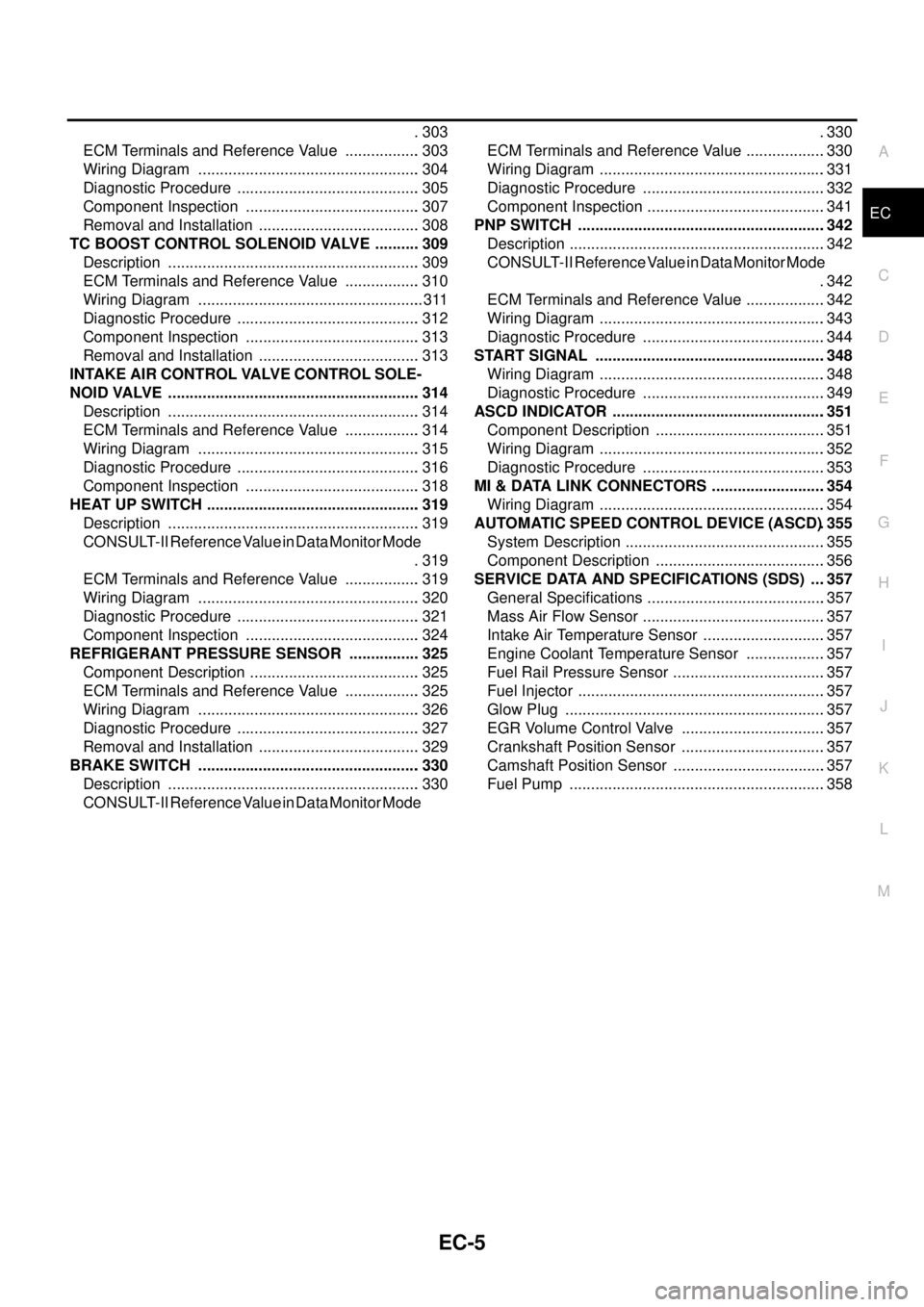
TC BOOST CONTROL SOLENOID VALVE ........... 309
Description ........................................................... 309
ECM Terminals and Reference Value .................. 310
Wiring Diagram ..................................................... 311
Diagnostic Procedure ........................................... 312
Component Inspection ......................................... 313
Removal and Installation ...................................... 313
INTAKE AIR CONTROL VALVE CONTROL SOLE-
NOID VALVE ........................................................... 314
Description ........................................................... 314
ECM Terminals and Reference Value .................. 314
Wiring Diagram .................................................... 315
Diagnostic Procedure ........................................... 316
Component Inspection ......................................... 318
HEAT UP SWITCH .................................................. 319
Description ........................................................... 319
CONSULT-II Reference Value in Data Monitor Mode
. 319
ECM Terminals and Reference Value .................. 319
Wiring Diagram .................................................... 320
Diagnostic Procedure ........................................... 321
Component Inspection ......................................... 324
REFRIGERANT PRESSURE SENSOR ................. 325
Component Description ........................................ 325
ECM Terminals and Reference Value .................. 325
Wiring Diagram .................................................... 326
Diagnostic Procedure ........................................... 327
Removal and Installation ...................................... 329
BRAKE SWITCH .................................................... 330
Description ........................................................... 330
CONSULT-II Reference Value in Data Monitor Mode.330
ECM Terminals and Reference Value ...................330
Wiring Diagram .....................................................331
Diagnostic Procedure ...........................................332
Component Inspection ..........................................341
PNP SWITCH ..........................................................342
Description ............................................................342
CONSULT-II Reference Value in Data Monitor Mode
.342
ECM Terminals and Reference Value ...................342
Wiring Diagram .....................................................343
Diagnostic Procedure ...........................................344
START SIGNAL ......................................................348
Wiring Diagram .....................................................348
Diagnostic Procedure ...........................................349
ASCD INDICATOR ..................................................351
Component Description ........................................351
Wiring Diagram .....................................................352
Diagnostic Procedure ...........................................353
MI & DATA LINK CONNECTORS ...........................354
Wiring Diagram .....................................................354
AUTOMATIC SPEED CONTROL DEVICE (ASCD). 355
System Description ...............................................355
Component Description ........................................356
SERVICE DATA AND SPECIFICATIONS (SDS) ....357
General Specifications ..........................................357
Mass Air Flow Sensor ...........................................357
Intake Air Temperature Sensor .............................357
Engine Coolant Temperature Sensor ...................357
Fuel Rail Pressure Sensor ....................................357
Fuel Injector ..........................................................357
Glow Plug .............................................................357
EGR Volume Control Valve ..................................357
Crankshaft Position Sensor ..................................357
Camshaft Position Sensor ....................................357
Fuel Pump ............................................................358
Page 986 of 3171
EC-6
INDEX FOR DTC
INDEX FOR DTC
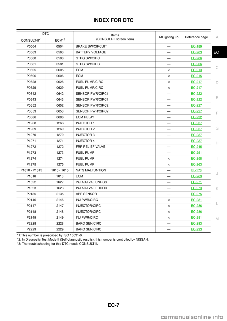
PFP:00024
DTC No. IndexEBS01KC3
NOTE:
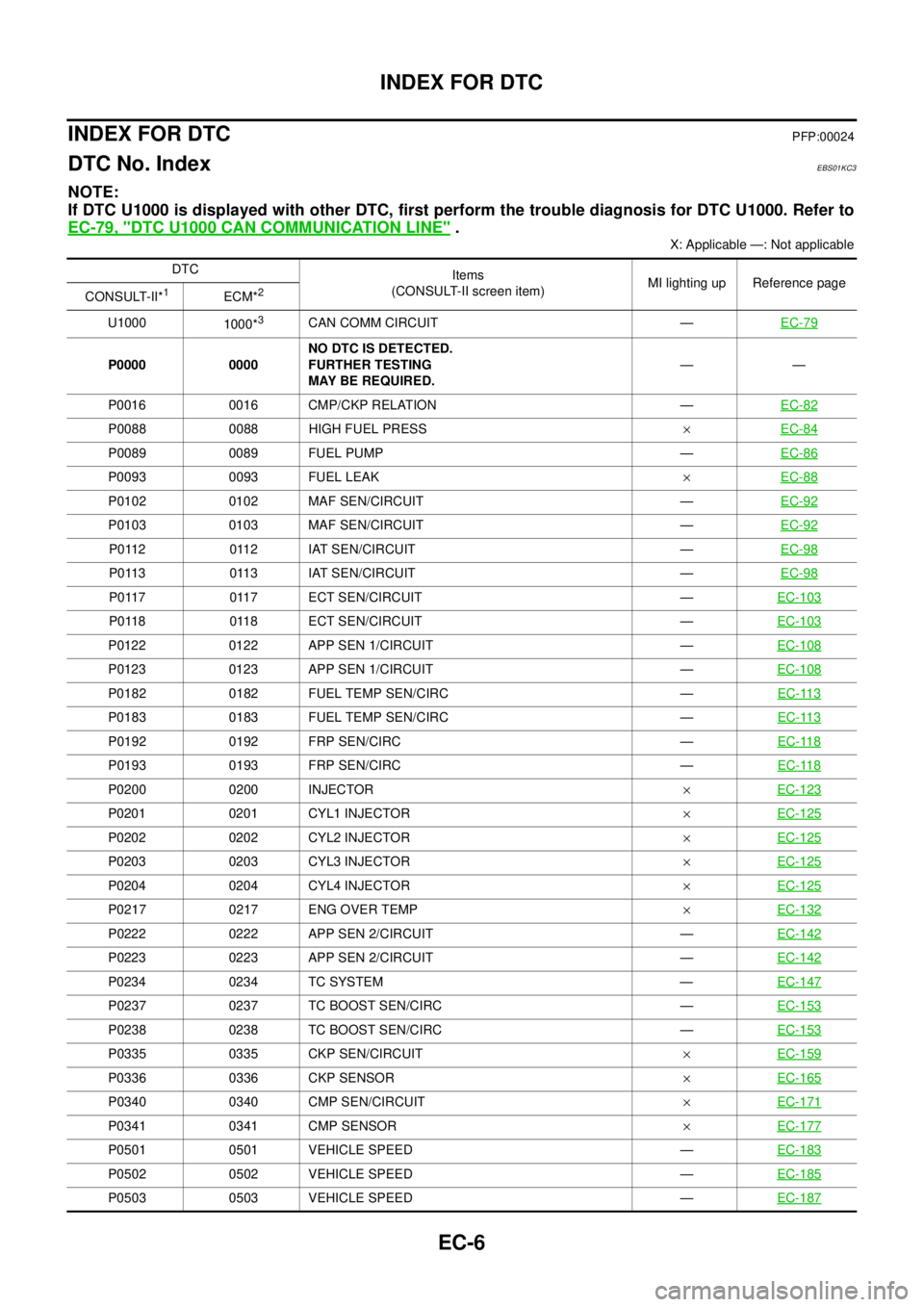
If DTC U1000 is displayed with other DTC, first perform the trouble diagnosis for DTC U1000. Refer to
EC-79, "
DTC U1000 CAN COMMUNICATION LINE".
X: Applicable —: Not applicable
DTC
Items
(CONSULT-II screen item)MI lighting up Reference page
CONSULT-II*
1ECM*2
U1000
1000*3CAN COMM CIRCUIT —EC-79
P0000 0000NO DTC IS DETECTED.
FURTHER TESTING
MAY BE REQUIRED.——
P0016 0016 CMP/CKP RELATION —EC-82
P0088 0088 HIGH FUEL PRESS´EC-84
P0089 0089 FUEL PUMP —EC-86
P0093 0093 FUEL LEAK´EC-88
P0102 0102 MAF SEN/CIRCUIT —EC-92
P0103 0103 MAF SEN/CIRCUIT —EC-92
P0112 0112 IAT SEN/CIRCUIT —EC-98
P0113 0113 IAT SEN/CIRCUIT —EC-98
P0117 0117 ECT SEN/CIRCUIT —EC-103
P0118 0118 ECT SEN/CIRCUIT —EC-103
P0122 0122 APP SEN 1/CIRCUIT —EC-108
P0123 0123 APP SEN 1/CIRCUIT —EC-108
P0182 0182 FUEL TEMP SEN/CIRC —EC-113
P0183 0183 FUEL TEMP SEN/CIRC —EC-113
P0192 0192 FRP SEN/CIRC —EC-118
P0193 0193 FRP SEN/CIRC —EC-118
P0200 0200 INJECTOR´EC-123
P0201 0201 CYL1 INJECTOR´EC-125
P0202 0202 CYL2 INJECTOR´EC-125
P0203 0203 CYL3 INJECTOR´EC-125
P0204 0204 CYL4 INJECTOR´EC-125
P0217 0217 ENG OVER TEMP´EC-132
P0222 0222 APP SEN 2/CIRCUIT —EC-142
P0223 0223 APP SEN 2/CIRCUIT —EC-142
P0234 0234 TC SYSTEM —EC-147
P0237 0237 TC BOOST SEN/CIRC —EC-153
P0238 0238 TC BOOST SEN/CIRC —EC-153
P0335 0335 CKP SEN/CIRCUIT´EC-159
P0336 0336 CKP SENSOR´EC-165
P0340 0340 CMP SEN/CIRCUIT´EC-171
P0341 0341 CMP SENSOR´EC-177
P0501 0501 VEHICLE SPEED —EC-183
P0502 0502 VEHICLE SPEED —EC-185
P0503 0503 VEHICLE SPEED —EC-187
Page 987 of 3171
INDEX FOR DTC
EC-7
C
D
E
F
G
H
I
J
K
L
MA
EC
*1:This number is prescribed by ISO 15031-6.
*2: In Diagnostic Test Mode II (Self-diagnostic results), this number is controlled by NISSAN.
*3: The troubleshooting for this DTC needs CONSULT-II.P0504 0504 BRAKE SW/CIRCUIT —EC-189
P0563 0563 BATTERY VOLTAGE —EC-203
P0580 0580 STRG SW/CIRC —EC-206
P0581 0581 STRG SW/CIRC —EC-206
P0605 0605 ECM´EC-213
P0606 0606 ECM´EC-215
P0628 0628 FUEL PUMP/CIRC´EC-217
P0629 0629 FUEL PUMP/CIRC´EC-217
P0642 0642 SENSOR PWR/CIRC1 —EC-222
P0643 0643 SENSOR PWR/CIRC1 —EC-222
P0652 0652 SENSOR PWR/CIRC2 —EC-227
P0653 0653 SENSOR PWR/CIRC2 —EC-227
P0686 0686 ECM RELAY —EC-232
P1268 1268 INJECTOR 1 —EC-237
P1269 1269 INJECTOR 2 —EC-237
P1270 1270 INJECTOR 3 —EC-237
P1271 1271 INJECTOR 4 —EC-237
P1272 1272 FRP RELIEF VALVE —EC-245
P1273 1273 FUEL PUMP —EC-251
P1274 1274 FUEL PUMP´EC-258
P1275 1275 FUEL PUMP´EC-263
P1610 - P1615 1610 - 1615 NATS MALFUNTION —BL-176
P1616 1616 ECM —EC-269
P1622 1622 INJ ADJ VAL UNRGST —EC-271
P1623 1623 INJ ADJ VAL ERROR —EC-273
P2135 2135 APP SENSOR —EC-275
P2146 2146 INJ PWR/CIRC´EC-281
P2147 2147 INJECTOR/CIRC´EC-286
P2148 2148 INJECTOR/CIRC´EC-286
P2149 2149 INJ PWR/CIRC´EC-281
P2228 2228 BARO SEN/CIRC —EC-293
P2229 2229 BARO SEN/CIRC —EC-293
DTC
Items
(CONSULT-II screen item)MI lighting up Reference page
CONSULT-II*
1ECM*2
Page 988 of 3171
EC-8
INDEX FOR DTC
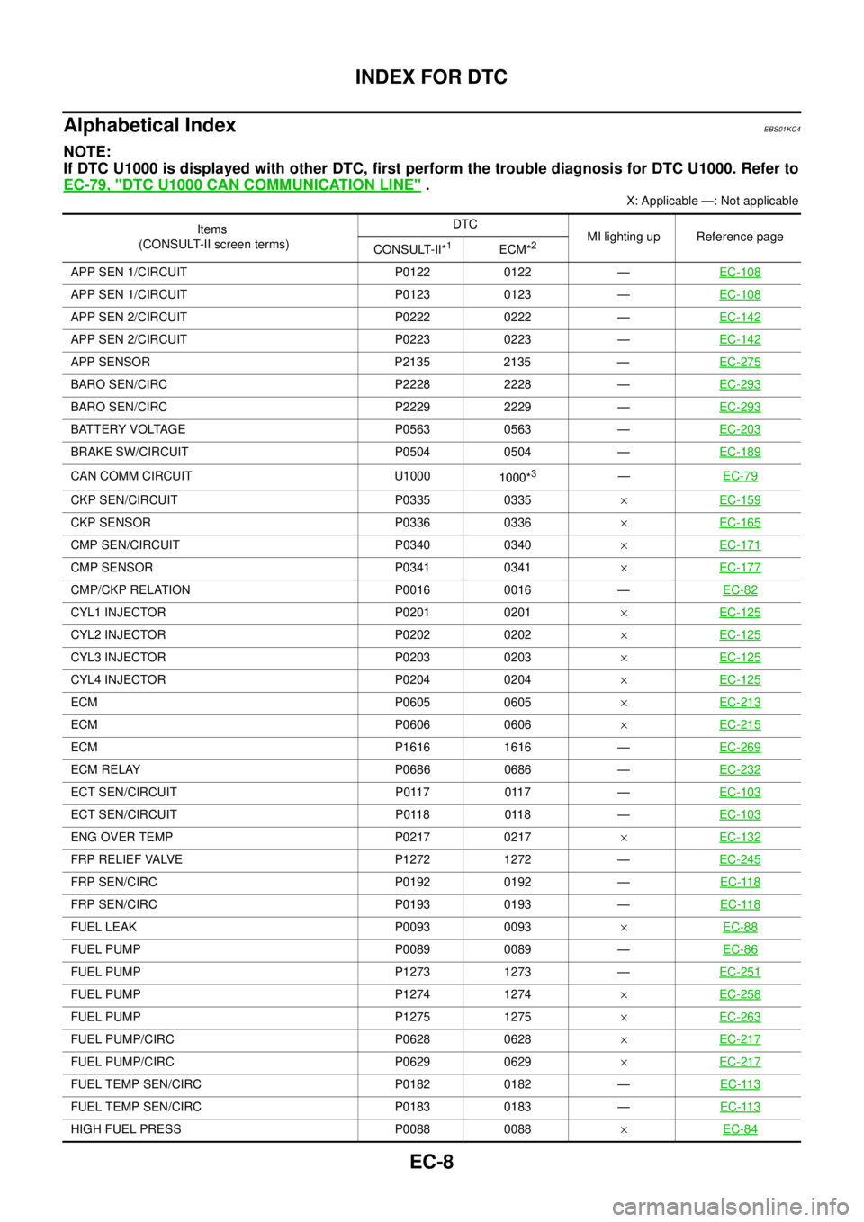
Alphabetical Index
EBS01KC4
NOTE:
If DTC U1000 is displayed with other DTC, first perform the trouble diagnosis for DTC U1000. Refer to
EC-79, "
DTC U1000 CAN COMMUNICATION LINE".
X: Applicable —: Not applicable
Items
(CONSULT-II screen terms)DTC
MI lighting up Reference page
CONSULT-II*
1ECM*2
APP SEN 1/CIRCUIT P0122 0122 —EC-108
APP SEN 1/CIRCUIT P0123 0123 —EC-108
APP SEN 2/CIRCUIT P0222 0222 —EC-142
APP SEN 2/CIRCUIT P0223 0223 —EC-142
APP SENSOR P2135 2135 —EC-275
BARO SEN/CIRC P2228 2228 —EC-293
BARO SEN/CIRC P2229 2229 —EC-293
BATTERY VOLTAGE P0563 0563 —EC-203
BRAKE SW/CIRCUIT P0504 0504 —EC-189
CAN COMM CIRCUIT U1000
1000*3—EC-79
CKP SEN/CIRCUIT P0335 0335´EC-159
CKP SENSOR P0336 0336´EC-165
CMP SEN/CIRCUIT P0340 0340´EC-171
CMP SENSOR P0341 0341´EC-177
CMP/CKP RELATION P0016 0016 —EC-82
CYL1 INJECTOR P0201 0201´EC-125
CYL2 INJECTOR P0202 0202´EC-125
CYL3 INJECTOR P0203 0203´EC-125
CYL4 INJECTOR P0204 0204´EC-125
ECM P0605 0605´EC-213
ECM P0606 0606´EC-215
ECM P1616 1616 —EC-269
ECM RELAY P0686 0686 —EC-232
ECT SEN/CIRCUIT P0117 0117 —EC-103
ECT SEN/CIRCUIT P0118 0118 —EC-103
ENG OVER TEMP P0217 0217´EC-132
FRP RELIEF VALVE P1272 1272 —EC-245
FRP SEN/CIRC P0192 0192 —EC-118
FRP SEN/CIRC P0193 0193 —EC-118
FUEL LEAK P0093 0093´EC-88
FUEL PUMP P0089 0089 —EC-86
FUEL PUMP P1273 1273 —EC-251
FUEL PUMP P1274 1274´EC-258
FUEL PUMP P1275 1275´EC-263
FUEL PUMP/CIRC P0628 0628´EC-217
FUEL PUMP/CIRC P0629 0629´EC-217
FUEL TEMP SEN/CIRC P0182 0182 —EC-113
FUEL TEMP SEN/CIRC P0183 0183 —EC-113
HIGH FUEL PRESS P0088 0088´EC-84