2005 NISSAN NAVARA fuel injector
[x] Cancel search: fuel injectorPage 992 of 3171
EC-12
PRECAUTIONS
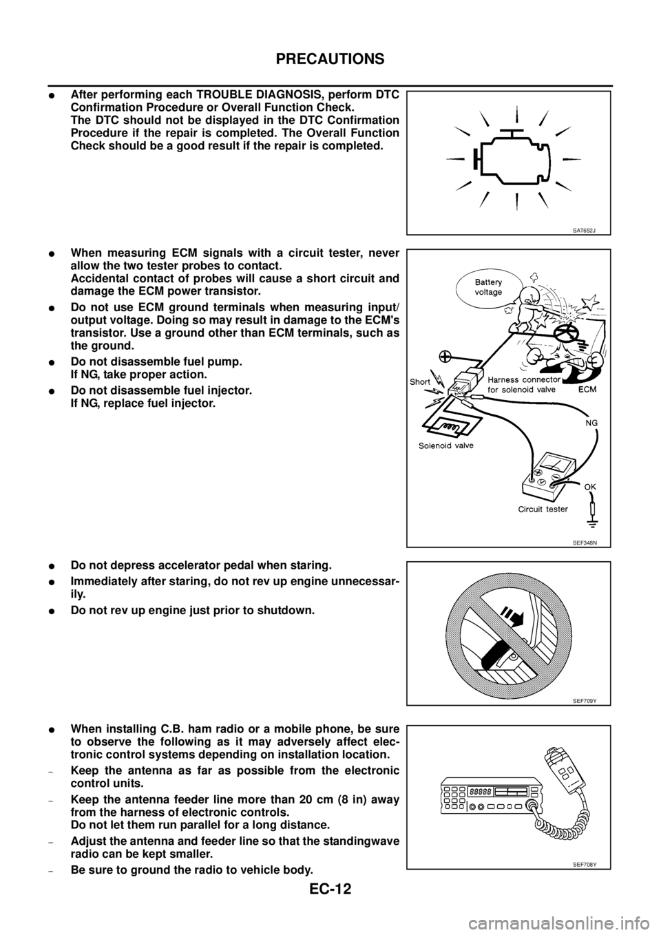
lAfter performing each TROUBLE DIAGNOSIS, perform DTC
Confirmation Procedure or Overall Function Check.
The DTC should not be displayed in the DTC Confirmation
Procedure if the repair is completed. The Overall Function
Check should be a good result if the repair is completed.
lWhen measuring ECM signals with a circuit tester, never
allow the two tester probes to contact.
Accidental contact of probes will cause a short circuit and
damage the ECM power transistor.
lDo not use ECM ground terminals when measuring input/
output voltage. Doing so may result in damage to the ECM's
transistor. Use a ground other than ECM terminals, such as
the ground.
lDo not disassemble fuel pump.
If NG, take proper action.
lDo not disassemble fuel injector.
If NG, replace fuel injector.
lDo not depress accelerator pedal when staring.
lImmediately after staring, do not rev up engine unnecessar-
ily.
lDo not rev up engine just prior to shutdown.
lWhen installing C.B. ham radio or a mobile phone, be sure
to observe the following as it may adversely affect elec-
tronic control systems depending on installation location.
–Keep the antenna as far as possible from the electronic
control units.
–Keep the antenna feeder line more than 20 cm (8 in) away
from the harness of electronic controls.
Do not let them run parallel for a long distance.
–Adjust the antenna and feeder line so that the standingwave
radio can be kept smaller.
–Be sure to ground the radio to vehicle body.
SAT652J
SEF348N
SEF709Y
SEF708Y
Page 998 of 3171
EC-18
ENGINE CONTROL SYSTEM
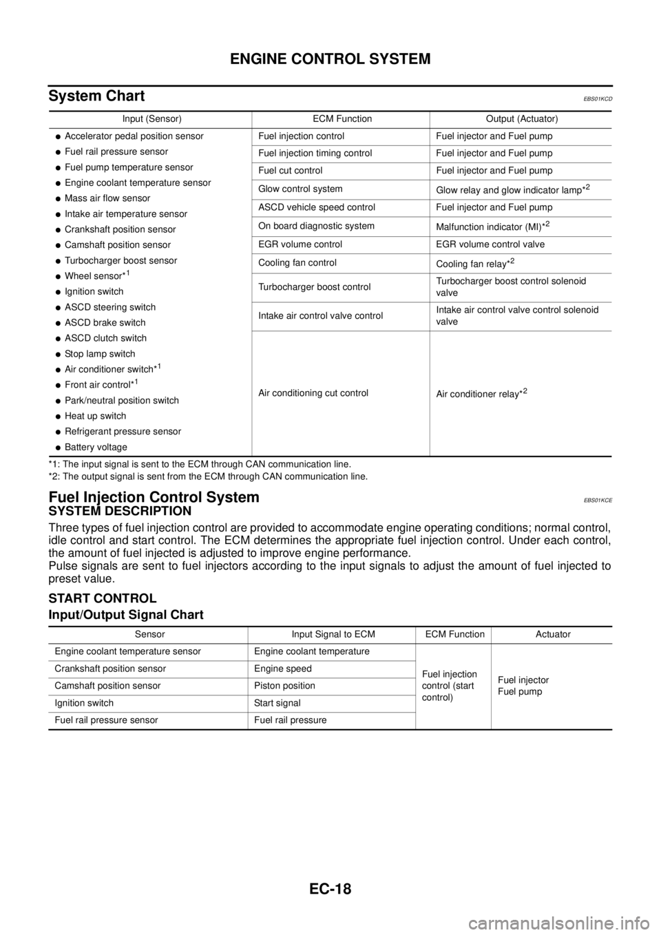
System Chart
EBS01KCD
*1: The input signal is sent to the ECM through CAN communication line.
*2: The output signal is sent from the ECM through CAN communication line.
Fuel Injection Control SystemEBS01KCE
SYSTEM DESCRIPTION
Three types of fuel injection control are provided to accommodate engine operating conditions; normal control,
idle control and start control. The ECM determines the appropriate fuel injection control. Under each control,
the amount of fuel injected is adjusted to improve engine performance.
Pulse signals are sent to fuel injectors according to the input signals to adjust the amount of fuel injected to
preset value.
START CONTROL
Input/Output Signal Chart
Input (Sensor) ECM Function Output (Actuator)
lAccelerator pedal position sensor
lFuel rail pressure sensor
lFuel pump temperature sensor
lEngine coolant temperature sensor
lMass air flow sensor
lIntake air temperature sensor
lCrankshaft position sensor
lCamshaft position sensor
lTurbocharger boost sensor
lWheel sensor*1
lIgnition switch
lASCD steering switch
lASCD brake switch
lASCD clutch switch
lSt o p l a m p s w it c h
lAir conditioner switch*1
lFront air control*1
lPark/neutral position switch
lHeat up switch
lRefrigerant pressure sensor
lBattery voltageFuel injection control Fuel injector and Fuel pump
Fuel injection timing control Fuel injector and Fuel pump
Fuel cut control Fuel injector and Fuel pump
Glow control system
Glow relay and glow indicator lamp*
2
ASCD vehicle speed control Fuel injector and Fuel pump
On board diagnostic system
Malfunction indicator (MI)*
2
EGR volume control EGR volume control valve
Cooling fan control
Cooling fan relay*
2
Turbocharger boost controlTurbocharger boost control solenoid
valve
Intake air control valve controlIntake air control valve control solenoid
valve
Air conditioning cut control
Air conditioner relay*
2
Sensor Input Signal to ECM ECM Function Actuator
Engine coolant temperature sensor Engine coolant temperature
Fuel injection
control (start
control)Fuel injector
Fuel pump Crankshaft position sensor Engine speed
Camshaft position sensor Piston position
Ignition switch Start signal
Fuel rail pressure sensor Fuel rail pressure
Page 999 of 3171
ENGINE CONTROL SYSTEM
EC-19
C
D
E
F
G
H
I
J
K
L
MA
EC
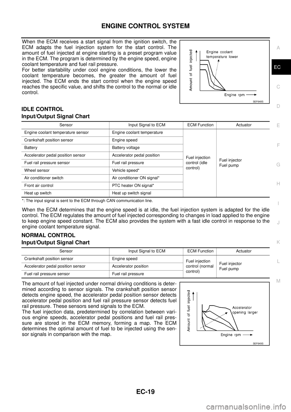
When the ECM receives a start signal from the ignition switch, the
ECM adapts the fuel injection system for the start control. The
amount of fuel injected at engine starting is a preset program value
in the ECM. The program is determined by the engine speed, engine
coolant temperature and fuel rail pressure.
For better startability under cool engine conditions, the lower the
coolant temperature becomes, the greater the amount of fuel
injected. The ECM ends the start control when the engine speed
reaches the specific value, and shifts the control to the normal or idle
control.
IDLE CONTROL
Input/Output Signal Chart
*: The input signal is sent to the ECM through CAN communication line.
When the ECM determines that the engine speed is at idle, the fuel injection system is adapted for the idle
control. The ECM regulates the amount of fuel injected corresponding to changes in load applied to the engine
to keep engine speed constant. The ECM also provides the system with a fast idle control in response to the
engine coolant temperature signal.
NORMAL CONTROL
Input/Output Signal Chart
The amount of fuel injected under normal driving conditions is deter-
mined according to sensor signals. The crankshaft position sensor
detects engine speed, the accelerator pedal position sensor detects
accelerator pedal position and fuel rail pressure sensor detects fuel
rail pressure. These sensors send signals to the ECM.
The fuel injection data, predetermined by correlation between vari-
ous engine speeds, accelerator pedal positions and fuel rail pres-
sure are stored in the ECM memory, forming a map. The ECM
determines the optimal amount of fuel to be injected using the sen-
sor signals in comparison with the map.
SEF648S
Sensor Input Signal to ECM ECM Function Actuator
Engine coolant temperature sensor Engine coolant temperature
Fuel injection
control (idle
control)Fuel injector
Fuel pump Crankshaft position sensor Engine speed
Battery Battery voltage
Accelerator pedal position sensor Accelerator pedal position
Fuel rail pressure sensor Fuel rail pressure
Wheel sensor Vehicle speed*
Air conditioner switch Air conditioner ON signal*
Front air control PTC heater ON signal*
Heat up switch Heat up switch signal
Sensor Input Signal to ECM ECM Function Actuator
Crankshaft position sensor Engine speed
Fuel injection
control (normal
control)Fuel injector
Fuel pump Accelerator pedal position sensor Accelerator position
Fuel rail pressure sensor Fuel rail pressure
SEF649S
Page 1000 of 3171
EC-20
ENGINE CONTROL SYSTEM
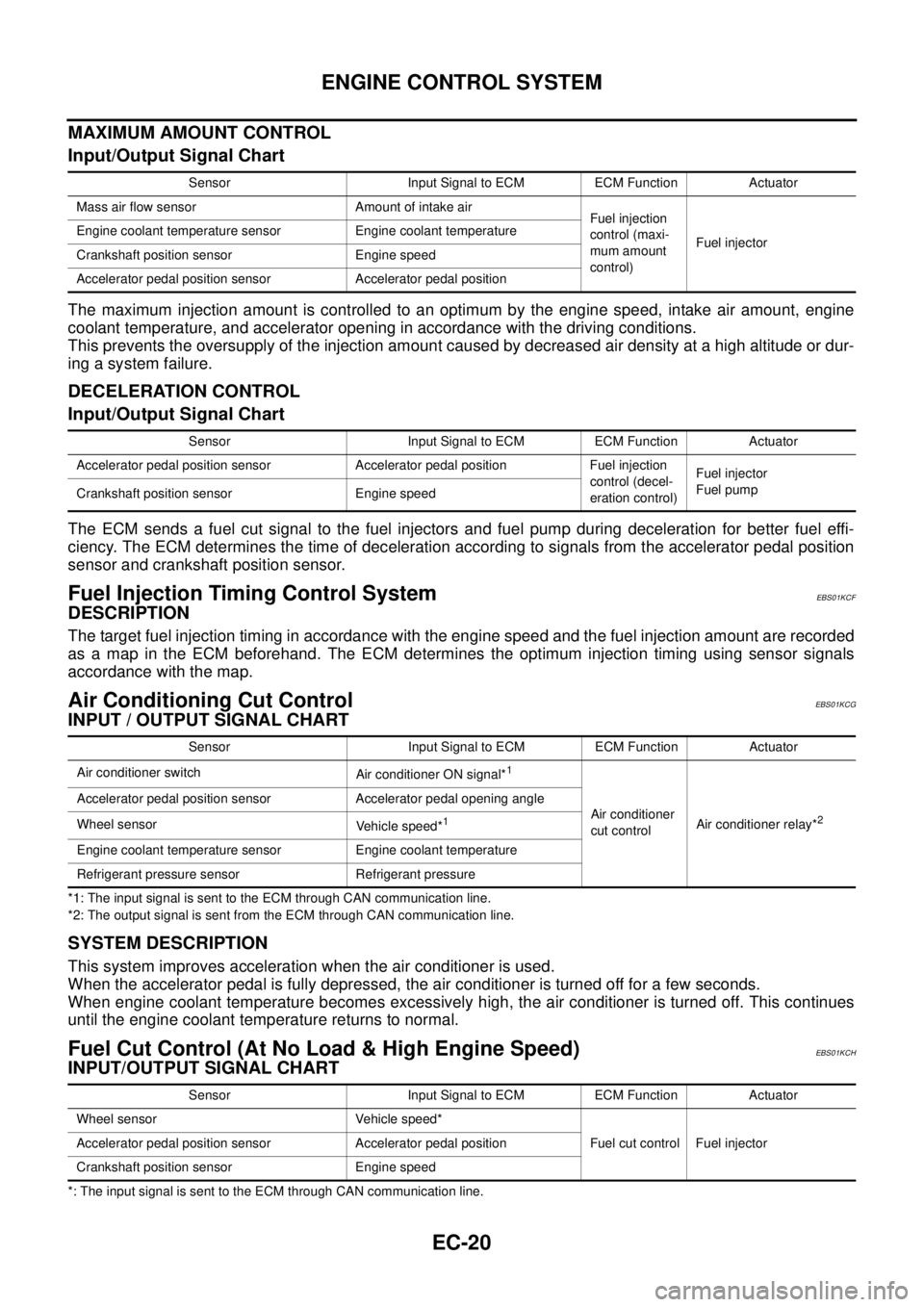
MAXIMUM AMOUNT CONTROL
Input/Output Signal Chart
The maximum injection amount is controlled to an optimum by the engine speed, intake air amount, engine
coolant temperature, and accelerator opening in accordance with the driving conditions.
This prevents the oversupply of the injection amount caused by decreased air density at a high altitude or dur-
ing a system failure.
DECELERATION CONTROL
Input/Output Signal Chart
The ECM sends a fuel cut signal to the fuel injectors and fuel pump during deceleration for better fuel effi-
ciency. The ECM determines the time of deceleration according to signals from the accelerator pedal position
sensor and crankshaft position sensor.
Fuel Injection Timing Control SystemEBS01KCF
DESCRIPTION
The target fuel injection timing in accordance with the engine speed and the fuel injection amount are recorded
as a map in the ECM beforehand. The ECM determines the optimum injection timing using sensor signals
accordance with the map.
Air Conditioning Cut ControlEBS01KCG
INPUT / OUTPUT SIGNAL CHART
*1: The input signal is sent to the ECM through CAN communication line.
*2: The output signal is sent from the ECM through CAN communication line.
SYSTEM DESCRIPTION
This system improves acceleration when the air conditioner is used.
When the accelerator pedal is fully depressed, the air conditioner is turned off for a few seconds.
When engine coolant temperature becomes excessively high, the air conditioner is turned off. This continues
until the engine coolant temperature returns to normal.
Fuel Cut Control (At No Load & High Engine Speed)EBS01KCH
INPUT/OUTPUT SIGNAL CHART
*: The input signal is sent to the ECM through CAN communication line.Sensor Input Signal to ECM ECM Function Actuator
Mass air flow sensor Amount of intake air
Fuel injection
control (maxi-
mum amount
control)Fuel injector Engine coolant temperature sensor Engine coolant temperature
Crankshaft position sensor Engine speed
Accelerator pedal position sensor Accelerator pedal position
Sensor Input Signal to ECM ECM Function Actuator
Accelerator pedal position sensor Accelerator pedal position Fuel injection
control (decel-
eration control)Fuel injector
Fuel pump
Crankshaft position sensor Engine speed
Sensor Input Signal to ECM ECM Function Actuator
Air conditioner switch
Air conditioner ON signal*
1
Air conditioner
cut controlAir conditioner relay*2
Accelerator pedal position sensor Accelerator pedal opening angle
Wheel sensor
Vehicle speed*
1
Engine coolant temperature sensor Engine coolant temperature
Refrigerant pressure sensor Refrigerant pressure
Sensor Input Signal to ECM ECM Function Actuator
Wheel sensor Vehicle speed*
Fuel cut control Fuel injector Accelerator pedal position sensor Accelerator pedal position
Crankshaft position sensor Engine speed
Page 1005 of 3171
BASIC SERVICE PROCEDURE
EC-25
C
D
E
F
G
H
I
J
K
L
MA
EC
Injector Adjustment Value RegistrationEBS01KCM
DESCRIPTION
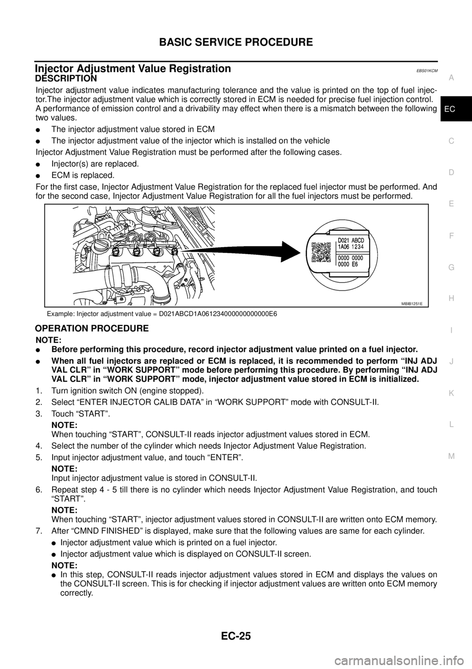
Injector adjustment value indicates manufacturing tolerance and the value is printed on the top of fuel injec-
tor.The injector adjustment value which is correctly stored in ECM is needed for precise fuel injection control.
A performance of emission control and a drivability may effect when there is a mismatch between the following
two values.
lThe injector adjustment value stored in ECM
lThe injector adjustment value of the injector which is installed on the vehicle
Injector Adjustment Value Registration must be performed after the following cases.
lInjector(s) are replaced.
lECM is replaced.
For the first case, Injector Adjustment Value Registration for the replaced fuel injector must be performed. And
for the second case, Injector Adjustment Value Registration for all the fuel injectors must be performed.
OPERATION PROCEDURE
NOTE:
lBefore performing this procedure, record injector adjustment value printed on a fuel injector.
lWhen all fuel injectors are replaced or ECM is replaced, it is recommended to perform “INJ ADJ
VAL CLR” in “WORK SUPPORT” mode before performing this procedure. By performing “INJ ADJ
VAL CLR” in “WORK SUPPORT” mode, injector adjustment value stored in ECM is initialized.
1. Turn ignition switch ON (engine stopped).
2. Select “ENTER INJECTOR CALIB DATA” in “WORK SUPPORT” mode with CONSULT-II.
3. Touch “START”.
NOTE:
When touching “START”, CONSULT-II reads injector adjustment values stored in ECM.
4. Select the number of the cylinder which needs Injector Adjustment Value Registration.
5. Input injector adjustment value, and touch “ENTER”.
NOTE:
Input injector adjustment value is stored in CONSULT-II.
6. Repeat step 4 - 5 till there is no cylinder which needs Injector Adjustment Value Registration, and touch
“START”.
NOTE:
When touching “START”, injector adjustment values stored in CONSULT-II are written onto ECM memory.
7. After “CMND FINISHED” is displayed, make sure that the following values are same for each cylinder.
lInjector adjustment value which is printed on a fuel injector.
lInjector adjustment value which is displayed on CONSULT-II screen.
NOTE:
lIn this step, CONSULT-II reads injector adjustment values stored in ECM and displays the values on
the CONSULT-II screen. This is for checking if injector adjustment values are written onto ECM memory
correctly.
Example: Injector adjustment value = D021ABCD1A061234000000000000E6
MBIB1251E
Page 1017 of 3171
TROUBLE DIAGNOSIS
EC-37
C
D
E
F
G
H
I
J
K
L
MA
EC
DTC Inspection Priority ChartEBS01KCU
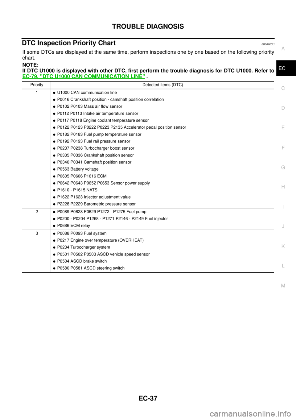
If some DTCs are displayed at the same time, perform inspections one by one based on the following priority
chart.
NOTE:
If DTC U1000 is displayed with other DTC, first perform the trouble diagnosis for DTC U1000. Refer to
EC-79, "
DTC U1000 CAN COMMUNICATION LINE".
Priority Detected items (DTC)
1
lU1000 CAN communication line
lP0016 Crankshaft position - camshaft position correlation
lP0102 P0103 Mass air flow sensor
lP0112 P0113 Intake air temperature sensor
lP0117 P0118 Engine coolant temperature sensor
lP0122 P0123 P0222 P0223 P2135 Accelerator pedal position sensor
lP0182 P0183 Fuel pump temperature sensor
lP0192 P0193 Fuel rail pressure sensor
lP0237 P0238 Turbocharger boost sensor
lP0335 P0336 Crankshaft position sensor
lP0340 P0341 Camshaft position sensor
lP0563 Battery voltage
lP0605 P0606 P1616 ECM
lP0642 P0643 P0652 P0653 Sensor power supply
lP1610 - P1615 NATS
lP1622 P1623 Injector adjustment value
lP2228 P2229 Barometric pressure sensor
2
lP0089 P0628 P0629 P1272 - P1275 Fuel pump
lP0200 - P0204 P1268 - P1271 P2146 - P2149 Fuel injector
lP0686 ECM relay
3
lP0088 P0093 Fuel system
lP0217 Engine over temperature (OVERHEAT)
lP0234 Turbocharger system
lP0501 P0502 P0503 ASCD vehicle speed sensor
lP0504 ASCD brake switch
lP0580 P0581 ASCD steering switch
Page 1021 of 3171
TROUBLE DIAGNOSIS
EC-41
C
D
E
F
G
H
I
J
K
L
MA
EC
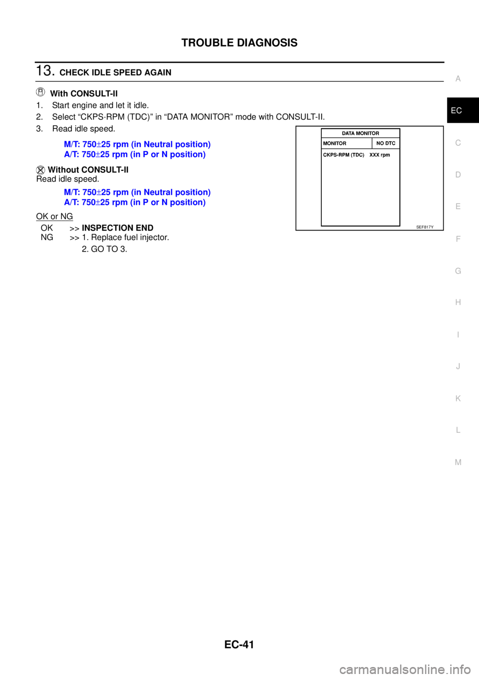
13.CHECK IDLE SPEED AGAIN
With CONSULT-II
1. Start engine and let it idle.
2. Select “CKPS·RPM (TDC)” in “DATA MONITOR” mode with CONSULT-II.
3. Read idle speed.
Without CONSULT-II
Read idle speed.
OK or NG
OK >>INSPECTION END
NG >> 1. Replace fuel injector.
2. GO TO 3. M/T: 750±25 rpm (in Neutral position)
A/T: 750±25 rpm (in P or N position)
M/T: 750±25 rpm (in Neutral position)
A/T: 750±25 rpm (in P or N position)SEF817Y
Page 1022 of 3171
EC-42
TROUBLE DIAGNOSIS
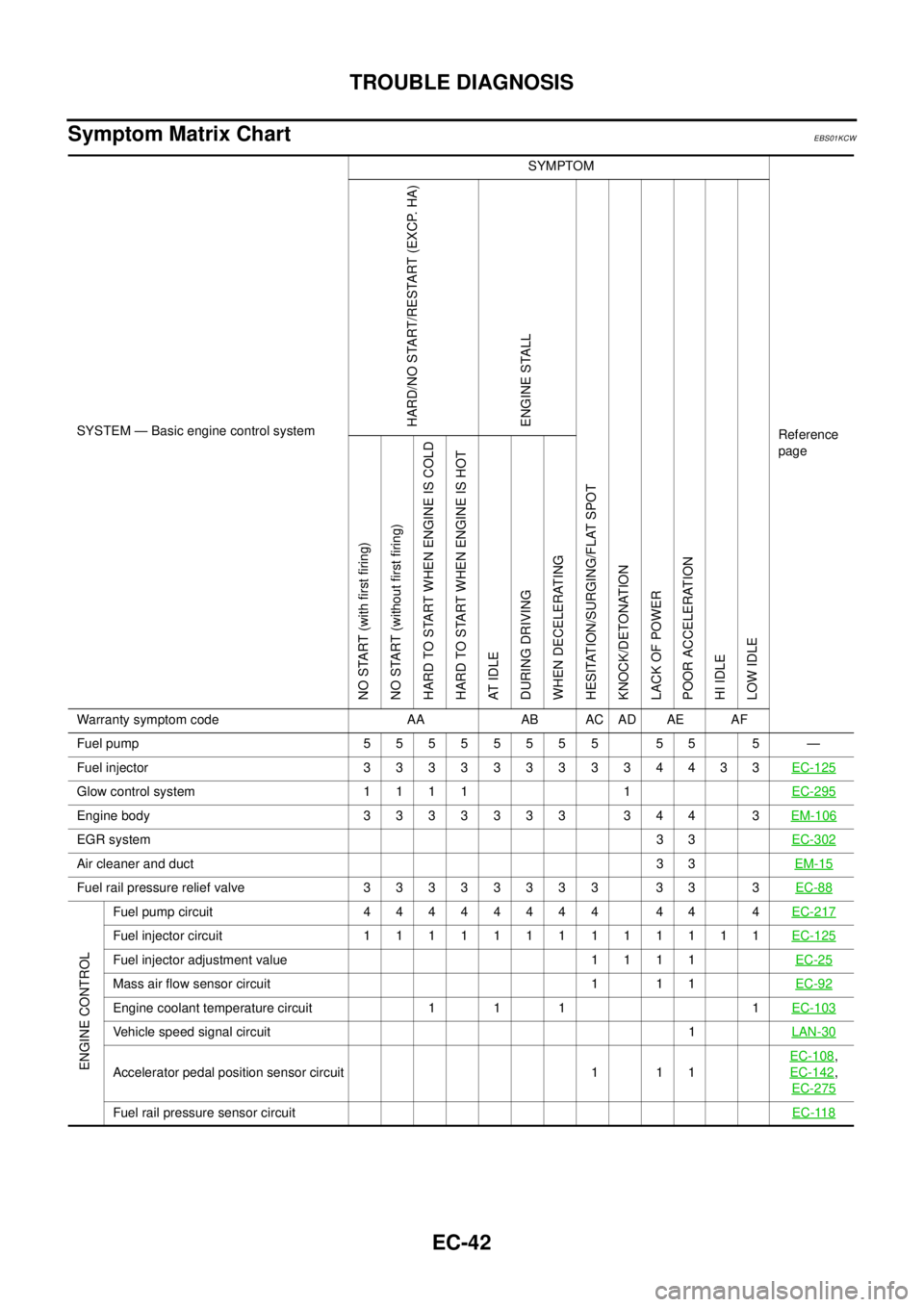
Symptom Matrix Chart
EBS01KCW
SYSTEM — Basic engine control systemSYMPTOM
Reference
pageHARD/NO START/RESTART (EXCP. HA)
ENGINE STALL
HESITATION/SURGING/FLAT SPOT
KNOCK/DETONATION
LACK OF POWER
POOR ACCELERATION
HI IDLE
LOW IDLE NO START (with first firing)
NO START (without first firing)
HARD TO START WHEN ENGINE IS COLD
HARD TO START WHEN ENGINE IS HOT
AT I D L E
DURING DRIVING
WHEN DECELERATING
Warranty symptom code AA AB AC AD AE AF
Fuelpump 55555555 55 5 —
Fuelinjector 3333333334433EC-125
Glow control system 1 1 1 1 1EC-295
Engine body 3 3 3 3 3 3 3 3 4 4 3EM-106
EGR system33EC-302
Air cleaner and duct33EM-15
Fuel rail pressure relief valve 3 3 3 3 3 3 3 3 3 3 3EC-88
ENGINE CONTROL
Fuelpumpcircuit 44444444 44 4EC-217
Fuelinjectorcircuit 1111111111111EC-125
Fuel injector adjustment value 1 1 1 1EC-25
Mass air flow sensor circuit 1 1 1EC-92
Engine coolant temperature circuit 1 1 1 1EC-103
Vehicle speed signal circuit1LAN-30
Accelerator pedal position sensor circuit 1 1 1EC-108
,
EC-142
,
EC-275
Fuel rail pressure sensor circuitEC-118