2005 NISSAN NAVARA fuse
[x] Cancel search: fusePage 1329 of 3171
START SIGNAL
EC-349
C
D
E
F
G
H
I
J
K
L
MA
EC
Diagnostic ProcedureEBS01KMX
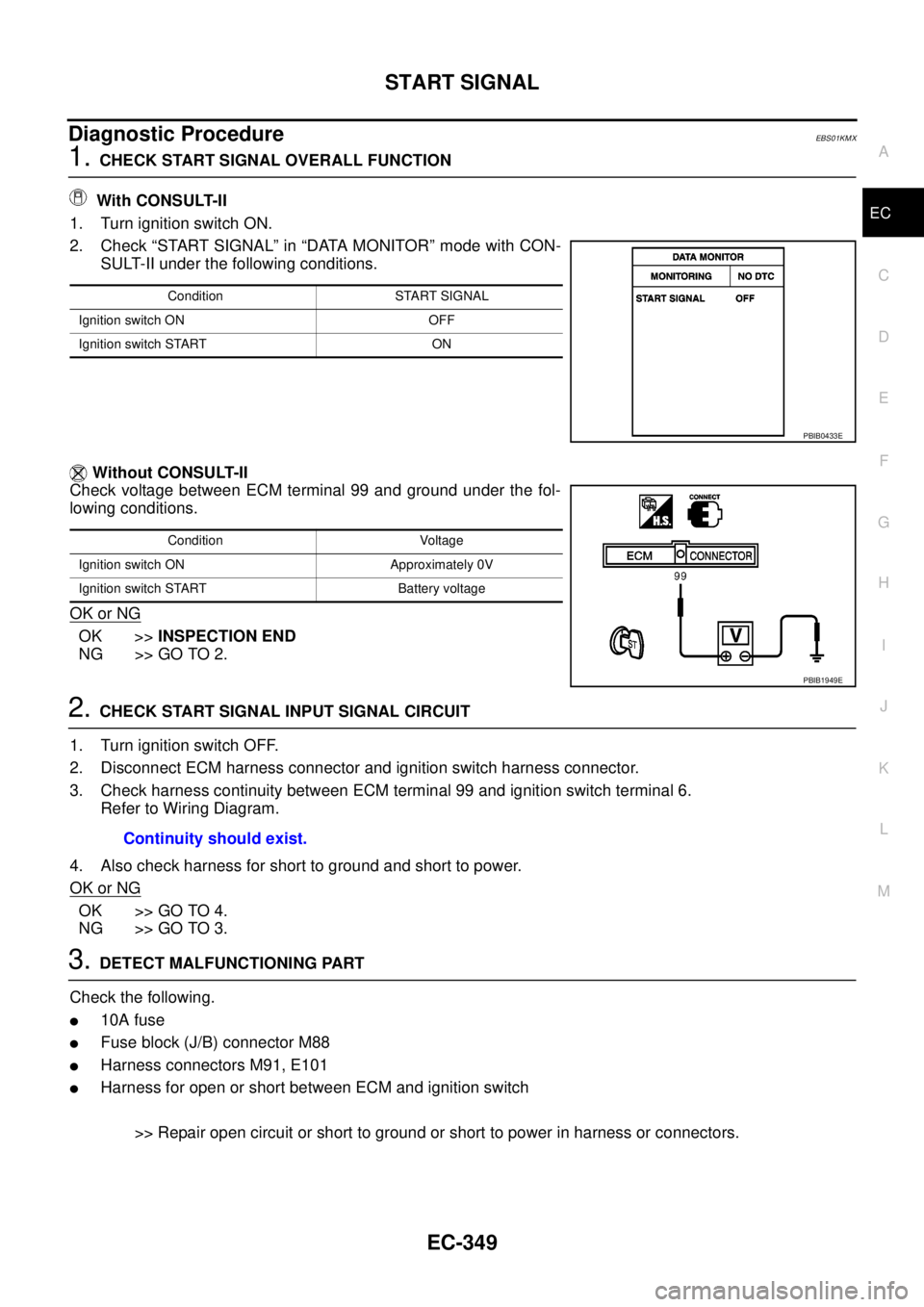
1.CHECK START SIGNAL OVERALL FUNCTION
With CONSULT-II
1. Turn ignition switch ON.
2. Check “START SIGNAL” in “DATA MONITOR” mode with CON-
SULT-II under the following conditions.
Without CONSULT-II
Check voltage between ECM terminal 99 and ground under the fol-
lowing conditions.
OK or NG
OK >>INSPECTION END
NG >> GO TO 2.
2.CHECK START SIGNAL INPUT SIGNAL CIRCUIT
1. Turn ignition switch OFF.
2. Disconnect ECM harness connector and ignition switch harness connector.
3. Check harness continuity between ECM terminal 99 and ignition switch terminal 6.
Refer to Wiring Diagram.
4. Also check harness for short to ground and short to power.
OK or NG
OK >> GO TO 4.
NG >> GO TO 3.
3.DETECT MALFUNCTIONING PART
Check the following.
l10A fuse
lFuse block (J/B) connector M88
lHarness connectors M91, E101
lHarness for open or short between ECM and ignition switch
>> Repair open circuit or short to ground or short to power in harness or connectors.
Condition START SIGNAL
Ignition switch ON OFF
Ignition switch START ON
PBIB0433E
Condition Voltage
Ignition switch ON Approximately 0V
Ignition switch START Battery voltage
PBIB1949E
Continuity should exist.
Page 1452 of 3171
EM-70
OIL SEAL
OIL SEAL
PFP:12279
Removal and Installation of Valve Oil SealEBS01EK7
REMOVAL
1. Turn crankshaft until the cylinder requiring new valve oil seals is at TDC. This will prevent valve from drop-
ping into cylinder.
2. Remove camshafts. Refer toEM-59, "
CAMSHAFT".
3. Remove adjusting shims and valve lifters. Refer toEM-59, "
CAMSHAFT".
lCheck the installation positions, and keep them to avoid being confused.
4. Rotate crankshaft, and set piston whose valve oil seal is to be removed to TDC. This will prevent valve
from dropping into cylinder.
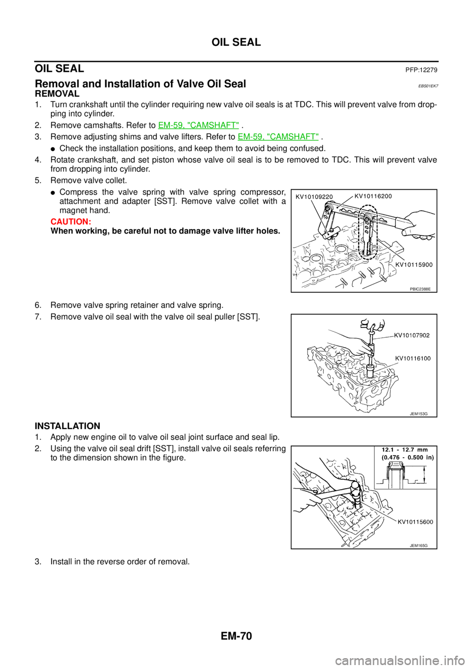
5. Remove valve collet.
lCompress the valve spring with valve spring compressor,
attachment and adapter [SST]. Remove valve collet with a
magnet hand.
CAUTION:
When working, be careful not to damage valve lifter holes.
6. Remove valve spring retainer and valve spring.
7. Remove valve oil seal with the valve oil seal puller [SST].
INSTALLATION
1. Apply new engine oil to valve oil seal joint surface and seal lip.
2. Using the valve oil seal drift [SST], install valve oil seals referring
to the dimension shown in the figure.
3. Install in the reverse order of removal.
PBIC2388E
JEM153G
JEM165G
Page 1474 of 3171
EM-92
CYLINDER HEAD
CYLINDER HEAD
PFP:11041
On-Vehicle ServiceEBS01E6A
CHECKING COMPRESSION PRESSURE
1. Warm up engine thoroughly. Then, stop it.
2. Using CONSULT-II, make sure no error codes are indicated for self-diagnosis items. Refer toEC-38,
"Basic Inspection".
lDo not disconnect CONSULT-II until the end of this operation; it will be used to check engine rpm and
for error detection at the end of this operation.
3. Disconnect the battery cable from the negative terminal.
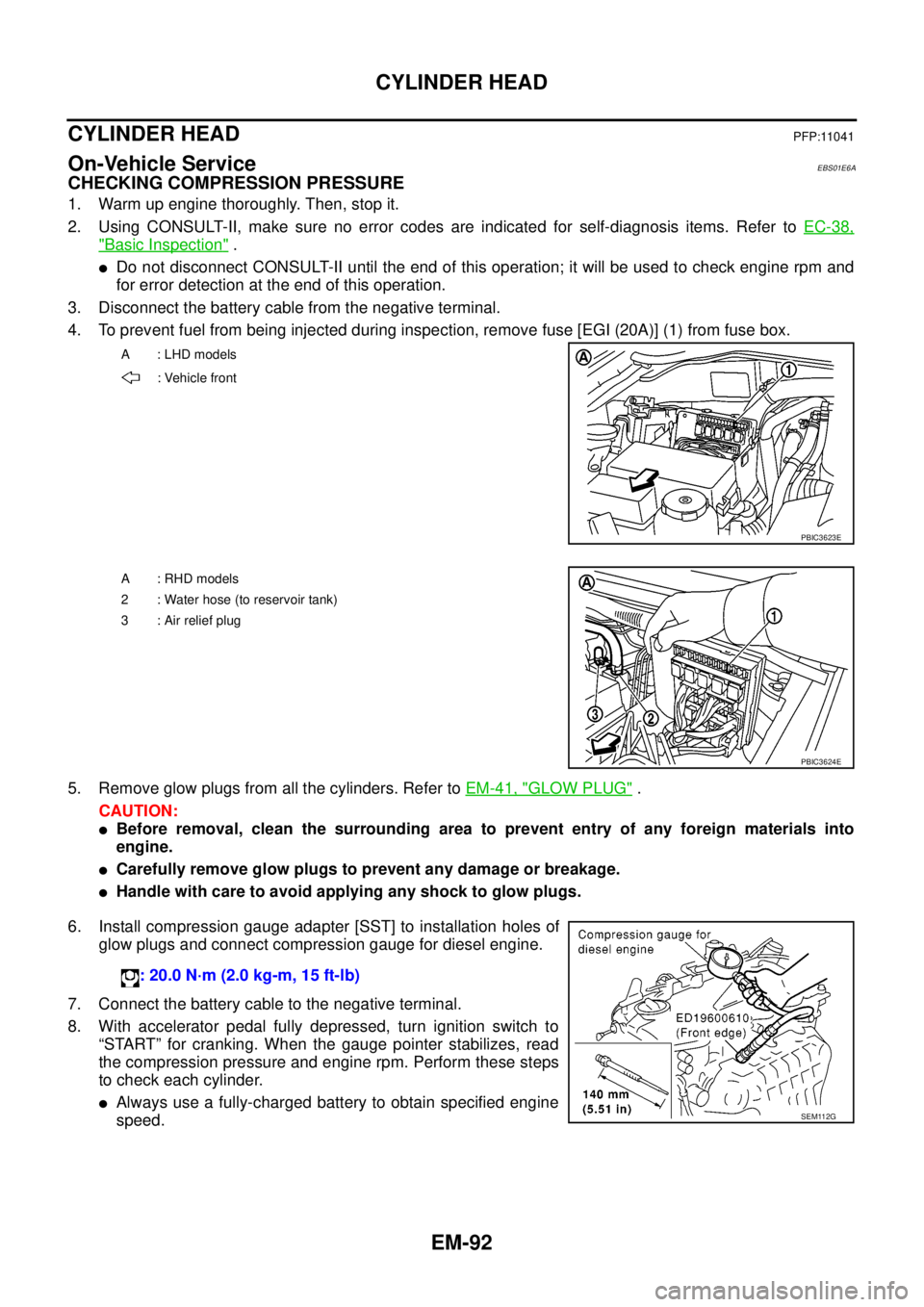
4. To prevent fuel from being injected during inspection, remove fuse [EGI (20A)] (1) from fuse box.
5. Remove glow plugs from all the cylinders. Refer toEM-41, "
GLOW PLUG".
CAUTION:
lBefore removal, clean the surrounding area to prevent entry of any foreign materials into
engine.
lCarefully remove glow plugs to prevent any damage or breakage.
lHandle with care to avoid applying any shock to glow plugs.
6. Install compression gauge adapter [SST] to installation holes of
glow plugs and connect compression gauge for diesel engine.
7. Connect the battery cable to the negative terminal.
8. With accelerator pedal fully depressed, turn ignition switch to
“START” for cranking. When the gauge pointer stabilizes, read
the compression pressure and engine rpm. Perform these steps
to check each cylinder.
lAlways use a fully-charged battery to obtain specified engine
speed.
A : LHD models
: Vehicle front
PBIC3623E
A : RHD models
2 : Water hose (to reservoir tank)
3:Airreliefplug
PBIC3624E
: 20.0 N·m (2.0 kg-m, 15 ft-lb)
SEM112G
Page 1475 of 3171
CYLINDER HEAD
EM-93
C
D
E
F
G
H
I
J
K
L
MA
EM
Compression pressure
Unit: kPa (bar, kg/cm2, psi)/rpm
lWhen engine rpm is out of the specified range, check the specific gravity of battery liquid. Measure
again under corrected conditions.
lIf engine rpm exceeds the limit, check valve clearance and combustion chamber components (valves,
valve seats, cylinder head gaskets, piston rings, pistons, cylinder bores, cylinder block upper and lower
surfaces) and measure again.
lIf compression pressure is low in some cylinders, apply engine oil from glow plug installation hole. Then
check pressure again.
–If compression pressure becomes normal after applying engine oil, piston ring may be worn or dam-
aged. Check piston ring for malfunction. If any, replace piston ring.
–If compression pressure is still low after applying engine oil, valve may be malfunctioning. Check valve
for malfunction. If contact malfunction is found, replace valve or valve seat.
lIf compression pressure in adjacent two cylinders is low after applying engine oil, pressure may be
leaking from gasket. In this case, replace cylinder head gasket.
9. Complete this operation as follows:
a. Turn the ignition switch to “OFF”.
b. Disconnect the battery cable from the negative terminal.
c. Install glow plug and install all the parts removed in step 4.
d. Install fuse [EGI (20A)].
e. Connect the battery cable to the negative terminal.
f. Using CONSULT-II make sure no DTC is indicated for items of self-diagnosis.
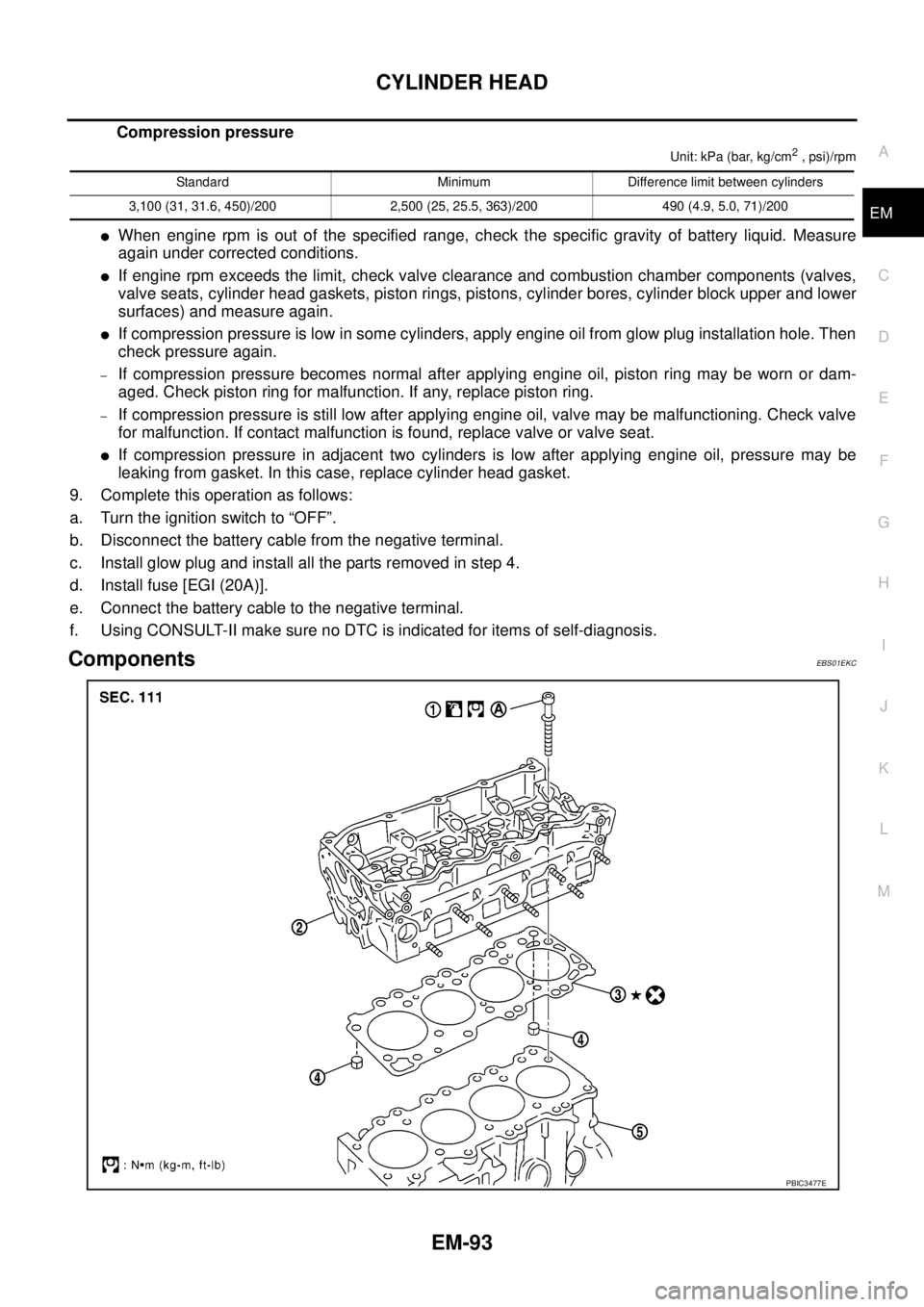
ComponentsEBS01EKC
Standard Minimum Difference limit between cylinders
3,100 (31, 31.6, 450)/200 2,500 (25, 25.5, 363)/200 490 (4.9, 5.0, 71)/200
PBIC3477E
Page 1481 of 3171

CYLINDER HEAD
EM-99
C
D
E
F
G
H
I
J
K
L
MA
EM
ComponentsEBS01EKD
Disassembly and AssemblyEBS01E6C
DISASSEMBLY
1. Remove adjusting shims and valve lifters.
lCheck the installation positions, and keep them to avoid being confused.
2. Remove valve collet.
lUsing the valve spring compressor [SST], compress valve
spring. Using magnet hand, remove valve collets.
3. Remove valve spring retainers and valve springs.
4. Remove valves as pressing valve stems toward combustion chamber.
lBefore removing valve, check the valve guide clearance. Refer toEM-101, "Valve Guide Clearance".
1. Adjusting shim 2. Valve lifter 3. Valve collet
4. Valve spring retainer 5. Valve spring 6. Valve oil seal
7. Valve spring seat 8. Valve guide 9. Cylinder head
10. Valve seat 11. Valve (Exhaust) 12. Valve (Intake)
PBIC2328E
PBIC2388E
Page 1639 of 3171
HOW TO USE THIS MANUAL
GI-17
C
D
E
F
G
H
I
J
K
L
MB
GI
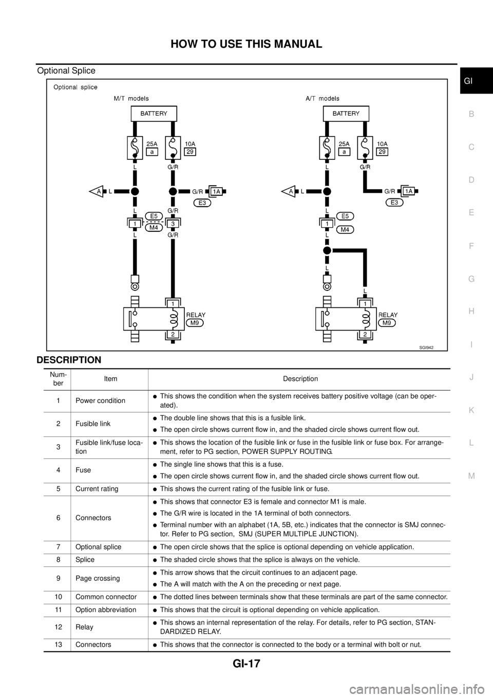
Optional Splice
DESCRIPTION
SGI942
Num-
berItem Description
1 Power condition
lThis shows the condition when the system receives battery positive voltage (can be oper-
ated).
2 Fusible link
lThe double line shows that this is a fusible link.
lThe open circle shows current flow in, and the shaded circle shows current flow out.
3Fusible link/fuse loca-
tion
lThis shows the location of the fusible link or fuse in the fusible link or fuse box. For arrange-
ment, refer to PG section, POWER SUPPLY ROUTING.
4Fuse
lThe single line shows that this is a fuse.
lThe open circle shows current flow in, and the shaded circle shows current flow out.
5 Current rating
lThis shows the current rating of the fusible link or fuse.
6 Connectors
lThis shows that connector E3 is female and connector M1 is male.
lThe G/R wire is located in the 1A terminal of both connectors.
lTerminal number with an alphabet (1A, 5B, etc.) indicates that the connector is SMJ connec-
tor. Refer to PG section, SMJ (SUPER MULTIPLE JUNCTION).
7 Optional splice
lThe open circle shows that the splice is optional depending on vehicle application.
8Splice
lThe shaded circle shows that the splice is always on the vehicle.
9 Page crossing
lThis arrow shows that the circuit continues to an adjacent page.
lThe A will match with the A on the preceding or next page.
10 Common connector
lThe dotted lines between terminals show that these terminals are part of the same connector.
11 Option abbreviation
lThis shows that the circuit is optional depending on vehicle application.
12 Relay
lThis shows an internal representation of the relay. For details, refer to PG section, STAN-
DARDIZED RELAY.
13 Connectors
lThis shows that the connector is connected to the body or a terminal with bolt or nut.
Page 1640 of 3171

GI-18
HOW TO USE THIS MANUAL
14 Wire color
lThis shows a code for the color of the wire.
B=Black
W=White
R=Red
G = Green
L=Blue
Y = Yellow
LG = Light GreenBR = Brown
OR or O = Orange
P=Pink
PU or V (Violet) = Purple
GY or GR = Gray
SB = Sky Blue
CH = Dark Brown
DG = Dark Green
When the wire color is striped, the base color is given first, followed by the stripe color as shown
below:
Example: L/W = Blue with White Stripe
15 Option description
lThis shows a description of the option abbreviation used on the page.
16 Switch
lThis shows that continuity exists between terminals 1 and 2 when the switch is in the A posi-
tion. Continuity exists between terminals 1 and 3 when the switch is in the B position.
17 Assembly parts
lConnector terminal in component shows that it is a harness incorporated assembly.
18 Cell code
lThis identifies each page of the wiring diagram by section, system and wiring diagram page
number.
19 Current flow arrow
lArrow indicates electric current flow, especially where the direction of standard flow (vertically
downward or horizontally from left to right) is difficult to follow.
lA double arrow “ ” shows that current can flow in either direction depending on cir-
cuit operation.
20 System branch
lThis shows that the system branches to another system identified by cell code (section and
system).
21 Page crossing
lThis arrow shows that the circuit continues to another page identified by cell code.
lThe C will match with the C on another page within the system other than the next or preced-
ing pages.
22 Shielded line
lThe line enclosed by broken line circle shows shield wire.
23Component box in
wave line
lThis shows that another part of the component is also shown on another page (indicated by
wave line) within the system.
24 Component name
lThis shows the name of a component.
25 Connector number
lThis shows the connector number.
lThe letter shows which harness the connector is located in.
lExample:M: main harness. For detail and to locate the connector, refer to PG section "Main
Harness", “Harness Layout”. A coordinate grid is included for complex harnesses to aid in
locating connectors.
26 Ground (GND)
lThe line spliced and grounded under wire color shows that ground line is spliced at the
grounded connector.
27 Ground (GND)
lThis shows the ground connection. For detailed ground distribution information, refer to
"Ground Distribution" in PG section.
28 Connector views
lThis area shows the connector faces of the components in the wiring diagram on the page.
29 Common component
lConnectors enclosed in broken line show that these connectors belong to the same compo-
nent.
30 Connector color
lThis shows a code for the color of the connector. For code meaning, refer to wire color codes,
Number 14 of this chart.
31Fusible link and fuse
box
lThis shows the arrangement of fusible link(s) and fuse(s), used for connector views of
"POWER SUPPLY ROUTING" in PG section.
The open square shows current flow in, and the shaded square shows current flow out.
32 Reference area
lThis shows that more information on the Super Multiple Junction (SMJ) and Joint Connectors
(J/C) exists on the PG section. Refer to "Reference Area" for details. Num-
berItem Description
Page 1649 of 3171
SERVICE INFORMATION FOR ELECTRICAL INCIDENT
GI-27
C
D
E
F
G
H
I
J
K
L
MB
GI
Cold or Hot Start Up
On some occasions an electrical incident may occur only when the car is started cold, or it may occur when
the car is restarted hot shortly after being turned off. In these cases you may have to keep the car overnight to
make a proper diagnosis.
CIRCUIT INSPECTION
Introduction
In general, testing electrical circuits is an easy task if it is approached in a logical and organized method.
Before beginning it is important to have all available information on the system to be tested. Also, get a thor-
ough understanding of system operation. Then you will be able to use the appropriate equipment and follow
the correct test procedure.
You may have to simulate vehicle vibrations while testing electrical components. Gently shake the wiring har-
ness or electrical component to do this.
NOTE:
Refer to “How to Check Terminal” to probe or check terminal.
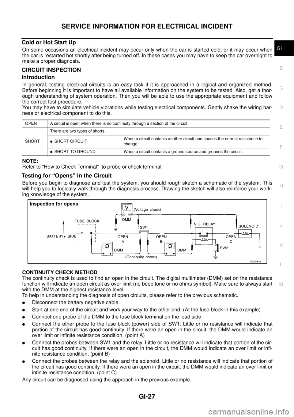
Testing for “Opens” in the Circuit
Before you begin to diagnose and test the system, you should rough sketch a schematic of the system. This
will help you to logically walk through the diagnosis process. Drawing the sketch will also reinforce your work-
ing knowledge of the system.
CONTINUITY CHECK METHOD
The continuity check is used to find an open in the circuit. The digital multimeter (DMM) set on the resistance
function will indicate an open circuit as over limit (no beep tone or no ohms symbol). Make sure to always start
with the DMM at the highest resistance level.
To help in understanding the diagnosis of open circuits, please refer to the previous schematic.
lDisconnect the battery negative cable.
lStart at one end of the circuit and work your way to the other end. (At the fuse block in this example)
lConnect one probe of the DMM to the fuse block terminal on the load side.
lConnect the other probe to the fuse block (power) side of SW1. Little or no resistance will indicate that
portion of the circuit has good continuity. If there were an open in the circuit, the DMM would indicate an
over limit or infinite resistance condition. (point A)
lConnect the probes between SW1 and the relay. Little or no resistance will indicate that portion of the cir-
cuit has good continuity. If there were an open in the circuit, the DMM would indicate an over limit or infi-
nite resistance condition. (point B)
lConnect the probes between the relay and the solenoid. Little or no resistance will indicate that portion of
the circuit has good continuity. If there were an open in the circuit, the DMM would indicate an over limit or
infinite resistance condition. (point C)
Any circuit can be diagnosed using the approach in the previous example.
OPEN A circuit is open when there is no continuity through a section of the circuit.
SHORTThere are two types of shorts.
lSHORT CIRCUITWhen a circuit contacts another circuit and causes the normal resistance to
change.
lSHORT TO GROUND When a circuit contacts a ground source and grounds the circuit.
SGI846-A