2005 NISSAN NAVARA fuse
[x] Cancel search: fusePage 1745 of 3171
REAR WINDOW DEFOGGER
GW-59
C
D
E
F
G
H
J
K
L
MA
B
GW
Rear Window Defogger Power Supply Circuit CheckEIS00B8Q
1.CHECK FUSE
lCheck 15A fuse (No.46, 47, located in the IPDM E/R)
NOTE:
Refer toGW-47, "
Component Parts and Harness Connector Location".
OK or NG
OK >> GO TO 2.
NG >> If fuse is blown, be sure to eliminate cause of malfunction before installing new fuse, refer toPG-
4, "POWER SUPPLY ROUTING CIRCUIT".
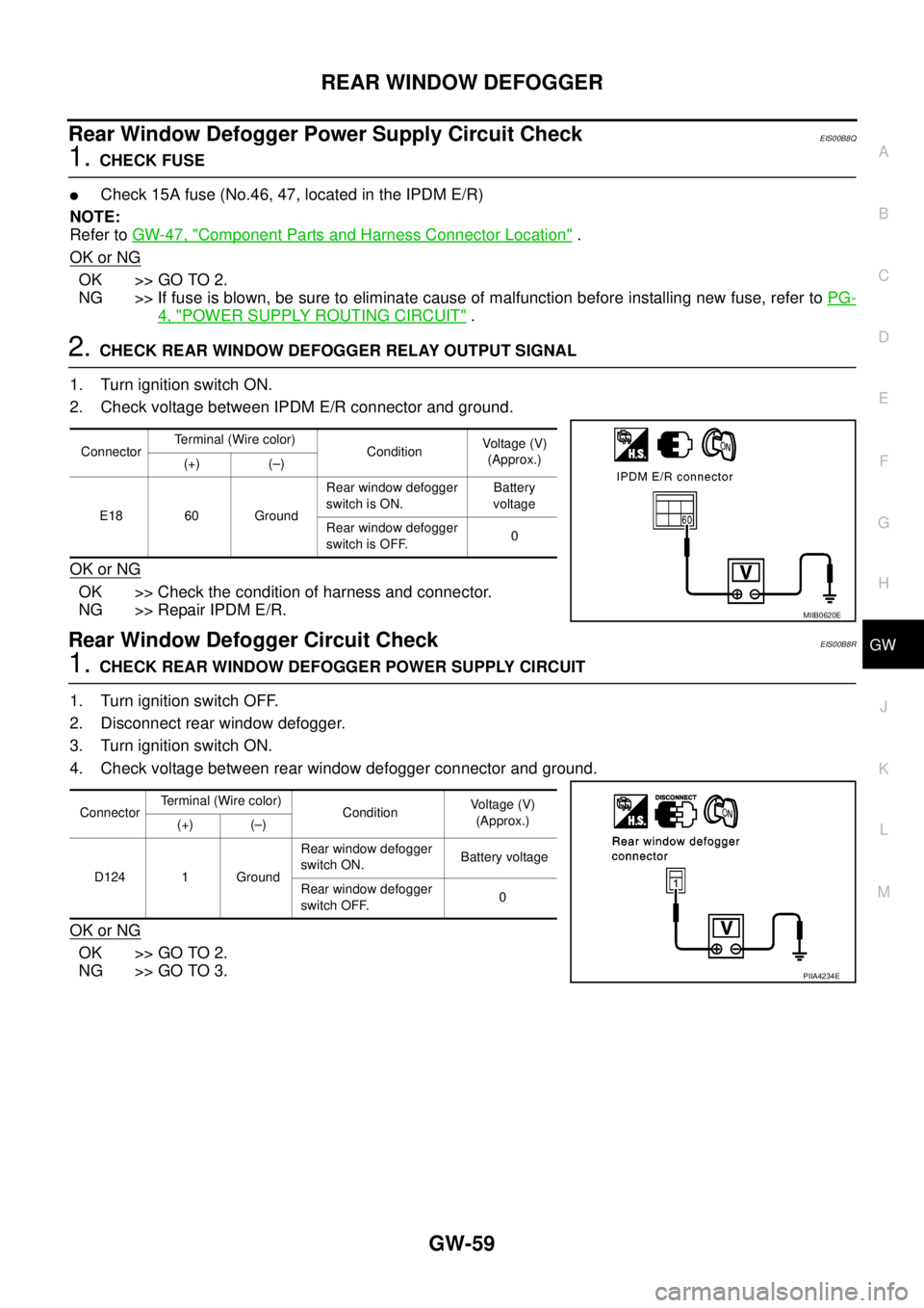
2.CHECK REAR WINDOW DEFOGGER RELAY OUTPUT SIGNAL
1. Turn ignition switch ON.
2. Check voltage between IPDM E/R connector and ground.
OK or NG
OK >> Check the condition of harness and connector.
NG >> Repair IPDM E/R.
Rear Window Defogger Circuit CheckEIS00B8R
1.CHECK REAR WINDOW DEFOGGER POWER SUPPLY CIRCUIT
1. Turn ignition switch OFF.
2. Disconnect rear window defogger.
3. Turn ignition switch ON.
4. Check voltage between rear window defogger connector and ground.
OK or NG
OK >> GO TO 2.
NG >> GO TO 3.
ConnectorTerminal (Wire color)
ConditionVoltag e (V)
(Approx.)
(+) (–)
E18 60 GroundRear window defogger
switch is ON.Battery
voltage
Rear window defogger
switch is OFF.0
MIIB0620E
ConnectorTerminal (Wire color)
ConditionVo l ta g e (V )
(Approx.)
(+) (–)
D124 1 GroundRear window defogger
switch ON.Battery voltage
Rear window defogger
switch OFF.0
PIIA4234E
Page 1756 of 3171
IDX-4
ALPHABETICAL INDEX
Engine control system diagram and chart .........EC-15
Engine coolant ....................................................CO-7
Engine coolant temperature sensor (ECTS) ....EC-103
Engine oil .............................................................LU-5
Engine oil filter replacement .............................MA-26
Engine oil precautions ..........................................GI-7
Engine removal ...............................................EM-106
Engine room cover ............................................EM-20
Engine serial number ..........................................GI-58
Evaporator ....................................ATC-149,MTC-129
Exhaust manifold ..............................................EM-34
Exhaust system ...................................................EX-2
Exhaust system inspection ..................................EX-2
Expansion valve ............................ATC-150,MTC-130
F
F/FOG - Wiring diagram .....................................LT-74
F/PUMP - Wiring diagram ..EC-248,EC-254,EC-260,
EC-266
Final drive pre-inspection .................................FFD-18
Final drive removal and installation ..RFD-14,RFD-81
Flow charts .........................................................GI-24
Fluid temperature sensor (A/T) ........................AT-118
Fluids ................................................................MA-14
Fluorescent leak detector .............ATC-150,MTC-131
Flywheel (clutch) ................................................CL-17
Flywheel runout ..............................................EM-134
Fog lamp, front ....................................................LT-71
Foot lamp ..........................................................LT-145
Fork rod (M/T) ....................................................MT-23
Freeze frame data .............................................EC-28
Front brake solenoid valve .................AT-137,AT-139
Front bumper ......................................................EI-15
Front case (Transfer) ..........................TF-114,TF-120
Front combination lamp removal and installationLT-30
Front door ................BL-118,BL-120,BL-126,GW-35
Front Door Trim ..................................................EI-30
Front drive shaft (Transfer) ...TF-114,TF-120,TF-133
Front final drive removal and installation (4WD) ...........
FFD-15
Front fog lamp .....................................................LT-71
Front passenger air bag ..................................SRS-40
Front seat ...........................................................SE-20
Front seat belt ............................................SB-3,SB-5
Front seat belt pre-tensioner ...............SRS-3,SRS-47
Front side air bag ............................................SRS-43
Front washer ......................................................WW-4
Front wiper .........................................................WW-4
FRPS - Wiring diagram ....................................EC-120
FTS - Wiring diagram .......................................EC-115
Fuel cut control (at no load high engine speed) .EC-20
Fuel filler lid ......................................................BL-136
Fuel filter ............................................................EC-23
Fuel filter replacement ..........................................FL-4
Fuel gauge ............................................................DI-4
Fuel injection control system .............................EC-18
Fuel injector ............EC-25,EC-123,EC-125,EC-237
Fuel injector and fuel tube ................................EM-44
Fuel leak ............................................................EC-88
Fuel line inspection ..............................................FL-3
Fuel pumpEC-86,EC-217,EC-245,EC-251,EC-258,
EC-263
Fuel pump(Learning Value Clearing) .................EC-24
Fuel rail pressure sensor .................................EC-118
Fuel system .........................................................FL-3
Fuel tank ..............................................................FL-9
Fuel temperature sensor ..................................EC-113
Fuse ......................................................PG-74,PG-84
Fuse and fusible link box ..................................PG-84
Fusible link ............................................PG-74,PG-84
G
Garage jack and safety stand .............................GI-52
Gauges .................................................................DI-4
Gear components (M/T) ....................................MT-21
Generator ...........................................................SC-14
Generator - See Alternator ................................SC-14
Glass ........................GW-11,GW-35,GW-38,GW-43
Glove box lamp ................................................LT-162
GLOW - Wiring diagram ..................................EC-296
Glow plug ............................................EM-41,EC-295
Glow relay ........................................................EC-295
Grease ..............................................................MA-14
Ground distribution ...........................................PG-27
H
H/AIM - Wiring diagram .....................................LT-66
Harness connector ............................................PG-75
Harness layout ..................................................PG-38
Hazard warning lamp .........................................LT-97
Headlamp aiming control ...................................LT-66
Headlamp leveler - See Headlamp aiming control ........
LT-66
Headlamp removal and installation ....................LT-30
Heat up switch .................................................EC-319
Heated seat .......................................................SE-12
Heater and cooling unit (Heater core) ..........ATC-124,
ATC-127
,MTC-103,MTC-106
Heater unit (heater core) ..............ATC-124,ATC-127,
MTC-103
,MTC-106
HEATUP - Wiring diagram ...............................EC-320
Height (Dimensions) ...........................................GI-60
HFC134a (R134a) system precaution .ATC-4,MTC-4
HFC134a (R134a) system service procedureATC-138,
MTC-118
HFC134a (R134a) system service tools ........ATC-16,
MTC-16
HFC134a system service equipment precaution ..........
ATC-12
,MTC-12
High and low reverse clutch solenoid valve ....AT-147,
AT-149
HLC - Wiring diagram ......................................WW-41
Horn .................................................................WW-59
HORN - Wiring diagram ...................................WW-59
How to erase DTC .............................................EC-27
Page 1769 of 3171
IP-10
INSTRUMENT PANEL ASSEMBLY
INSTRUMENT PANEL ASSEMBLY
PFP:68200
Removal and InstallationEIS00DYZ
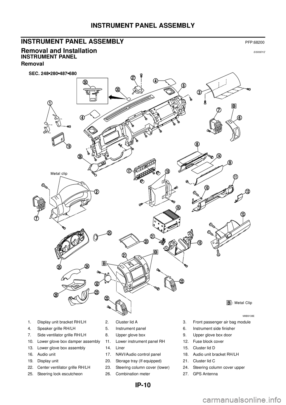
INSTRUMENT PANEL
Removal
1. Display unit bracket RH/LH 2. Cluster lid A 3. Front passenger air bag module
4. Speaker grille RH/LH 5. Instrument panel 6. Instrument side finisher
7. Side ventilator grille RH/LH 8. Upper glove box 9. Upper glove box door
10. Lower glove box damper assembly 11. Lower instrument panel RH 12. Fuse block cover
13. Lower glove box assembly 14. Liner 15. Cluster lid D
16. Audio unit 17. NAVI/Audio control panel 18. Audio unit bracket RH/LH
19. Display unit 20. Storage tray (If equipped) 21. Cluster lid C
22. Center ventilator grille RH/LH 23. Steering column cover (lower) 24. Steering column cover upper
25. Steering lock escutcheon 26. Combination meter 27. GPS Antenna
MIIB9138E
Page 1774 of 3171
INSTRUMENT PANEL ASSEMBLY
IP-15
C
D
E
F
G
H
J
K
L
MA
B
IP
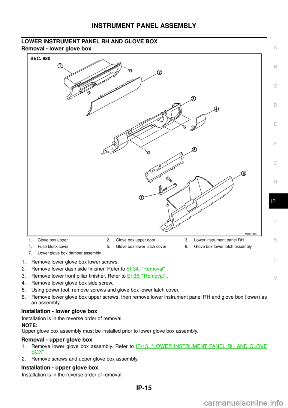
LOWER INSTRUMENT PANEL RH AND GLOVE BOX
Removal - lower glove box
1. Remove lower glove box lower screws.
2. Remove lower dash side finisher. Refer toEI-34, "
Removal".
3. Remove lower front pillar finisher. Refer toEI-35, "
Removal".
4. Remove lower glove box side screw.
5. Using power tool, remove screws and glove box lower latch cover.
6. Remove lower glove box upper screws, then remove lower instrument panel RH and glove box (lower) as
an assembly.
Installation - lower glove box
Installation is in the reverse order of removal.
NOTE:
Upper glove box assembly must be installed prior to lower glove box assembly.
Removal - upper glove box
1. Remove lower glove box assembly. Refer toIP-15, "LOWER INSTRUMENT PANEL RH AND GLOVE
BOX".
2. Remove screws and upper glove box assembly.
Installation - upper glove box
Installation is in the reverse order of removal.
1. Glove box upper 2. Glove box upper door 3. Lower instrument panel RH
4. Fuse block cover 5. Glove box lower latch cover 6. Glove box lower latch assembly
7. Lower glove box damper assembly
MIIB9141E
Page 1782 of 3171
![NISSAN NAVARA 2005 Repair Workshop Manual TROUBLE DIAGNOSES WORK FLOW
LAN-5
[CAN]
C
D
E
F
G
H
I
J
L
MA
B
LAN
TROUBLE DIAGNOSES WORK FLOWPFP:00004
When Displaying CAN Communication System ErrorsEKS00LBH
WHEN A MALFUNCTION IS DETECTED BY CAN CO NISSAN NAVARA 2005 Repair Workshop Manual TROUBLE DIAGNOSES WORK FLOW
LAN-5
[CAN]
C
D
E
F
G
H
I
J
L
MA
B
LAN
TROUBLE DIAGNOSES WORK FLOWPFP:00004
When Displaying CAN Communication System ErrorsEKS00LBH
WHEN A MALFUNCTION IS DETECTED BY CAN CO](/manual-img/5/57362/w960_57362-1781.png)
TROUBLE DIAGNOSES WORK FLOW
LAN-5
[CAN]
C
D
E
F
G
H
I
J
L
MA
B
LAN
TROUBLE DIAGNOSES WORK FLOWPFP:00004
When Displaying CAN Communication System ErrorsEKS00LBH
WHEN A MALFUNCTION IS DETECTED BY CAN COMMUNICATION SYSTEM
lCAN communication line is open. (CAN H, CAN L, or both)
lCAN communication line is shorted. (Ground, between CAN lines, or other harnesses)
lThe areas related to CAN communication of unit is malfunctioning.
WHEN A MALFUNCTION IS DETECTED EXCEPT CAN COMMUNICATION SYSTEM
lRemoval and installation of parts : When the units that perform CAN communication or the sensors
related to CAN communication are removed and installed, malfunction may be detected (or DTC other
than CAN communication may be detected).
lFuse blown out (removed): CAN communication of the unit may be stopped at such time.
lLow voltage : If the voltage decreases because of battery discharge when IGN is ON, malfunction may be
detected by self-diagnosis according to the units.
Page 2081 of 3171
![NISSAN NAVARA 2005 Repair Workshop Manual LAN-304
[CAN]
TROUBLE DIAGNOSIS FOR SYSTEM
3.CHECK HARNESS FOR SHORT CIRCUIT
Check continuity between data link connector M45 terminals 6, 14
and ground.
OK or NG
OK >> GO TO 4.
NG >>
lRepair harness. NISSAN NAVARA 2005 Repair Workshop Manual LAN-304
[CAN]
TROUBLE DIAGNOSIS FOR SYSTEM
3.CHECK HARNESS FOR SHORT CIRCUIT
Check continuity between data link connector M45 terminals 6, 14
and ground.
OK or NG
OK >> GO TO 4.
NG >>
lRepair harness.](/manual-img/5/57362/w960_57362-2080.png)
LAN-304
[CAN]
TROUBLE DIAGNOSIS FOR SYSTEM
3.CHECK HARNESS FOR SHORT CIRCUIT
Check continuity between data link connector M45 terminals 6, 14
and ground.
OK or NG
OK >> GO TO 4.
NG >>
lRepair harness.
lChange harness if shielded lines are used for the har-
ness.
4.ECM AND IPDM E/R INTERNAL CIRCUIT INSPECTION
1. Remove ECM and IPDM E/R from vehicle.
2. Check resistance between ECM terminals.
3. Check resistance between IPDM E/R terminals.
OK or NG
OK >> GO TO 5.
NG >> Replace ECM and/or IPDM E/R.
5.CHECK SYMPTOM
1. Fill in described symptoms on the column “Symptom” in the check sheet.
2. Connect all connectors, and then make sure that the symptom is reproduced.
OK or NG
OK >> GO TO 6.
NG >> Refer toLAN-13, "
Example of Filling in Check Sheet When Initial Conditions Are Not Reproduced"
.
6.UNIT REPRODUCIBILITY INSPECTION
Perform the following procedure for each unit on the CAN network, and then perform reproducibility test.
1. Turn ignition switch OFF.
2. Disconnect the battery cable from the negative terminal.
3. Disconnect the unit connector.
4. Connect the battery cable to the negative terminal.
5. Make sure that the symptom filled in the “Symptom” of the check sheet is reproduced. (Do not confuse it
with the symptom related to removed unit.)
6. Make sure that the same symptom is reproduced.
Inspection results
Reproduced>>Install removed unit, and then check the other unit.
Not reproduced>>Replace removed unit.
IPDM E/R Ignition Relay Circuit InspectionEKS00O5C
Check the following. If no malfunction is found, replace the IPDM E/R.
lIPDM E/R power supply circuit. Refer toPG-24, "Check IPDM E/R Power Supply and Ground Circuit". 6 – Ground : Continuity should not exist.
14 – Ground : Continuity should not exist.
PKIA9872E
Terminal Resistance (Approx.)
95 87 108 – 132W
Terminal Resistance (Approx.)
39 40 108 – 132W
LKIA0037E
Page 2088 of 3171
HEADLAMP -CONVENTIONAL TYPE-
LT-5
C
D
E
F
G
H
I
J
L
MA
B
LT
HEADLAMP -CONVENTIONAL TYPE-PFP:26010
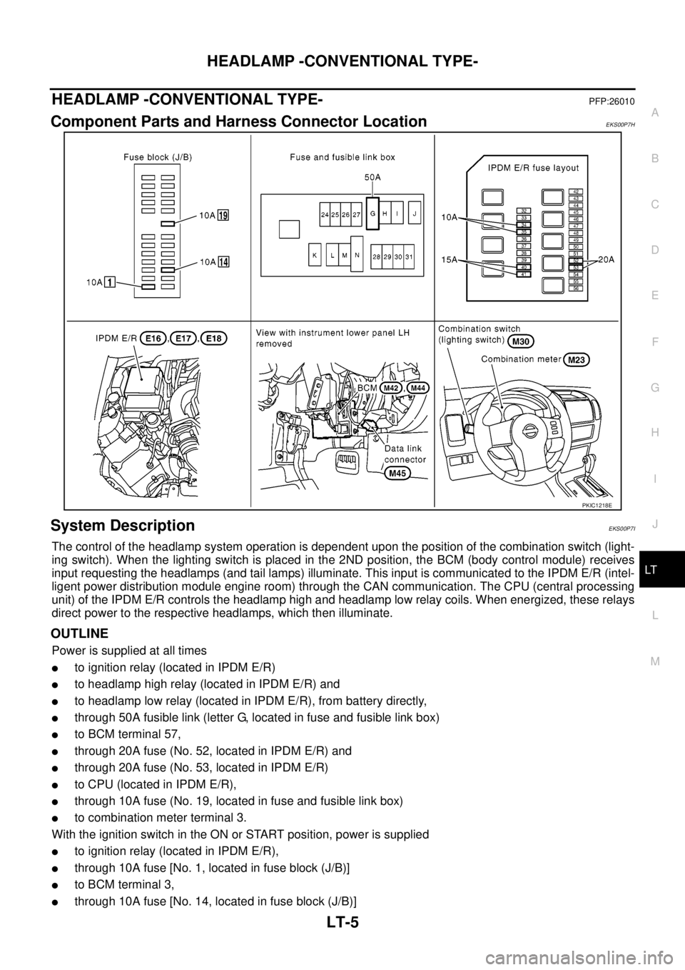
Component Parts and Harness Connector LocationEKS00P7H
System DescriptionEKS00P7I
The control of the headlamp system operation is dependent upon the position of the combination switch (light-
ing switch). When the lighting switch is placed in the 2ND position, the BCM (body control module) receives
input requesting the headlamps (and tail lamps) illuminate. This input is communicated to the IPDM E/R (intel-
ligent power distribution module engine room) through the CAN communication. The CPU (central processing
unit) of the IPDM E/R controls the headlamp high and headlamp low relay coils. When energized, these relays
direct power to the respective headlamps, which then illuminate.
OUTLINE
Power is supplied at all times
lto ignition relay (located in IPDM E/R)
lto headlamp high relay (located in IPDM E/R) and
lto headlamp low relay (located in IPDM E/R), from battery directly,
lthrough 50A fusible link (letter G, located in fuse and fusible link box)
lto BCM terminal 57,
lthrough 20A fuse (No. 52, located in IPDM E/R) and
lthrough 20A fuse (No. 53, located in IPDM E/R)
lto CPU (located in IPDM E/R),
lthrough 10A fuse (No. 19, located in fuse and fusible link box)
lto combination meter terminal 3.
With the ignition switch in the ON or START position, power is supplied
lto ignition relay (located in IPDM E/R),
lthrough 10A fuse [No. 1, located in fuse block (J/B)]
lto BCM terminal 3,
lthrough 10A fuse [No. 14, located in fuse block (J/B)]
PKIC1218E
Page 2089 of 3171
LT-6
HEADLAMP -CONVENTIONAL TYPE-
lto combination meter terminal 16.
Ground is supplied at all times
lto BCM terminal 55 and
lto combination meter terminal 23
lthrough grounds M21, M80 and M83,
lto IPDM E/R terminals 38 and 59
lthrough grounds E21, E41 and E61.
Low Beam Operation
With the lighting switch in 2ND position, the BCM receives input requesting the headlamps to illuminate. This
input is communicated to the IPDM E/R through the CAN communication. The CPU of the IPDM E/R controls
the headlamp low relay coil. When energized, this relay directs power
lthrough 15A fuse (No. 41, located in IPDM E/R)
lthrough IPDM E/R terminal 54
lto front combination lamp RH terminal 1,
lthrough 15A fuse (No. 40, located in IPDM E/R)
lthrough IPDM E/R terminal 52
lto front combination lamp LH terminal 1.
Ground is supplied
lto front combination lamp RH and LH terminals 3
lthrough grounds E21, E41 and E61.
With power and ground supplied, low beam headlamps illuminate.
High Beam Operation/Flash-to-Pass Operation
With the lighting switch in 2ND position and placed in HIGH or PASS position, the BCM receives input request-
ing the headlamp high beams to illuminate. This input is communicated to the IPDM E/R through the CAN
communication. The CPU of the IPDM E/R controls the headlamp high relay coil. When energized, this relay
directs power
lthrough 10A fuse (No. 34, located in IPDM E/R)
lthrough IPDM E/R terminal 56
lto front combination lamp RH terminal 2,
lthrough 10A fuse (No. 35, located in IPDM E/R)
lthrough IPDM E/R terminal 55
lto front combination lamp LH terminal 2.
Ground is supplied
lto front combination lamp RH and LH terminals 3
lthrough grounds E21, E41 and E61.
With power and ground supplied, the high beam headlamps illuminate.
Combination meter that received high beam request signal by BCM through the CAN communication makes a
high beam indicator lamp turn on in combination meter.
FRIENDLY LIGHTING FUNCTION
This function starts timer function of BCM by operating passing switch, and illuminates headlamps (LOW
beam) for a given length of time.
Headlamps (LOW beam) stay ON for a given length of time by operating passing switch when ignition switch is
OFF and lighting switch is OFF.
Headlamps (LOW beam) stays ON for two minutes at a maximum by operating passing switch repeatedly.
CONSULT-II is capable of setting a lighting time. Refer toLT- 1 6 , "
WORK SUPPORT".
CAN Communication System DescriptionEKS00P7J
Refer toLAN-23, "CAN COMMUNICATION".