Page 2462 of 3171
TROUBLE DIAGNOSIS
MTC-75
C
D
E
F
G
H
I
K
L
MA
B
MTC
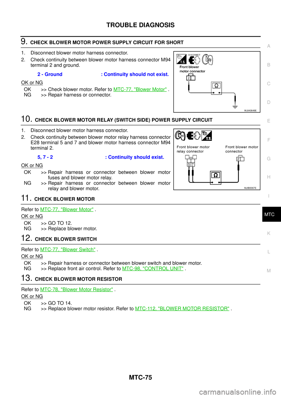
9.CHECK BLOWER MOTOR POWER SUPPLY CIRCUIT FOR SHORT
1. Disconnect blower motor harness connector.
2. Check continuity between blower motor harness connector M94
terminal 2 and ground.
OK or NG
OK >> Check blower motor. Refer toMTC-77, "Blower Motor".
NG >> Repair harness or connector.
10.CHECK BLOWER MOTOR RELAY (SWITCH SIDE) POWER SUPPLY CIRCUIT
1. Disconnect blower motor harness connector.
2. Check continuity between blower motor relay harness connector
E28 terminal 5 and 7 and blower motor harness connector M94
terminal 2.
OK or NG
OK >> Repair harness or connector between blower motor
fuses and blower motor relay.
NG >> Repair harness or connector between blower motor
relay and blower motor.
11 .CHECK BLOWER MOTOR
Refer toMTC-77, "
Blower Motor".
OK or NG
OK >> GO TO 12.
NG >> Replace blower motor.
12.CHECK BLOWER SWITCH
Refer toMTC-77, "
Blower Switch".
OK or NG
OK >> Repair harness or connector between blower switch and blower motor.
NG >> Replace front air control. Refer toMTC-98, "
CONTROL UNIT".
13.CHECK BLOWER MOTOR RESISTOR
Refer toMTC-78, "
Blower Motor Resistor".
OK or NG
OK >> GO TO 14.
NG >> Replace blower motor resistor. Refer toMTC-112, "
BLOWER MOTOR RESISTOR". 2 - Ground : Continuity should not exist.
WJIA0649E
5, 7 - 2 : Continuity should exist.
MJIB0067E
Page 2468 of 3171
TROUBLE DIAGNOSIS
MTC-81
C
D
E
F
G
H
I
K
L
MA
B
MTC
2.PERFORM AUTO ACTIVE TEST
Refer toPG-19, "
Auto Active Test".
Does magnet clutch operate?
YES or NO
YES >>lWITH CONSULT-II
GO TO 5.
lWITHOUT CONSULT-II
GO TO 6.
NO >> Check 10A fuse (No. 42, located in IPDM E/R), and GO TO 3.
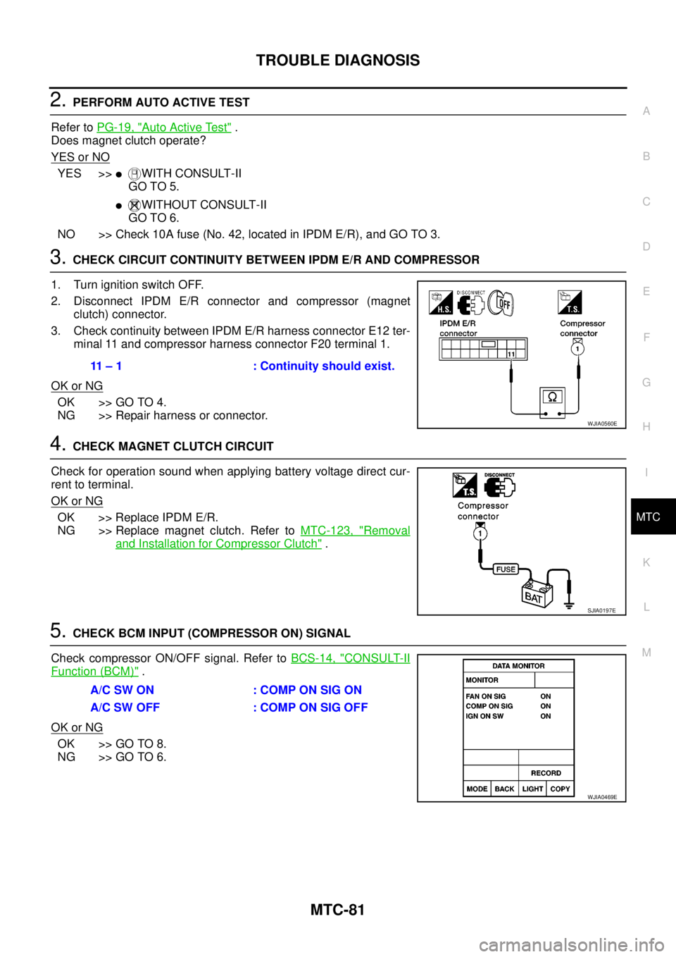
3.CHECK CIRCUIT CONTINUITY BETWEEN IPDM E/R AND COMPRESSOR
1. Turn ignition switch OFF.
2. Disconnect IPDM E/R connector and compressor (magnet
clutch) connector.
3. Check continuity between IPDM E/R harness connector E12 ter-
minal 11 and compressor harness connector F20 terminal 1.
OK or NG
OK >> GO TO 4.
NG >> Repair harness or connector.
4.CHECK MAGNET CLUTCH CIRCUIT
Check for operation sound when applying battery voltage direct cur-
rent to terminal.
OK or NG
OK >> Replace IPDM E/R.
NG >> Replace magnet clutch. Refer toMTC-123, "
Removal
and Installation for Compressor Clutch".
5.CHECK BCM INPUT (COMPRESSOR ON) SIGNAL
Check compressor ON/OFF signal. Refer toBCS-14, "
CONSULT-II
Function (BCM)".
OK or NG
OK >> GO TO 8.
NG >> GO TO 6.
11 – 1 : Continuity should exist.
WJIA0560E
SJIA0197E
A/C SW ON : COMP ON SIG ON
A/CSWOFF :COMPONSIGOFF
WJIA0469E
Page 2492 of 3171
HEATER & COOLING UNIT ASSEMBLY
MTC-105
C
D
E
F
G
H
I
K
L
MA
B
MTC
Removal and InstallationEJS005GY
REMOVAL
1. Discharge the refrigerant from the A/C system. Refer toMTC-118, "Discharging Refrigerant".
2. Drain the coolant from the engine cooling system. Refer toCO-8, "
DRAINING ENGINE COOLANT".
3. Remove the cowl top extension. Refer toEI-20, "
Removal and Installation".
4. Remove the exhaust system. Refer toEX-3, "
Removal and Installation".
5. Disconnect the heater hoses from the heater core.
6. Disconnect the high/low pressure pipes from the expansion valve.
7. Move the two front seats to the rearmost position on the seat track.
8. Remove the instrument panel and console panel. Refer toIP-10, "
Removal and Installation".
9. Remove the steering column. Refer toPS-11, "
Removal and Installation".
10. Disconnect the instrument panel wire harness at the RH and LH in-line connector brackets, and the fuse
block (J/B) electrical connectors. Refer toPG-38, "
Harness Layout".
11. Disconnect the steering member from each side of the vehicle body.
12. Remove the heater and cooling unit assembly with it attached to the steering member, from the vehicle.
CAUTION:
Use care not to damage the seats and interior trim panels when removing the heater and cooling
unit assembly with it attached to the steering member.
13. Remove the heater and cooling unit assembly from the steering member.
INSTALLATION
Installation is in the reverse order of removal.
CAUTION:
lReplace the O-ring of the low-pressure pipe and high-pressure pipe with a new one, and apply
compressor oil to it when installing it.
lAfter charging the refrigerant, check for leaks.
NOTE:
lFill the engine cooling system with the specified coolant mixture. Refer toCO-8, "REFILLING ENGINE
COOLANT".
lRecharge the A/C system. Refer toMTC-118, "Evacuating System and Charging Refrigerant".
Page 2531 of 3171

PG-2
REAR DOOR LH HARNESS/KING CAB MOD-
ELS ...................................................................... 66
REAR DOOR RH HARNESS/KING CAB MOD-
ELS ...................................................................... 66
TAIL HARNESS ................................................... 67
Wiring Diagram Codes (Cell Codes) ....................... 68
ELECTRICAL UNITS LOCATION ............................. 71
Electrical Units Location ......................................... 71
ENGINE COMPARTMENT .................................. 71
PASSENGER COMPARTMENT .......................... 72
Fuse ........................................................................ 74
Fusible Link ............................................................ 74
Circuit Breaker (Built Into BCM) ............................. 74
HARNESS CONNECTOR ......................................... 75
Description .............................................................. 75
HARNESS CONNECTOR (TAB-LOCKING
TYPE) .................................................................. 75
HARNESS CONNECTOR (SLIDE-LOCKINGTYPE) .................................................................. 76
HARNESS CONNECTOR (DIRECT-CONNECT
SRS COMPONENT TYPE) .................................. 77
ELECTRICAL UNITS ................................................ 78
Terminal Arrangement ............................................. 78
STANDARDIZED RELAY .......................................... 79
Description .............................................................. 79
NORMAL OPEN, NORMAL CLOSED AND
MIXED TYPE RELAYS ........................................ 79
TYPE OF STANDARDIZED RELAYS .................. 79
SUPER MULTIPLE JUNCTION (SMJ) ...................... 81
Terminal Arrangement ............................................. 81
FUSE BLOCK - JUNCTION BOX (J/B) .................... 83
Terminal Arrangement ............................................. 83
FUSE AND FUSIBLE LINK BOX .............................. 84
Terminal Arrangement ............................................. 84
FUSE AND RELAY BOX ........................................... 85
Terminal Arrangement ............................................. 85
Page 2543 of 3171

PG-14
IPDM E/R (INTELLIGENT POWER DISTRIBUTION MODULE ENGINE ROOM)
IPDM E/R (INTELLIGENT POWER DISTRIBUTION MODULE ENGINE ROOM)
PFP:284B7
System DescriptionEKS00PA8
lIPDM E/R (Intelligent Power Distribution Module Engine Room) integrates the relay box and fuse block
which were originally placed in engine compartment. It controls integrated relays via IPDM E/R control cir-
cuits.
lIPDM E/R-integrated control circuits perform ON-OFF operation of relays, CAN communication control,
etc.
lIt controls operation of each electrical component via ECM, BCM and CAN communication lines.
CAUTION:
None of the IPDM E/R integrated relays can be removed.
SYSTEMS CONTROLLED BY IPDM E/R
IPDM E/R receives a request signal from each Control unit with CAN communication. It controls each system.
CAN COMMUNICATION LINE CONTROL
With CAN communication, by connecting each control unit using two communication lines (CAN L-line, CAN
H-line), it is possible to transmit a maximum amount of information with minimum wiring. Each control unit can
transmit and receive data, and reads necessary information only.
1. Fail-safe control
lWhen CAN communication with other control units is impossible, IPDM E/R performs fail-safe control.
After CAN communication returns to normal operation, it also returns to normal control.
lOperation of control parts by IPDM E/R during fail-safe mode is as follows:
Control system Transmit control unit Control part
Lamp control BCM
lHead lamps (HI, LO)
lTail lamps, parking and license plate lamps
lFront fog lamps
Wiper control BCM Front wipers
Rear window defogger control BCM Rear window defogger
A/C compressor control ECM A/C compressor
Starter control TCM Starter motor
Cooling fan control ECM Cooling fan
Controlled system Fail-safe mode
Headlamps
lWith the ignition switch ON, the headlamp low is ON.
lWith the ignition switch OFF, the headlamp low is OFF.
Tail, parking and license plate lamps
lWith the ignition switch ON, the tail lamp is ON.
lWith the ignition switch OFF, the tail lamp is OFF.
Cooling fan
lWith the ignition switch ON, the cooling fan HI operates.
lWith the ignition switch OFF, the cooling fan stops.
Front wipersUntil the ignition switch is turned off, the front wiper LO and HI remains in the same status it
was in just before fail-safe control was initiated.
Rear window defogger Rear window defogger OFF
A/C compressor A/C compressor OFF
Front fog lamps Front fog lamp OFF
Page 2553 of 3171
PG-24
IPDM E/R (INTELLIGENT POWER DISTRIBUTION MODULE ENGINE ROOM)
Check IPDM E/R Power Supply and Ground Circuit
EKS00PAF
1.CHECK FUSES AND FUSIBLE LINK
Check for blown fuses and fusible link.
OK or NG
OK >> GO TO 2.
NG >> If fuse or fusible link is blown, be sure to eliminate cause of malfunction before installing new fuse
or fusible link.
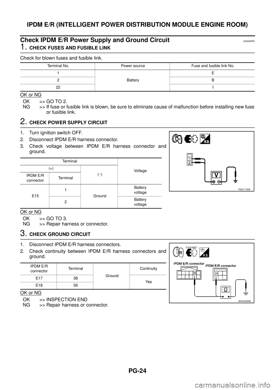
2.CHECK POWER SUPPLY CIRCUIT
1. Turn ignition switch OFF.
2. Disconnect IPDM E/R harness connector.
3. Check voltage between IPDM E/R harness connector and
ground.
OK or NG
OK >> GO TO 3.
NG >> Repair harness or connector.
3.CHECK GROUND CIRCUIT
1. Disconnect IPDM E/R harness connectors.
2. Check continuity between IPDM E/R harness connectors and
ground.
OK or NG
OK >> INSPECTION END
NG >> Repair harness or connector.
Terminal No. Power source Fuse and fusible link No.
1
BatteryE
2B
221
Te r m i n a l
Vo l ta g e (+)
(-)
IRDM E/R
connectorTerminal
E151
GroundBattery
voltage
2Battery
voltage
PKIC1722E
IPDM E/R
connectorTerminal
GroundContinuity
E17 38
Ye s
E18 59
WKIA3354E
Page 2603 of 3171
PG-74
ELECTRICAL UNITS LOCATION
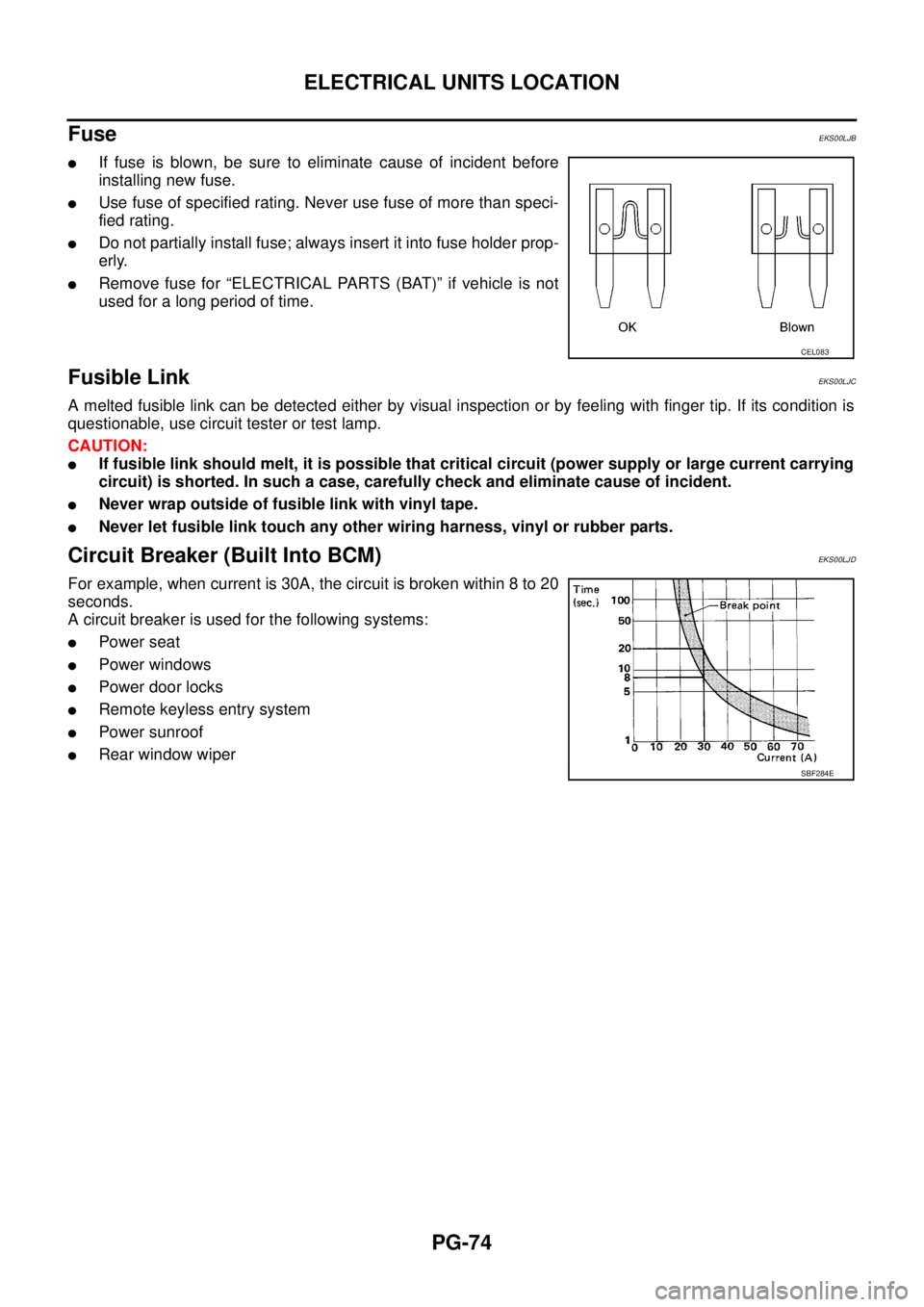
Fuse
EKS00LJB
lIf fuse is blown, be sure to eliminate cause of incident before
installing new fuse.
lUse fuse of specified rating. Never use fuse of more than speci-
fied rating.
lDo not partially install fuse; always insert it into fuse holder prop-
erly.
lRemove fuse for “ELECTRICAL PARTS (BAT)” if vehicle is not
used for a long period of time.
Fusible LinkEKS00LJC
A melted fusible link can be detected either by visual inspection or by feeling with finger tip. If its condition is
questionable, use circuit tester or test lamp.
CAUTION:
lIf fusible link should melt, it is possible that critical circuit (power supply or large current carrying
circuit) is shorted. In such a case, carefully check and eliminate cause of incident.
lNever wrap outside of fusible link with vinyl tape.
lNever let fusible link touch any other wiring harness, vinyl or rubber parts.
Circuit Breaker (Built Into BCM)EKS00LJD
For example, when current is 30A, the circuit is broken within 8 to 20
seconds.
A circuit breaker is used for the following systems:
lPower seat
lPower windows
lPowerdoorlocks
lRemote keyless entry system
lPower sunroof
lRear window wiper
CEL083
SBF284E
Page 2612 of 3171
FUSE BLOCK - JUNCTION BOX (J/B)
PG-83
C
D
E
F
G
H
I
J
L
MA
B
PG
FUSE BLOCK - JUNCTION BOX (J/B)PFP:24350
Terminal ArrangementEKS00LJI
MKWA3881E