2005 NISSAN NAVARA fuse
[x] Cancel search: fusePage 2860 of 3171

STARTING SYSTEM
SC-27
C
D
E
F
G
H
I
J
L
MA
B
SC
STARTING SYSTEMPFP:00011
System DescriptionEKS00MZJ
A/T MODELS
Power is supplied at all times:
lto starter motor terminal 1 and
lthrough 40A fusible link (letterJ, located in the fuse and fusible link box)
lto ignition switch terminal 1.
with the ignition switch in the START position, power is supplied:
lfrom ignition switch terminal 5
lto IPDM E/R terminal 21.
With the ignition switch in the ON or START position, power is supplied to IPDM E/R CPU, and
the selector lever in the P or N position, power is supplied:
lthrough A/T assembly terminal 9
lto IPDM E/R terminal 48.
Ground is supplied at all times:
lto IPDM E/R terminals 38 and 59
lfrom body grounds E21, E41 and E61.
Then the starter relay is turned ON.
The IPDM E/R starter relay is energized and power is supplied:
lfrom terminal 19 of IPDM E/R
lto terminal 2 of the starter motor.
The starter motor plunger closes and provides a closed circuit between the battery and the starter motor. The
starter motor is grounded to the cylinder block. With power and ground supplied, the starter motor operates.
M/T MODELS
Power is supplied at all times:
lto starter motor terminal 1 and
lthrough 40A fusible link (letterJ, located in the fuse and fusible link box)
lto ignition switch terminal 1.
with the ignition switch in the START position, power is supplied:
lfrom ignition switch terminal 5
lto IPDM E/R terminal 21.
With the start signal is input to IPDM E/R CPU, power is supplied:
lthrough IPDM E/R terminal 14
lto IPDM E/R terminal 48.
Ground is supplied at all times:
lto IPDM E/R terminals 38 and 59
lfrom body grounds E21, E41 and E61.
Then the starter relay is turned ON.
The IPDM E/R starter relay is energized and power is supplied:
lfrom terminal 19 of IPDM E/R
lto terminal 2 of the starter motor.
The starter motor plunger closes and provides a closed circuit between the battery and the starter motor. The
starter motor is grounded to the cylinder block. With power and ground supplied, the starter motor operates.
Page 2894 of 3171
FRONT SEAT
SE-23
C
D
E
F
G
H
J
K
L
MA
B
SE
Removal and InstallationEIS00C62
REMOVAL
When removing or installing the seat trim, handle it carefully to keep dirt out and avoid damage.
CAUTION:
lBefore removing the front seat, turn the ignition switch off, disconnect both battery cables and
wait at least 3 minutes.
lWhen checking the power seat circuit for continuity using a circuit tester, do not confuse its con-
nector with the side air bag module connector. Such an error may cause the air bag to deploy.
lDo not drop, tilt, or bump the side air bag module while installing the seat. Always handle it with
care.
lAfter front side air bag module inflates, front seatback assembly must be replaced.
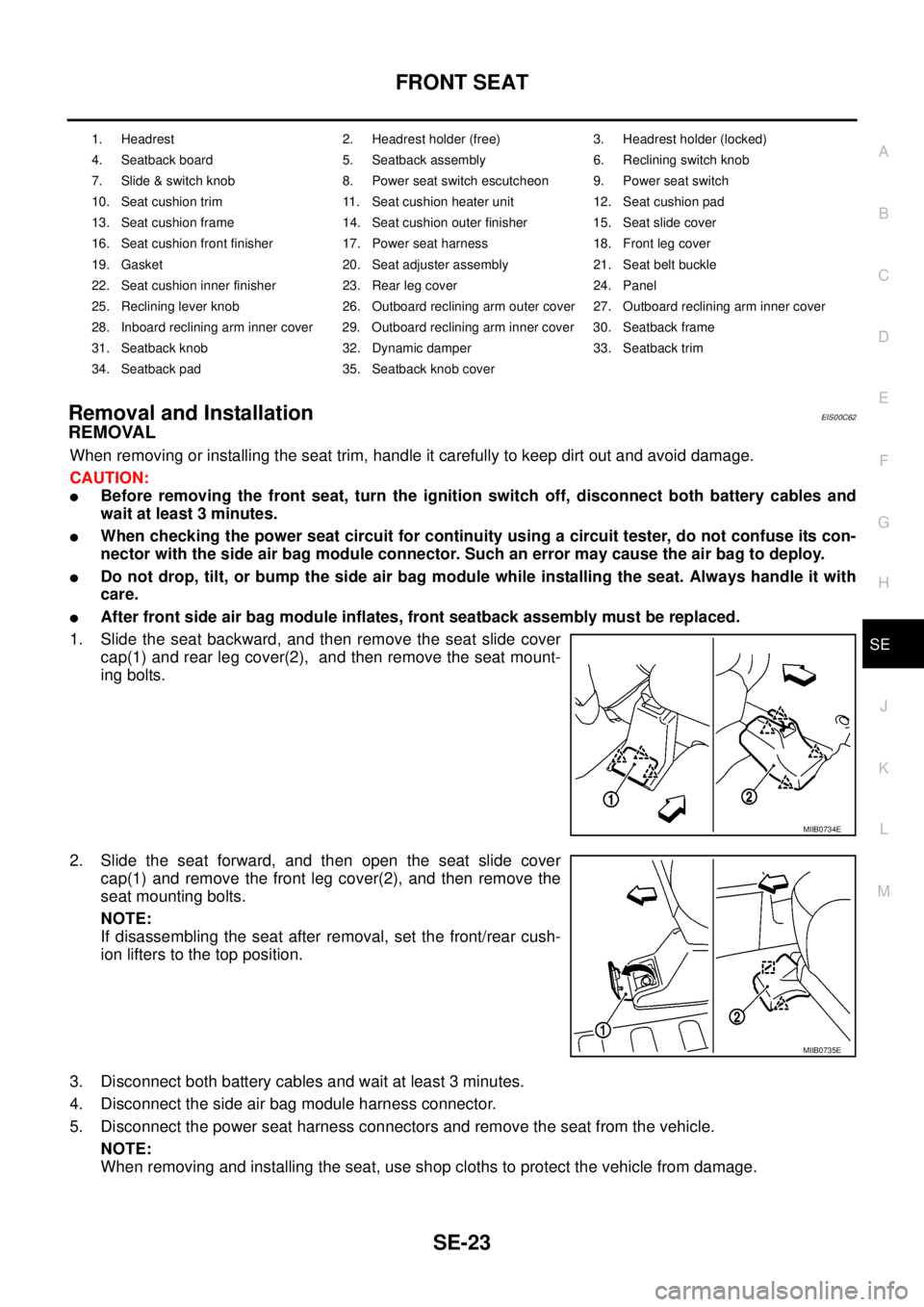
1. Slide the seat backward, and then remove the seat slide cover
cap(1) and rear leg cover(2), and then remove the seat mount-
ing bolts.
2. Slide the seat forward, and then open the seat slide cover
cap(1) and remove the front leg cover(2), and then remove the
seat mounting bolts.
NOTE:
If disassembling the seat after removal, set the front/rear cush-
ion lifters to the top position.
3. Disconnect both battery cables and wait at least 3 minutes.
4. Disconnect the side air bag module harness connector.
5. Disconnect the power seat harness connectors and remove the seat from the vehicle.
NOTE:
When removing and installing the seat, use shop cloths to protect the vehicle from damage.
1. Headrest 2. Headrest holder (free) 3. Headrest holder (locked)
4. Seatback board 5. Seatback assembly 6. Reclining switch knob
7. Slide & switch knob 8. Power seat switch escutcheon 9. Power seat switch
10. Seat cushion trim 11. Seat cushion heater unit 12. Seat cushion pad
13. Seat cushion frame 14. Seat cushion outer finisher 15. Seat slide cover
16. Seat cushion front finisher 17. Power seat harness 18. Front leg cover
19. Gasket 20. Seat adjuster assembly 21. Seat belt buckle
22. Seat cushion inner finisher 23. Rear leg cover 24. Panel
25. Reclining lever knob 26. Outboard reclining arm outer cover 27. Outboard reclining arm inner cover
28. Inboard reclining arm inner cover 29. Outboard reclining arm inner cover 30. Seatback frame
31. Seatback knob 32. Dynamic damper 33. Seatback trim
34. Seatback pad 35. Seatback knob cover
MIIB0734E
MIIB0735E
Page 2918 of 3171
TROUBLE DIAGNOSIS
SRS-9
C
D
E
F
G
I
J
K
L
MA
B
SRS
TROUBLE DIAGNOSISPFP:00004
Trouble Diagnosis IntroductionEHS001XG
CAUTION:
lDo not use electrical test equipment on any circuit related to the SRS unless instructed to do so in
this Service Manual. SRS wiring harnesses can be identified by yellow and/or orange harness con-
nectors.
lDo not attempt to repair, splice or modify SRS wiring harnesses. If a harness is damaged, replace
it with a new one.
lKeep ground connections clean.
DIAGNOSIS FUNCTION
The SRS self-diagnosis results can be read by using “AIR BAG” warning lamp and/or CONSULT-II.
The User mode is exclusively prepared for the customer (driver). This mode warns the driver of a system mal-
function through the operation of the “AIR BAG” warning lamp.
The Diagnosis mode allows the technician to locate and inspect the malfunctioning part.
The mode applications for the “AIR BAG” warning lamp and CONSULT-II are as follows:
HOW TO PERFORM TROUBLE DIAGNOSES FOR QUICK AND ACCURATE REPAIR
A good understanding of the malfunction conditions can make troubleshooting faster and more accurate.
In general, each customer feels differently about a malfunction. It is important to fully understand the symp-
toms or conditions for a customer complaint.
Information From Customer
WHAT - Vehicle model
WHEN - Date, Frequencies
WHERE - Road conditions
HOW - Operating conditions, Symptoms
Preliminary Check
Check that the following parts are in good order.
lBattery (Refer toSC-5, "How to Handle Battery".)
lFuse (Refer toSRS-13, "Wiring Diagram–SRS–".)
lSystem component-to-harness connections
User mode Diagnosis mode Display type
“AIR BAG” warning lamp X X ON-OFF operation
CONSULT-II — X Monitoring
Page 2943 of 3171
SRS-34
TROUBLE DIAGNOSIS
Trouble Diagnosis: “AIR BAG” Warning Lamp Does Not Turn OFF
EHS001XQ
DIAGNOSTIC PROCEDURE 7
1.CHECK CONDITION OF AIR BAG MODULES
Inspect for any deployed air bag modules or seat belt pre-tensioners.
Are any air bag modules or seat belt pre-tensioners deployed?
Yes >> Refer toSRS-56, "COLLISION DIAGNOSIS".
No >> GO TO 2.
2.CHECK THE AIR BAG FUSE
Check 10A fuse [No. 13, located in the fuse block (J/B)].
Refer toPG-4, "
POWER SUPPLY ROUTING CIRCUIT".
OK or NG
OK >> GO TO 4.
NG >> GO TO 3.
3.CHECK AIR BAG FUSE AGAIN
Replace 10A fuse [No. 13, located in the fuse block (J/B)] and turn ignition switch ON.
Does the fuse blow again?
Yes >> Repair or replace main harness.
No >> Inspection End.
4.CHECK AIR BAG DIAGNOSIS SENSOR UNIT
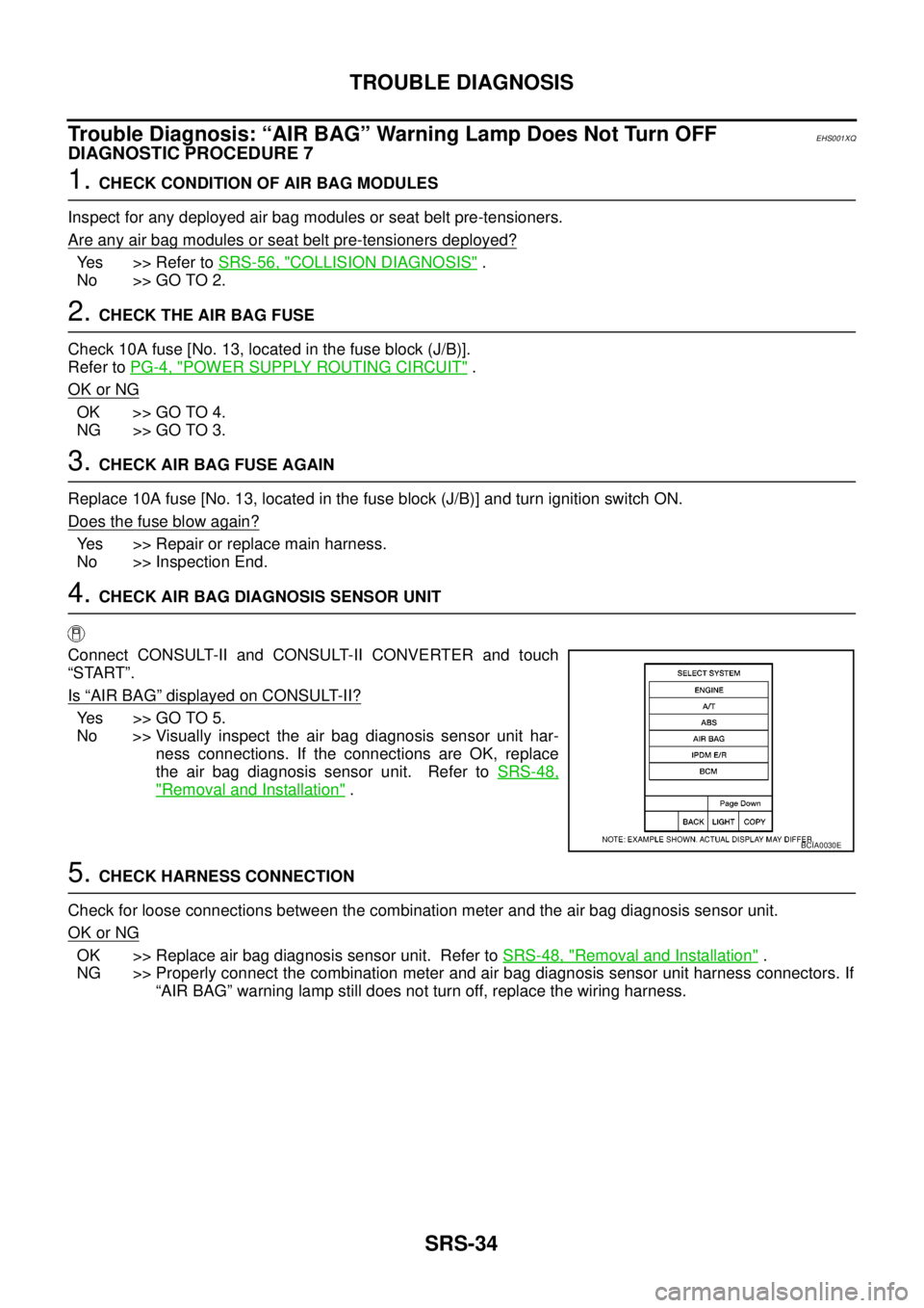
Connect CONSULT-II and CONSULT-II CONVERTER and touch
“START”.
Is
“AIR BAG”displayed on CONSULT-II?
Yes >>GOTO5.
No >> Visually inspect the air bag diagnosis sensor unit har-
ness connections. If the connections are OK, replace
the air bag diagnosis sensor unit. Refer toSRS-48,
"Removal and Installation".
5.CHECK HARNESS CONNECTION
Check for loose connections between the combination meter and the air bag diagnosis sensor unit.
OK or NG
OK >> Replace air bag diagnosis sensor unit. Refer toSRS-48, "Removal and Installation".
NG >> Properly connect the combination meter and air bag diagnosis sensor unit harness connectors. If
“AIR BAG” warning lamp still does not turn off, replace the wiring harness.
BCIA0030E
Page 2944 of 3171
TROUBLE DIAGNOSIS
SRS-35
C
D
E
F
G
I
J
K
L
MA
B
SRS
Trouble Diagnosis: “AIR BAG” Warning Lamp Does Not Turn ONEHS001XR
DIAGNOSTIC PROCEDURE 8
1.CHECK METER FUSE
Check the 10A fuse [No. 14, located in the fuse block (J/B)].
Refer toPG-4, "
POWER SUPPLY ROUTING CIRCUIT".
OK or NG
OK >> GO TO 3.
NG >> GO TO 2.
2.CHECK METER FUSE AGAIN
Replace 10A fuse [No. 14, located in the fuse block (J/B)] and turn ignition switch ON.
Does the fuse blow again?
Yes >> Repair or replace the related harness.
No >> Inspection End.
3.CHECK HARNESS CONNECTION BETWEEN AIR BAG DIAGNOSIS SENSOR UNIT AND COMBINA-
TION METER
Disconnect the air bag diagnosis sensor unit harness connectors and turn ignition switch ON.
Does
“AIR BAG”warninglampturnON?
Yes >> Replace the air bag diagnosis sensor unit. Refer toSRS-48, "Removal and Installation".
No >> Check the combination meter power supply circuits and ground circuits. If OK, replace combina-
tion meter.
Page 3020 of 3171
TROUBLE DIAGNOSIS FOR SYSTEM
TF-53
C
E
F
G
H
I
J
K
L
MA
B
TF
DIAGNOSTIC PROCEDURE
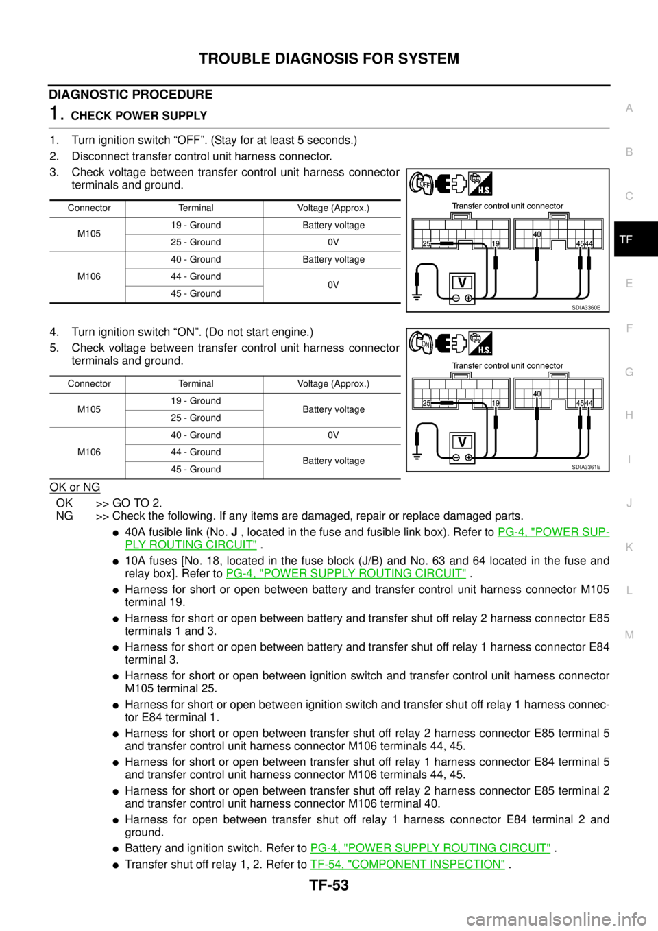
1.CHECK POWER SUPPLY
1. Turn ignition switch “OFF”. (Stay for at least 5 seconds.)
2. Disconnect transfer control unit harness connector.
3. Check voltage between transfer control unit harness connector
terminals and ground.
4. Turn ignition switch “ON”. (Do not start engine.)
5. Check voltage between transfer control unit harness connector
terminals and ground.
OK or NG
OK >> GO TO 2.
NG >> Check the following. If any items are damaged, repair or replace damaged parts.
l40A fusible link (No.J, located in the fuse and fusible link box). Refer toPG-4, "POWER SUP-
PLY ROUTING CIRCUIT".
l10A fuses [No. 18, located in the fuse block (J/B) and No. 63 and 64 located in the fuse and
relay box]. Refer toPG-4, "
POWER SUPPLY ROUTING CIRCUIT".
lHarness for short or open between battery and transfer control unit harness connector M105
terminal 19.
lHarness for short or open between battery and transfer shut off relay 2 harness connector E85
terminals 1 and 3.
lHarness for short or open between battery and transfer shut off relay 1 harness connector E84
terminal 3.
lHarness for short or open between ignition switch and transfer control unit harness connector
M105 terminal 25.
lHarness for short or open between ignition switch and transfer shut off relay 1 harness connec-
tor E84 terminal 1.
lHarness for short or open between transfer shut off relay 2 harness connector E85 terminal 5
and transfer control unit harness connector M106 terminals 44, 45.
lHarness for short or open between transfer shut off relay 1 harness connector E84 terminal 5
and transfer control unit harness connector M106 terminals 44, 45.
lHarness for short or open between transfer shut off relay 2 harness connector E85 terminal 2
and transfer control unit harness connector M106 terminal 40.
lHarness for open between transfer shut off relay 1 harness connector E84 terminal 2 and
ground.
lBattery and ignition switch. Refer toPG-4, "POWER SUPPLY ROUTING CIRCUIT".
lTransfer shut off relay 1, 2. Refer toTF-54, "COMPONENT INSPECTION".
Connector Terminal Voltage (Approx.)
M10519 - Ground Battery voltage
25 - Ground 0V
M10640 - Ground Battery voltage
44 - Ground
0V
45 - Ground
SDIA3360E
Connector Terminal Voltage (Approx.)
M10519 - Ground
Battery voltage
25 - Ground
M10640 - Ground 0V
44 - Ground
Battery voltage
45 - Ground
SDIA3361E
Page 3028 of 3171
TROUBLE DIAGNOSIS FOR SYSTEM
TF-61
C
E
F
G
H
I
J
K
L
MA
B
TF
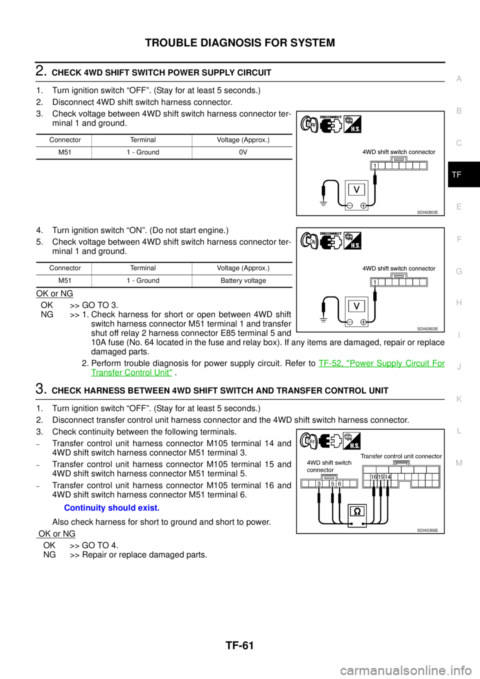
2.CHECK 4WD SHIFT SWITCH POWER SUPPLY CIRCUIT
1. Turn ignition switch “OFF”. (Stay for at least 5 seconds.)
2. Disconnect 4WD shift switch harness connector.
3. Check voltage between 4WD shift switch harness connector ter-
minal 1 and ground.
4. Turn ignition switch “ON”. (Do not start engine.)
5. Check voltage between 4WD shift switch harness connector ter-
minal 1 and ground.
OK or NG
OK >> GO TO 3.
NG >> 1. Check harness for short or open between 4WD shift
switch harness connector M51 terminal 1 and transfer
shut off relay 2 harness connector E85 terminal 5 and
10A fuse (No. 64 located in the fuse and relay box). If any items are damaged, repair or replace
damaged parts.
2. Perform trouble diagnosis for power supply circuit. Refer toTF-52, "
Power Supply Circuit For
Transfer Control Unit".
3.CHECK HARNESS BETWEEN 4WD SHIFT SWITCH AND TRANSFER CONTROL UNIT
1. Turn ignition switch “OFF”. (Stay for at least 5 seconds.)
2. Disconnect transfer control unit harness connector and the 4WD shift switch harness connector.
3. Check continuity between the following terminals.
–Transfer control unit harness connector M105 terminal 14 and
4WD shift switch harness connector M51 terminal 3.
–Transfer control unit harness connector M105 terminal 15 and
4WD shift switch harness connector M51 terminal 5.
–Transfer control unit harness connector M105 terminal 16 and
4WD shift switch harness connector M51 terminal 6.
Also check harness for short to ground and short to power.
OK or NG
OK >> GO TO 4.
NG >> Repair or replace damaged parts.
Connector Terminal Voltage (Approx.)
M51 1 - Ground 0V
SDIA2803E
Connector Terminal Voltage (Approx.)
M51 1 - Ground Battery voltage
SDIA2802E
Continuity should exist.
SDIA3366E
Page 3037 of 3171
TF-70
TROUBLE DIAGNOSIS FOR SYSTEM
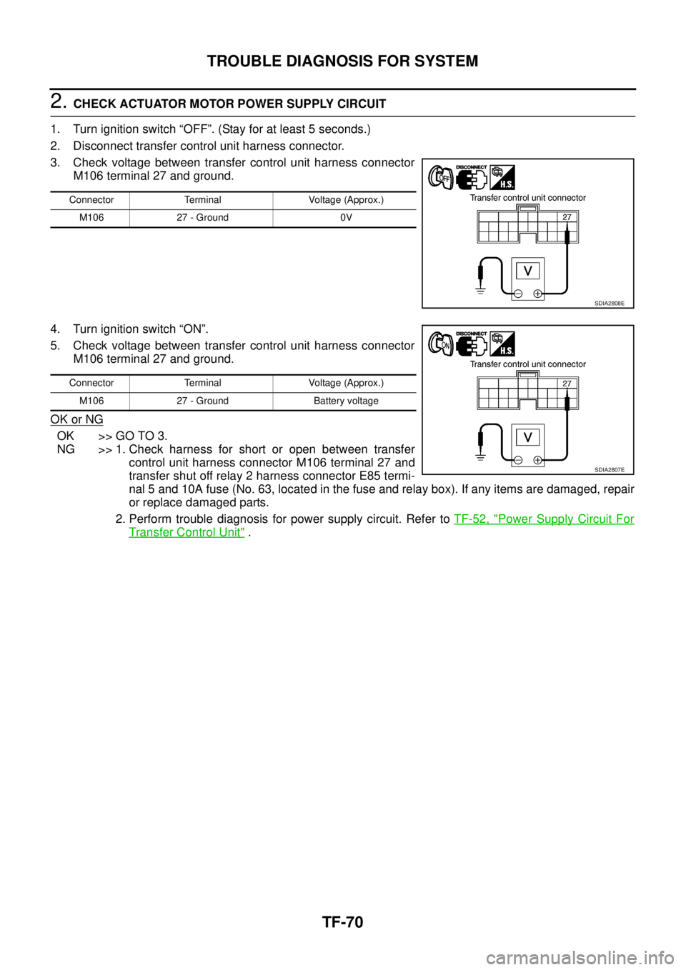
2.CHECK ACTUATOR MOTOR POWER SUPPLY CIRCUIT
1. Turn ignition switch “OFF”. (Stay for at least 5 seconds.)
2. Disconnect transfer control unit harness connector.
3. Check voltage between transfer control unit harness connector
M106 terminal 27 and ground.
4. Turn ignition switch “ON”.
5. Check voltage between transfer control unit harness connector
M106 terminal 27 and ground.
OK or NG
OK >> GO TO 3.
NG >> 1. Check harness for short or open between transfer
control unit harness connector M106 terminal 27 and
transfer shut off relay 2 harness connector E85 termi-
nal 5 and 10A fuse (No. 63, located in the fuse and relay box). If any items are damaged, repair
or replace damaged parts.
2. Perform trouble diagnosis for power supply circuit. Refer toTF-52, "
Power Supply Circuit For
Transfer Control Unit".
Connector Terminal Voltage (Approx.)
M106 27 - Ground 0V
SDIA2808E
Connector Terminal Voltage (Approx.)
M106 27 - Ground Battery voltage
SDIA2807E