2005 NISSAN NAVARA fuse
[x] Cancel search: fusePage 2693 of 3171

RF-16
SUNROOF
Work Flow
EIS00D52
1. Check the symptom and customer's requests.
2. Understand the outline of system. Refer toRF-11, "
System Description".
3. According to the trouble diagnosis chart, repair or replace the cause of the malfunction. Refer toRF-16,
"Trouble Diagnosis Symptom Chart".
4. Does sunroof system operate normally? If Yes, GO TO 5. If No, GO TO 3.
5. INSPECTION END.
Trouble Diagnosis Symptom ChartEIS00D53
BCM Power Supply and Ground Circuit CheckEIS00D54
1.FUSE INSPECTION
Check the following.
l50A fusible link (letterG, located in the fuse and fusible link box)
l10A fuse [No. 1, located in the fuse block (J/B)]
l10A fuse [No.21 located in the fuse block (J/B)]
NOTE:
Refer toRF-10, "
Component Parts and Harness Connector Location".
OK or NG
OK >> GO TO 2.
NG >> If fuse is blown, be sure to eliminate cause of malfunction before installing new fuse, refer toPG-
4, "POWER SUPPLY ROUTING CIRCUIT".
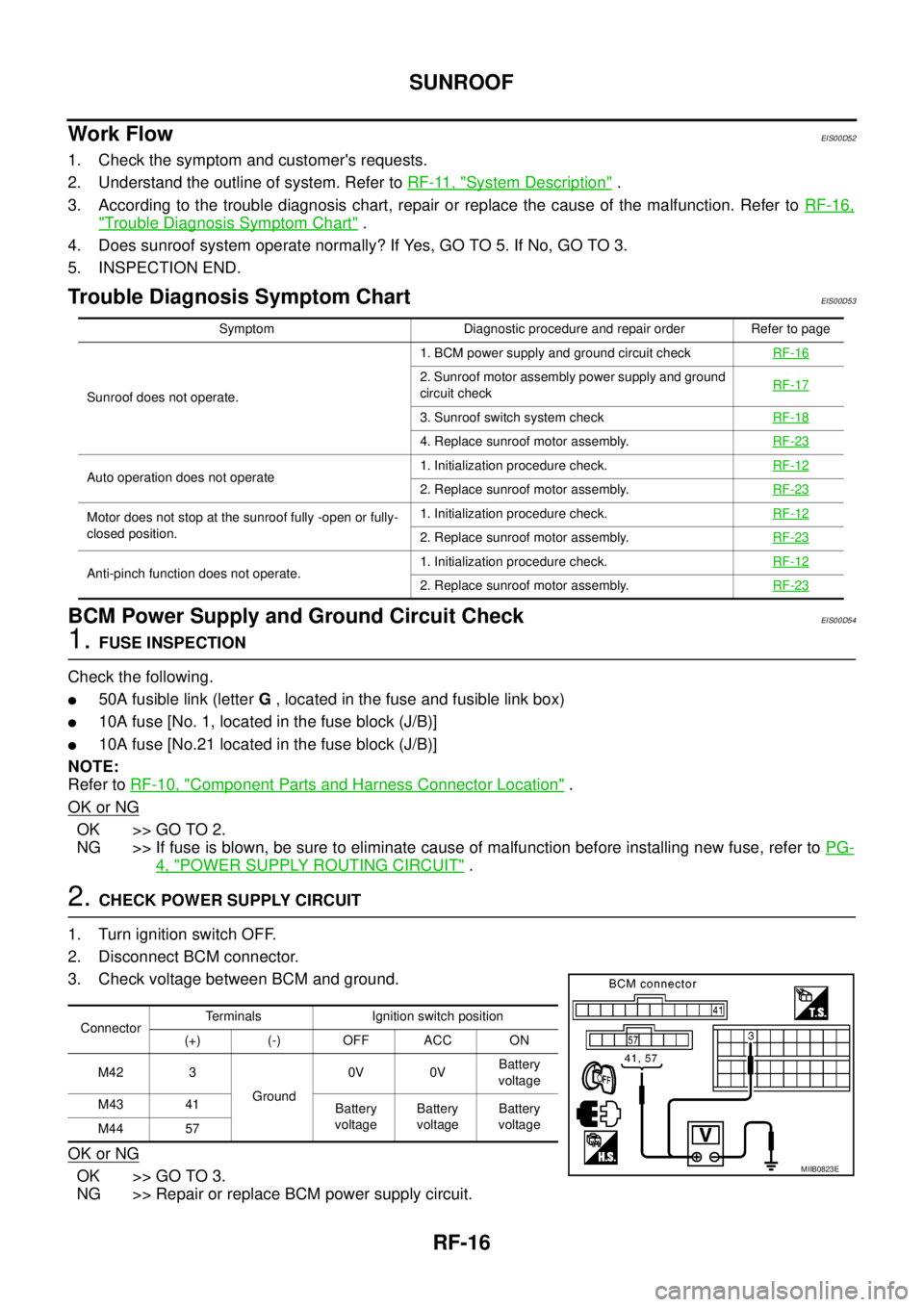
2.CHECK POWER SUPPLY CIRCUIT
1. Turn ignition switch OFF.
2. Disconnect BCM connector.
3. Check voltage between BCM and ground.
OK or NG
OK >> GO TO 3.
NG >> Repair or replace BCM power supply circuit.
Symptom Diagnostic procedure and repair order Refer to page
Sunroof does not operate.1. BCM power supply and ground circuit checkRF-16
2. Sunroof motor assembly power supply and ground
circuit checkRF-17
3. Sunroof switch system checkRF-18
4. Replace sunroof motor assembly.RF-23
Auto operation does not operate1. Initialization procedure check.RF-122. Replace sunroof motor assembly.RF-23
Motor does not stop at the sunroof fully -open or fully-
closed position.1. Initialization procedure check.RF-12
2. Replace sunroof motor assembly.RF-23
Anti-pinch function does not operate.1. Initialization procedure check.RF-122. Replace sunroof motor assembly.RF-23
ConnectorTerminals Ignition switch position
(+) (-) OFF ACC ON
M42 3
Ground0V 0VBattery
voltage
M43 41
Battery
voltageBattery
voltageBattery
voltage
M44 57
MIIB0823E
Page 2758 of 3171
![NISSAN NAVARA 2005 Repair Workshop Manual TROUBLE DIAGNOSIS FOR SYSTEM
RFD-55
[WITH ELECTRONIC LOCKING DIFFERENTIAL]
C
E
F
G
H
I
J
K
L
MA
B
RFD
DIAGNOSTIC PROCEDURE
1.CHECK POWER SUPPLY
1. Turn ignition switch “OFF”.
2. Disconnect differe NISSAN NAVARA 2005 Repair Workshop Manual TROUBLE DIAGNOSIS FOR SYSTEM
RFD-55
[WITH ELECTRONIC LOCKING DIFFERENTIAL]
C
E
F
G
H
I
J
K
L
MA
B
RFD
DIAGNOSTIC PROCEDURE
1.CHECK POWER SUPPLY
1. Turn ignition switch “OFF”.
2. Disconnect differe](/manual-img/5/57362/w960_57362-2757.png)
TROUBLE DIAGNOSIS FOR SYSTEM
RFD-55
[WITH ELECTRONIC LOCKING DIFFERENTIAL]
C
E
F
G
H
I
J
K
L
MA
B
RFD
DIAGNOSTIC PROCEDURE
1.CHECK POWER SUPPLY
1. Turn ignition switch “OFF”.
2. Disconnect differential lock control unit harness connector.
3. Check voltage between differential lock control unit harness
connector terminals and ground.
4. Turn ignition switch “ON”. (Do not start engine.)
5. Check voltage between differential lock control unit harness
connector terminals and ground.
OK or NG
OK >> GO TO 2.
NG >> Check the following. If any items are damaged, repair or
replace damaged parts.
l10A fuse [No. 3 or 19, located in fuse block (J/B)]
lHarness for short or open between battery and differential lock control unit harness connector
terminal 15
lHarness for short or open between ignition switch and differential lock control unit harness con-
nector terminals 1 and 2
lBattery and ignition switch. Refer toPG-4, "POWER SUPPLY ROUTING CIRCUIT".
2.CHECK GROUND CIRCUIT
1. Turn ignition switch “OFF”.
2. Disconnect differential lock control unit harness connector.
3. Check continuity between differential lock control unit harness
connector M107 terminals 3, 10 and ground.
Also check harness for short to ground and short to power.
OK or NG
OK >> GO TO 3.
NG >> Repair open circuit or short to ground or short to power
in harness or connectors.
Connector Terminal Voltage (Approx.)
M1071 - Ground 0V
2 - Ground 0V
15 - Ground Battery voltage
SDIA2562E
Connector Terminal Voltage (Approx.)
M1071 - Ground
Battery voltage 2 - Ground
15 - Ground
SDIA2563E
Continuity should exist.
SDIA2564E
Page 2761 of 3171
![NISSAN NAVARA 2005 Repair Workshop Manual RFD-58
[WITH ELECTRONIC LOCKING DIFFERENTIAL]
TROUBLE DIAGNOSIS FOR SYSTEM
2.CHECK DIFFERENTIAL LOCK MODE SWITCH SUPPLY CIRCUIT
1. Turn ignition switch “ON”.
2. Disconnect differential lock mode s NISSAN NAVARA 2005 Repair Workshop Manual RFD-58
[WITH ELECTRONIC LOCKING DIFFERENTIAL]
TROUBLE DIAGNOSIS FOR SYSTEM
2.CHECK DIFFERENTIAL LOCK MODE SWITCH SUPPLY CIRCUIT
1. Turn ignition switch “ON”.
2. Disconnect differential lock mode s](/manual-img/5/57362/w960_57362-2760.png)
RFD-58
[WITH ELECTRONIC LOCKING DIFFERENTIAL]
TROUBLE DIAGNOSIS FOR SYSTEM
2.CHECK DIFFERENTIAL LOCK MODE SWITCH SUPPLY CIRCUIT
1. Turn ignition switch “ON”.
2. Disconnect differential lock mode switch harness connector.
3. Check voltage between differential lock mode switch harness
connector terminal 3 and ground.
4. Turn ignition switch “OFF”.
5. Check voltage between differential lock mode switch harness
connector terminal 3 and ground.
OK or NG
OK >> GO TO 3.
NG >> Check the following. If any items are damaged, repair or
replace damaged parts.
l10A fuse [No. 3, located in fuse block (J/B)]
lHarness for short or open between ignition switch and differential lock mode switch harness
connector terminal 3
lIgnition switch. Refer toPG-4, "POWER SUPPLY ROUTING CIRCUIT".
3.CHECK DIFFERENTIAL LOCK MODE SWITCH
1. Turn ignition switch “OFF”.
2. Disconnect differential lock mode switch harness connector.
3. Operate differential lock mode switch and check continuity
between differential lock mode switch terminals.
OK or NG
OK >> GO TO 4.
NG >> Replace differential lock mode switch.
Connector Terminal Voltage (Approx.)
M108 3 - Ground Battery voltage
SDIA2534E
Connector Terminal Voltage (Approx.)
M108 3 - Ground 0V
SDIA2643E
Terminal Condition Continuity
1-3Differential lock mode switch: ON No
Differential lock mode switch: OFF Yes
2-3Differential lock mode switch: ON Yes
Differential lock mode switch: OFF No
SDIA2535E
Page 2773 of 3171
![NISSAN NAVARA 2005 Repair Workshop Manual RFD-70
[WITH ELECTRONIC LOCKING DIFFERENTIAL]
TROUBLE DIAGNOSIS FOR SYMPTOMS
TROUBLE DIAGNOSIS FOR SYMPTOMS
PFP:00007
DIFF LOCK Indicator Lamp Does Not Turn ONEDS003B9
SYMPTOM:
DIFF LOCK indicator lam NISSAN NAVARA 2005 Repair Workshop Manual RFD-70
[WITH ELECTRONIC LOCKING DIFFERENTIAL]
TROUBLE DIAGNOSIS FOR SYMPTOMS
TROUBLE DIAGNOSIS FOR SYMPTOMS
PFP:00007
DIFF LOCK Indicator Lamp Does Not Turn ONEDS003B9
SYMPTOM:
DIFF LOCK indicator lam](/manual-img/5/57362/w960_57362-2772.png)
RFD-70
[WITH ELECTRONIC LOCKING DIFFERENTIAL]
TROUBLE DIAGNOSIS FOR SYMPTOMS
TROUBLE DIAGNOSIS FOR SYMPTOMS
PFP:00007
DIFF LOCK Indicator Lamp Does Not Turn ONEDS003B9
SYMPTOM:
DIFF LOCK indicator lamp does not turn ON for approx. 1 second when turning ignition switch to
“ON”.
DIAGNOSTIC PROCEDURE
1.CHECK SYSTEM FOR CAN COMMUNICATION LINE
Perform self-diagnosis. Refer toRFD-51, "
SELF-DIAG RESULTS MODE".
Is
“CAN COMM CIRCUIT”displayed?
YES >> Perform trouble diagnosis for CAN communication line. Refer toRFD-69, "CAN Communication
Line".
NO >> GO TO 2.
2.CHECK DIFFERENTIAL LOCK CONTROL UNIT POWER SUPPLY
1. Turn ignition switch “OFF”.
2. Disconnect differential lock control unit harness connector.
3. Check voltage between differential lock control unit harness
connector terminals and ground.
4. Turn ignition switch “ON”. (Do not start engine.)
5. Check voltage between differential lock control unit harness
connector terminals and ground.
OK or NG
OK >> GO TO 3.
NG >> Check the following. If any items are damaged, repair or
replace damaged parts.
l10A fuse [No. 3 or 19, located in fuse block (J/B)]
lHarness for short or open between battery and differential lock control unit harness connector
terminal 15
lHarness for short or open between ignition switch and differential lock control unit harness con-
nector terminals 1 and 2
lBattery and ignition switch. Refer toPG-4, "POWER SUPPLY ROUTING CIRCUIT".
Connector Terminal Voltage (Approx.)
M1071 - Ground 0V
2 - Ground 0V
15 - Ground Battery voltage
SDIA2562E
Connector Terminal Voltage (Approx.)
M1071 - Ground
Battery voltage 2 - Ground
15 - Ground
SDIA2563E
Page 2774 of 3171
![NISSAN NAVARA 2005 Repair Workshop Manual TROUBLE DIAGNOSIS FOR SYMPTOMS
RFD-71
[WITH ELECTRONIC LOCKING DIFFERENTIAL]
C
E
F
G
H
I
J
K
L
MA
B
RFD
3.CHECK DIFFERENTIAL LOCK CONTROL UNIT GROUND CIRCUIT
1. Turn ignition switch “OFF”.
2. Disc NISSAN NAVARA 2005 Repair Workshop Manual TROUBLE DIAGNOSIS FOR SYMPTOMS
RFD-71
[WITH ELECTRONIC LOCKING DIFFERENTIAL]
C
E
F
G
H
I
J
K
L
MA
B
RFD
3.CHECK DIFFERENTIAL LOCK CONTROL UNIT GROUND CIRCUIT
1. Turn ignition switch “OFF”.
2. Disc](/manual-img/5/57362/w960_57362-2773.png)
TROUBLE DIAGNOSIS FOR SYMPTOMS
RFD-71
[WITH ELECTRONIC LOCKING DIFFERENTIAL]
C
E
F
G
H
I
J
K
L
MA
B
RFD
3.CHECK DIFFERENTIAL LOCK CONTROL UNIT GROUND CIRCUIT
1. Turn ignition switch “OFF”.
2. Disconnect differential lock control unit harness connector.
3. Check continuity between differential lock control unit harness
connector M107 terminals 3, 10 and ground.
Also check harness for short to ground and short to power.
OK or NG
OK >> GO TO 4.
NG >> Repair open circuit or short to ground or short to power
in harness or connectors.
4.CHECK COMBINATION METER POWER SUPPLY CIRCUIT
1. Turn ignition switch “OFF”.
2. Disconnect combination meter harness connector.
3. Check voltage between combination meter harness connector
terminal and ground.
4. Turn ignition switch “ON”. (Do not start engine.)
5. Check voltage between combination meter harness connector
terminal and ground.
OK or NG
OK >> GO TO 5.
NG >> Check the following. If any items are damaged, repair or
replace damaged parts.
l10A fuse [No.14, located in the fuse block (J/B)]
lHarness for short or open between ignition switch and combination meter harness connector
terminal 16.
lIgnition switch. Refer toPG-4, "POWER SUPPLY ROUTING CIRCUIT". Continuity should exist.
SDIA2564E
Connector Terminal Voltage (Approx.)
M23 16 - Ground 0V
WDIA0250E
Connector Terminal Voltage (Approx.)
M23 16 - Ground 0V
WDIA0251E
Page 2847 of 3171

SC-14
CHARGING SYSTEM
CHARGING SYSTEM
PFP:00011
System DescriptionEKS00MZA
The alternator provides DC voltage to operate the vehicle's electrical system and to keep the battery charged.
The voltage output is controlled by the IC regulator.
Power is supplied at all times to alternator terminal 4 through:
l15A fuse (No. 30, located in the fuse and fusible link box).
Terminal 1 supplies power to charge the battery and operate the vehicle's electrical system. Output voltage is
controlled by the IC regulator at terminal 4 detecting the input voltage. The charging circuit is protected by the
140A fusible link (letter "A", located in the fuse and fusible link box) .
The alternator is grounded to the engine block.
With the ignition switch in the ON or START position, power is supplied
l10A fuse [No. 14, located in the fuse block (J/B)]
lto combination meter terminal 16 for the charge warning lamp.
Ground is supplied With power and ground supplied
lto terminal 2 of the combination meter
lthrough terminal 3 of the alternator.
If the charge warning lamp illuminates with the engine running, a fault is indicated.
The charge warning lamp will illuminate. When the alternator is providing sufficient voltage with the engine
running, the ground is opened and the charge warning lamp will go off.
Page 2852 of 3171

CHARGING SYSTEM
SC-19
C
D
E
F
G
H
I
J
L
MA
B
SC
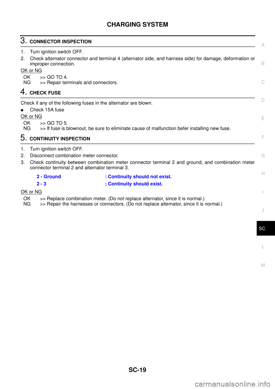
3.CONNECTOR INSPECTION
1. Turn ignition switch OFF.
2. Check alternator connector and terminal 4 (alternator side, and harness side) for damage, deformation or
improper connection.
OK or NG
OK >> GO TO 4.
NG >> Repair terminals and connectors.
4.CHECK FUSE
Check if any of the following fuses in the alternator are blown.
lCheck 15A fuse
OK or NG
OK >> GO TO 5.
NG >> If fuse is blownout, be sure to eliminate cause of malfunction befer installing new fuse.
5.CONTINUITY INSPECTION
1. Turn ignition switch OFF.
2. Disconnect combination meter connector.
3. Check continuity between combination meter connector terminal 2 and ground, and combination meter
connector terminal 2 and alternator terminal 3.
OK or NG
OK >> Replace combination meter. (Do not replace alternator, since it is normal.)
NG >> Repair the harnesses or connectors. (Do not replace alternator, since it is normal.)2 - Ground : Continuity should not exist.
2 - 3 : Continuity should exist.
Page 2854 of 3171

CHARGING SYSTEM
SC-21
C
D
E
F
G
H
I
J
L
MA
B
SC
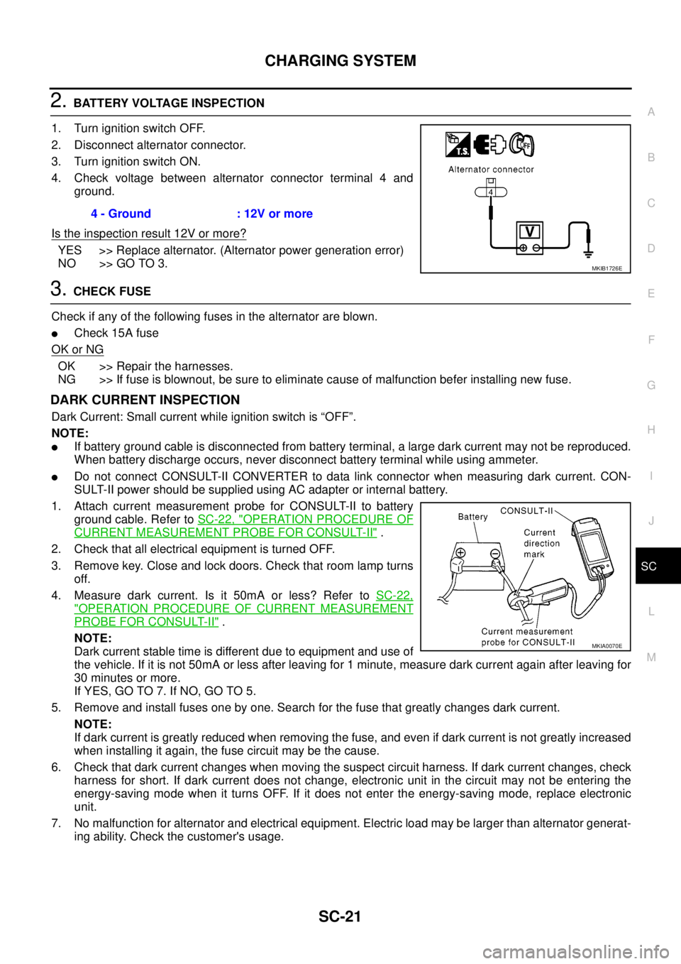
2.BATTERY VOLTAGE INSPECTION
1. Turn ignition switch OFF.
2. Disconnect alternator connector.
3. Turn ignition switch ON.
4. Check voltage between alternator connector terminal 4 and
ground.
Is the inspection result 12V or more?
YES >> Replace alternator. (Alternator power generation error)
NO >> GO TO 3.
3.CHECK FUSE
Check if any of the following fuses in the alternator are blown.
lCheck 15A fuse
OK or NG
OK >> Repair the harnesses.
NG >> If fuse is blownout, be sure to eliminate cause of malfunction befer installing new fuse.
DARK CURRENT INSPECTION
Dark Current: Small current while ignition switch is “OFF”.
NOTE:
lIf battery ground cable is disconnected from battery terminal, a large dark current may not be reproduced.
When battery discharge occurs, never disconnect battery terminal while using ammeter.
lDo not connect CONSULT-II CONVERTER to data link connector when measuring dark current. CON-
SULT-II power should be supplied using AC adapter or internal battery.
1. Attach current measurement probe for CONSULT-II to battery
ground cable. Refer toSC-22, "
OPERATION PROCEDURE OF
CURRENT MEASUREMENT PROBE FOR CONSULT-II".
2. Check that all electrical equipment is turned OFF.
3. Remove key. Close and lock doors. Check that room lamp turns
off.
4. Measure dark current. Is it 50mA or less? Refer toSC-22,
"OPERATION PROCEDURE OF CURRENT MEASUREMENT
PROBE FOR CONSULT-II".
NOTE:
Dark current stable time is different due to equipment and use of
the vehicle. If it is not 50mA or less after leaving for 1 minute, measure dark current again after leaving for
30 minutes or more.
If YES, GO TO 7. If NO, GO TO 5.
5. Remove and install fuses one by one. Search for the fuse that greatly changes dark current.
NOTE:
If dark current is greatly reduced when removing the fuse, and even if dark current is not greatly increased
when installing it again, the fuse circuit may be the cause.
6. Check that dark current changes when moving the suspect circuit harness. If dark current changes, check
harness for short. If dark current does not change, electronic unit in the circuit may not be entering the
energy-saving mode when it turns OFF. If it does not enter the energy-saving mode, replace electronic
unit.
7. No malfunction for alternator and electrical equipment. Electric load may be larger than alternator generat-
ing ability. Check the customer's usage.4 - Ground : 12V or more
MKIB1726E
MKIA0070E