Page 522 of 3171
AV-34
TERMINALS AND REFERENCE VALUE FOR CONTROL UNIT
TERMINALS AND REFERENCE VALUE FOR CONTROL UNIT
PFP:00000
Audio Unit (1CD Player Type)EKS00Q6B
Te r m i n a l
(Wire color)
ItemSignal
input/
outputCondition
Reference value
+-Ignition
switchOperation
2
(O)Ground Illumination signal Input ONLighting switch is ON. Approx. 12 V
Lighting switch is OFF. Approx. 0 V
3
(Y)Ground Battery power supply Input ON – Battery voltage
4
(Y)–TELmute – – – –
6
(V)Ground ACC power supply Input ACC – Battery voltage
7
(BR)5
(L)Audio signal front LH Output ON Sound output
8
(W)GroundVehicle speed signal
(2-pulse)Input ONWhen vehicle speed is
approx. 40 km/h (25
MPH).
9
(L)10
(V)Audio signal rear LH Output ON Sound output
12
(SB)– Immobilizer – – – –
13
(LG)11
(V)Audio signal front RH Output ON Sound output
15
(GR)16
(V)Audio signal rear RH Output ON Sound output
19
(W)–TELin(-) – – – –
SKIB1990E
ELF1080D
SKIB1990E
SKIB1990E
SKIB1990E
Page 523 of 3171

TERMINALS AND REFERENCE VALUE FOR CONTROL UNIT
AV-35
C
D
E
F
G
H
I
J
L
MA
B
AV
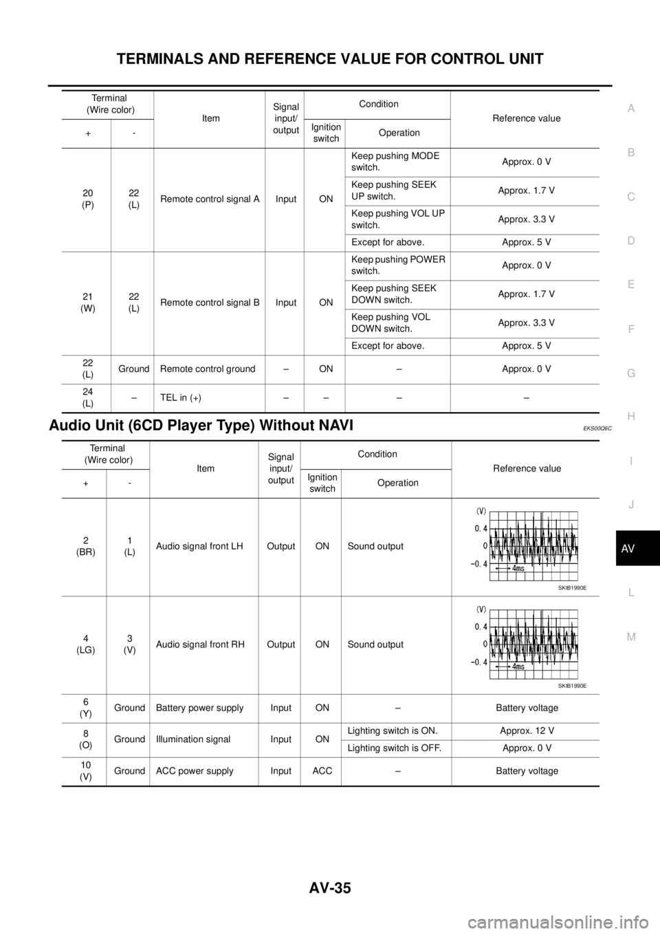
Audio Unit (6CD Player Type) Without NAVIEKS00Q6C
20
(P)22
(L)Remote control signal A Input ONKeep pushing MODE
switch.Approx. 0 V
Keep pushing SEEK
UP switch.Approx. 1.7 V
Keep pushing VOL UP
switch.Approx. 3.3 V
Except for above. Approx. 5 V
21
(W)22
(L)Remote control signal B Input ONKeep pushing POWER
switch.Approx. 0 V
Keep pushing SEEK
DOWN switch.Approx. 1.7 V
Keep pushing VOL
DOWN switch.Approx. 3.3 V
Except for above. Approx. 5 V
22
(L)Ground Remote control ground – ON – Approx. 0 V
24
(L)–TELin(+) – – – – Terminal
(Wire color)
ItemSignal
input/
outputCondition
Reference value
+-Ignition
switchOperation
Terminal
(Wire color)
ItemSignal
input/
outputCondition
Reference value
+-Ignition
switchOperation
2
(BR)1
(L)Audio signal front LH Output ON Sound output
4
(LG)3
(V)Audio signal front RH Output ON Sound output
6
(Y)Ground Battery power supply Input ON – Battery voltage
8
(O)Ground Illumination signal Input ONLighting switch is ON. Approx. 12 V
Lighting switch is OFF. Approx. 0 V
10
(V)Ground ACC power supply Input ACC – Battery voltage
SKIB1990E
SKIB1990E
Page 547 of 3171

DIAGNOSIS SYSTEM
AV-59
C
D
E
F
G
H
I
J
L
MA
B
AV
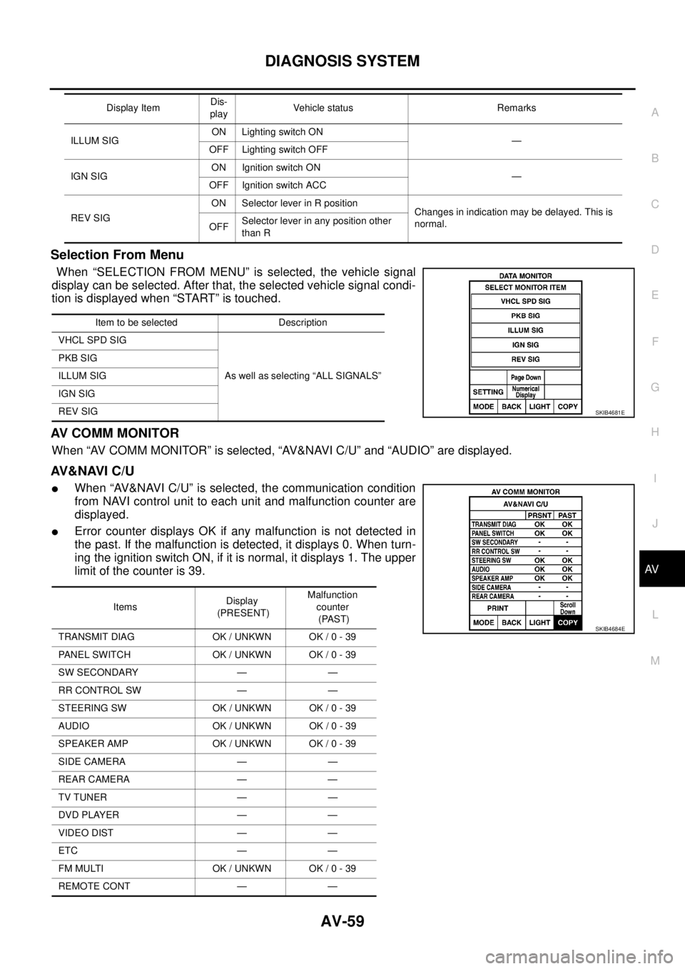
Selection From Menu
When “SELECTION FROM MENU” is selected, the vehicle signal
display can be selected. After that, the selected vehicle signal condi-
tion is displayed when “START” is touched.
AV C O M M M O N I T O R
When “AV COMM MONITOR” is selected, “AV&NAVI C/U” and “AUDIO” are displayed.
AV&NAVI C/U
lWhen “AV&NAVI C/U” is selected, the communication condition
from NAVI control unit to each unit and malfunction counter are
displayed.
lError counter displays OK if any malfunction is not detected in
the past. If the malfunction is detected, it displays 0. When turn-
ing the ignition switch ON, if it is normal, it displays 1. The upper
limitofthecounteris39.
ILLUM SIGON Lighting switch ON
—
OFF Lighting switch OFF
IGN SIGON Ignition switch ON
—
OFF Ignition switch ACC
REV SIGON Selector lever in R position
Changes in indication may be delayed. This is
normal.
OFFSelector lever in any position other
than R Display ItemDis-
playVehicle status Remarks
Item to be selected Description
VHCL SPD SIG
As well as selecting “ALL SIGNALS” PKB SIG
ILLUM SIG
IGN SIG
REV SIG
SKIB4681E
ItemsDisplay
(PRESENT)Malfunction
counter
(PAST)
TRANSMIT DIAG OK / UNKWN OK / 0 - 39
PANEL SWITCH OK / UNKWN OK / 0 - 39
SW SECONDARY — —
RR CONTROL SW — —
STEERING SW OK / UNKWN OK / 0 - 39
AUDIO OK / UNKWN OK / 0 - 39
SPEAKER AMP OK / UNKWN OK / 0 - 39
SIDE CAMERA — —
REAR CAMERA — —
TV TUNER — —
DVD PLAYER — —
VIDEO DIST — —
ETC — —
FM MULTI OK / UNKWN OK / 0 - 39
REMOTE CONT — —
SKIB4684E
Page 548 of 3171
AV-60
DIAGNOSIS SYSTEM
AUDIO
lWhen “AUDIO” is selected, the communication condition from
audio unit to each unit and malfunction counter are displayed.
lError counter displays OK if any malfunction is not detected in
the past. If the malfunction is detected, it displays 0. When turn-
ing the ignition switch ON, if it is normal, it displays 1. The upper
limitofthecounteris39.
ECU PART NUMBER
The part number of NAVI control unit is displayed.
ItemsDisplay
(PRESENT)Malfunction
counter
(PAST)
TRANSMIT DG OK / UNKWN OK / 0 - 39
SPEAKER AMP — —
TV TUNER — —
DVD PLAYER — —
MD DECK — —
CD CHANGER — —
MD CHANGER — —
SKIB4685E
SKIB3680E
Page 561 of 3171
REMOVAL AND INSTALLATION
AV-73
C
D
E
F
G
H
I
J
L
MA
B
AV
REMOVAL AND INSTALLATIONPFP:00000
Auido Unit (1CD Player Type)EKS00Q6U
REMOVAL
1. Remove cluster lid C. Refer toIP-10, "INSTRUMENT PANEL ASSEMBLY".
2. Remove screws (A) . Then remove audio unit (1) from vehicle.
INSTALLATION
Installation is the reverse order of removal.
Audio Unit ( 6CD Player Type ) Without NAVIEKS00Q6V
REMOVAL
1. Remove cluster lid C. Refer toIP-10, "INSTRUMENT PANEL ASSEMBLY".
2. Remove screws (A) . Then remove audio unit (1) from vehicle.
INSTALLATION
Installation is the reverse order of removal.
SKIB3890E
SKIB4405E
Page 562 of 3171
AV-74
REMOVAL AND INSTALLATION
Audio Unit (6CD Player Type) With NAVI
EKS00Q6W
REMOVAL
1. Remove cluster lid C. Refer toIP-10, "INSTRUMENT PANEL ASSEMBLY".
2. Remove screws (A). Then remove audio unit (1) from vehicle.
INSTALLATION
Installation is the reverse order of removal.
Front Door SpeakerEKS00Q6X
REMOVAL
1. Remove door finisher (front) . Refer toEI-30, "DOOR FINISHER".
2. Remove screws (A) and remove speaker (1).
INSTALLATION
Installation is the reverse order of removal.
Rear Door SpeakerEKS00Q6Y
REMOVAL
1. Remove door finisher (rear) . Refer toEI-30, "DOOR FINISHER".
2. Remove screws (A) and remove speaker (1).
INSTALLATION
Installation is the reverse order of removal.
SKIB4580E
SKIB3905E
SKIB3906E
Page 564 of 3171
AV-76
REMOVAL AND INSTALLATION
GPS Antenna
EKS00Q72
REMOVAL
l: Vehicle front
l(2) : GPS antenna
1. Remove display unit. Refer toAV-77, "
Display Unit".
2. Remove audio unit. Refer toAV-74, "
Audio Unit (6CD Player Type) With NAVI".
3. Disconnect connector (1) and remove clips (A).
4. Remove screws (A) and remove GPS antenna (1).
INSTALLATION
Installation is the reverse order of removal.
SKIB4583E
SKIB4584E
Page 825 of 3171
![NISSAN NAVARA 2005 Repair Workshop Manual PRECAUTIONS
BRC-3
[ABS]
C
D
E
G
H
I
J
K
L
MA
B
BRC
[ABS]PRECAUTIONSPFP:00001
Precautions for Supplemental Restraint System (SRS) “AIR BAG” and “SEAT
BELT PRE-TENSIONER”
EFS006DM
The Supplement NISSAN NAVARA 2005 Repair Workshop Manual PRECAUTIONS
BRC-3
[ABS]
C
D
E
G
H
I
J
K
L
MA
B
BRC
[ABS]PRECAUTIONSPFP:00001
Precautions for Supplemental Restraint System (SRS) “AIR BAG” and “SEAT
BELT PRE-TENSIONER”
EFS006DM
The Supplement](/manual-img/5/57362/w960_57362-824.png)
PRECAUTIONS
BRC-3
[ABS]
C
D
E
G
H
I
J
K
L
MA
B
BRC
[ABS]PRECAUTIONSPFP:00001
Precautions for Supplemental Restraint System (SRS) “AIR BAG” and “SEAT
BELT PRE-TENSIONER”
EFS006DM
The Supplemental Restraint System such as “AIR BAG” and “SEAT BELT PRE-TENSIONER”, used along
with a front seat belt, helps to reduce the risk or severity of injury to the driver and front passenger for certain
types of collision. Information necessary to service the system safely is included in the SRS and SB section of
this Service Manual.
WARNING:
lTo avoid rendering the SRS inoperative, which could increase the risk of personal injury or death
in the event of a collision which would result in air bag inflation, all maintenance must be per-
formed by an authorized NISSAN/INFINITI dealer.
lImproper maintenance, including incorrect removal and installation of the SRS, can lead to per-
sonal injury caused by unintentional activation of the system. For removal of Spiral Cable and Air
Bag Module, see the SRS section.
lDo not use electrical test equipment on any circuit related to the SRS unless instructed to in this
Service Manual. SRS wiring harnesses can be identified by yellow and/or orange harnesses or
harness connectors.
Precautions for Brake SystemEFS005TG
lRecommended fluid is brake fluid “DOT 3” or “DOT 4”.
lNever reuse drained brake fluid.
lBe careful not to splash brake fluid on painted areas.If brake fluid is splashed, wipe it off and flush area
with water immediately.
lNever use mineral oils such as gasoline or kerosene. They will ruin rubber parts of the hydraulic system.
lUse flare nut wrench when removing flare nuts, and use a flare
nut torque wrench when tighten flare nuts.
lBrake system is an important safety part.If a brake fluid leak is
detected, always disassemble the affected part.If a malfunction
is detected, replace part with new one.
lBefore working, turn ignition switch OFF and disconnect con-
nector of ABS actuator and electric unit (control unit) or the bat-
tery cables.
lWhen installing brake tube and hose, be sure to torque.
WARNING:
Clean brake pads and shoes with a waster cloth, then wipe with
a dust collector.
Precautions for Brake ControlEFS005TH
lJust after starting vehicle after ignition switch ON, brake pedal may vibrate or motor operating noise may
be heard from engine room. This is a normal status of operation check.
lStopping distance may be longer than that of vehicles without ABS when vehicle drives on rough, gravel,
or snow-covered (fresh, deep snow) roads.
lWhen an error is indicated by ABS or another warning lamp, collect all necessary information from cus-
tomer (what symptoms are present under what conditions) and check for simple causes before starting
diagnostic servicing. Besides electrical system inspection, check brake booster operation, brake fluid
level, and fluid leaks.
lIf tyre size and type are used in an improper combination, or brake pads are not Genuine NISSAN parts,
stopping distance or steering stability may deteriorate.
lIf there is a radio, antenna, or antenna lead-in wire (including wiring) near control module, ABS function
may have a malfunction or error.
lIf aftermarket parts (car stereo, CD player, etc.) have been installed, check for incidents such as harness
pinches, open circuits, and improper wiring.
SBR820BA