2005 NISSAN NAVARA cruise control
[x] Cancel search: cruise controlPage 214 of 3171

AT-206
TROUBLE DIAGNOSIS FOR SYMPTOMS
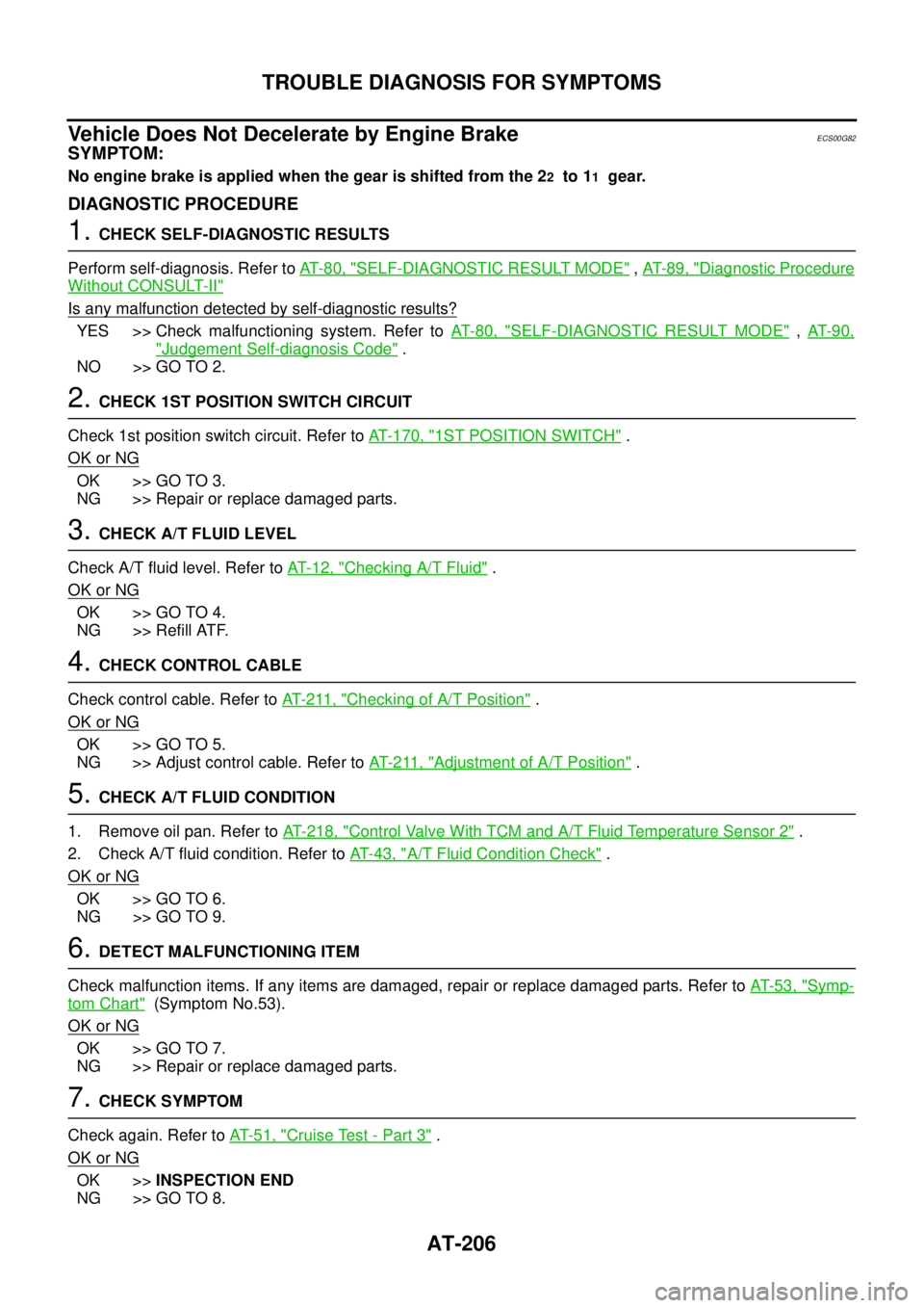
Vehicle Does Not Decelerate by Engine Brake
ECS00G82
SYMPTOM:
No engine brake is applied when the gear is shifted from the 22to 11gear.
DIAGNOSTIC PROCEDURE
1.CHECK SELF-DIAGNOSTIC RESULTS
Perform self-diagnosis. Refer toAT-80, "
SELF-DIAGNOSTIC RESULT MODE",AT-89, "Diagnostic Procedure
Without CONSULT-II"
Is any malfunction detected by self-diagnostic results?
YES >> Check malfunctioning system. Refer toAT-80, "SELF-DIAGNOSTIC RESULT MODE",AT- 9 0 ,
"Judgement Self-diagnosis Code".
NO >> GO TO 2.
2.CHECK 1ST POSITION SWITCH CIRCUIT
Check 1st position switch circuit. Refer toAT- 1 7 0 , "
1ST POSITION SWITCH".
OK or NG
OK >> GO TO 3.
NG >> Repair or replace damaged parts.
3.CHECK A/T FLUID LEVEL
Check A/T fluid level. Refer toAT-12, "
Checking A/T Fluid".
OK or NG
OK >> GO TO 4.
NG >> Refill ATF.
4.CHECK CONTROL CABLE
Check control cable. Refer toAT- 2 11 , "
Checking of A/T Position".
OK or NG
OK >> GO TO 5.
NG >> Adjust control cable. Refer toAT- 2 11 , "
Adjustment of A/T Position".
5.CHECK A/T FLUID CONDITION
1. Remove oil pan. Refer toAT- 2 1 8 , "
Control Valve With TCM and A/T Fluid Temperature Sensor 2".
2. Check A/T fluid condition. Refer toAT-43, "
A/T Fluid Condition Check".
OK or NG
OK >> GO TO 6.
NG >> GO TO 9.
6.DETECT MALFUNCTIONING ITEM
Check malfunction items. If any items are damaged, repair or replace damaged parts. Refer toAT-53, "
Symp-
tom Chart"(Symptom No.53).
OK or NG
OK >> GO TO 7.
NG >> Repair or replace damaged parts.
7.CHECK SYMPTOM
Check again. Refer toAT-51, "
Cruise Test - Part 3".
OK or NG
OK >>INSPECTION END
NG >> GO TO 8.
Page 1331 of 3171

ASCD INDICATOR
EC-351
C
D
E
F
G
H
I
J
K
L
MA
EC
ASCD INDICATORPFP:24814
Component DescriptionEBS01KMY
ASCD indicator lamp illuminates to indicate ASCD operation status. Lamp has two indicators, CRUISE and
SET, and is integrated in combination meter.
CRUISE indicator illuminates when MAIN switch on ASCD steering switch is turned ON to indicated that
ASCD system is ready for operation.
SET indicator illuminates when following conditions are met.
lCRUISE indicator is illuminated.
lSET/COAST switch on ASCD steering switch is turned ON while vehicle speed is within the range of
ASCD setting.
SET indicator remains lit during ASCD control.
Refer toEC-355, "
AUTOMATIC SPEED CONTROL DEVICE (ASCD)"for the ASCD function.
Page 1335 of 3171

AUTOMATIC SPEED CONTROL DEVICE (ASCD)
EC-355
C
D
E
F
G
H
I
J
K
L
MA
EC
AUTOMATIC SPEED CONTROL DEVICE (ASCD)PFP:18930
System DescriptionEBS01KN2
INPUT/OUTPUT SIGNAL CHART
*: This signal is sent to the ECM through CAN communication line.
BASIC ASCD SYSTEM
Refer to Owner's Manual for ASCD operating instructions.
Automatic Speed Control Device (ASCD) allows a driver to keep vehicle at predetermined constant speed
without depressing accelerator pedal. Driver can set vehicle speed in advance between approximately 40 km/
h(25MPH)and185km/h(115MPH).
ECM controls fuel injection value to regulate engine speed.
Operation status of ASCD is indicated by CRUISE indicator and SET indicator in combination meter. If any
malfunction occurs in ASCD system, it automatically deactivates control.
SET OPERATION
Press ASCD MAIN switch. (The CRUISE indicator in combination meter illuminates.)
When vehicle speed reaches a desired speed between approximately 40 km/h (25 MPH) and 185 km/h (115
MPH), press SET/COST switch. (Then SET indicator in combination meter illuminates.)
ACCEL OPERATION
If the RESUME/ACCELERATE switch is depressed during cruise control driving, increase the vehicle speed
until the switch is released or vehicle speed reaches maximum speed controlled by the system.
And then ASCD will keep the new set speed.
CANCEL OPERATION
When any of following conditions exist, cruise operation will be canceled.
lCANCEL switch is depressed
lMore than 2 switches at ASCD steering switch are depressed at the same time (Set speed will be cleared)
lBrake pedal is depressed
lClutch pedal is depressed or gear position is changed to the neutral position (M/T models)
lSelector lever is changed to N, P, R position (A/T models)
lVehicle speed decreased to 13 km/h (8 MPH) lower than the set speed
When the ECM detects any of the following conditions, the ECM will cancel the cruise operation and inform
the driver by blinking indicator lamp.
lMalfunction for some self-diagnoses regarding ASCD control: SET lamp will blink quickly.
If MAIN switch is turned to OFF during ASCD is activated, all of ASCD operations will be canceled and vehicle
speed memory will be erased.
COAST OPERATION
When the SET/COAST switch is depressed during cruise control driving, decrease vehicle set speed until the
switch is released. And then ASCD will keep the new set speed.
RESUME OPERATION
When the RESUME/ACCELERATE switch is depressed after cancel operation other than depressing MAIN
switch is performed, vehicle speed will return to last set speed. To resume vehicle set speed, vehicle condition
must meet following conditions.
Sensor Input signal to ECM ECM function Actuator
ASCD brake switch Brake pedal operation
ASCD vehicle speed control Fuel injector and Fuel pump Stop lamp switch Brake pedal operation
ASCD clutch switch (M/T) Clutch pedal operation
ASCD steering switch ASCD steering switch operation
Park/Neutral position (PNP)
switchGear position
Combination meter* Vehicle speed
TCM* Powertrain revolution
Page 1810 of 3171
![NISSAN NAVARA 2005 Repair Workshop Manual CAN COMMUNICATION
LAN-33
[CAN]
C
D
E
F
G
H
I
J
L
MA
B
LAN
Input/output signal chart
T: Transmit R: Receive
Signals ECMNAVI con-
trol unitFront air
controlBCMCombina-
tion meterABS actua-
tor and
elect NISSAN NAVARA 2005 Repair Workshop Manual CAN COMMUNICATION
LAN-33
[CAN]
C
D
E
F
G
H
I
J
L
MA
B
LAN
Input/output signal chart
T: Transmit R: Receive
Signals ECMNAVI con-
trol unitFront air
controlBCMCombina-
tion meterABS actua-
tor and
elect](/manual-img/5/57362/w960_57362-1809.png)
CAN COMMUNICATION
LAN-33
[CAN]
C
D
E
F
G
H
I
J
L
MA
B
LAN
Input/output signal chart
T: Transmit R: Receive
Signals ECMNAVI con-
trol unitFront air
controlBCMCombina-
tion meterABS actua-
tor and
electric unit
(control
unit)IPDM E/R
A/C compressor request signal TR
ASCD CRUISE lamp signal T R
ASCD SET lamp signal T R
Cooling fan speed request signal TR
Engine coolant temperature signal T R R
Engine speed signal T R R
Engine status signal T R R
Fuel consumption monitor signalTR
RT
Glow indicator signal T R
Glow relay signal T R
Malfunction indicator signal T R
A/C switch/indicator signal T
R
*
PTC heater signal R T
A/C switch signal R
R
*T
Buzzer output signal T R
Day time running light request signal R T R R
Door switch signal T R R
Front fog light request signal R T R R
Front wiper request signal T R
High beam request signal T R R
Horn chirp signal T R
Low beam request signal T R
Position light request signal T R R
Rear fog light request signal R T R
Rear window defogger switch signal
R
*TR
Sleep wake up signal T R R
Theft warning horn request signal T R
Trailer lamp signal T R
Turn indicator signal T R
Distance to empty signal R T
Fuel level low warning signal R T
ABS warning lamp signalRT
Vehicle speed signalR
*RT
RR
R
*RT
Front wiper stop position signal R T
Hood switch signal R T
Oil pressure switch signalRT
Rear window defogger control signal R T
Page 1811 of 3171
![NISSAN NAVARA 2005 Repair Workshop Manual LAN-34
[CAN]
CAN COMMUNICATION
NOTE:
*: Automatic air conditioner models only
TYPE 4/ TYPE 5
System diagram
lTy p e 4
lTy p e 5
Input/output signal chart
T: Transmit R: Receive
PKIC1394E
PKIC1395E
Sig NISSAN NAVARA 2005 Repair Workshop Manual LAN-34
[CAN]
CAN COMMUNICATION
NOTE:
*: Automatic air conditioner models only
TYPE 4/ TYPE 5
System diagram
lTy p e 4
lTy p e 5
Input/output signal chart
T: Transmit R: Receive
PKIC1394E
PKIC1395E
Sig](/manual-img/5/57362/w960_57362-1810.png)
LAN-34
[CAN]
CAN COMMUNICATION
NOTE:
*: Automatic air conditioner models only
TYPE 4/ TYPE 5
System diagram
lTy p e 4
lTy p e 5
Input/output signal chart
T: Transmit R: Receive
PKIC1394E
PKIC1395E
Signals ECM TCMNAVI
control
unitFront air
controlBCMCombi-
nation
meterABS
actuator
and elec-
tric unit
(control
unit)IPDM
E/R
A/C compressor request signal TR
Accelerator pedal position signal T R
ASCD CRUISE lamp signal T R
ASCD OD cancel request T R
ASCD operation signal T R
ASCD SET lamp signal T R
Battery voltage signal T R
Page 1816 of 3171
![NISSAN NAVARA 2005 Repair Workshop Manual CAN COMMUNICATION
LAN-39
[CAN]
C
D
E
F
G
H
I
J
L
MA
B
LAN
Input/output signal chart
T: Transmit R: Receive
Signals ECMNAVI
control
unitDiffer-
ential
lock
control
unitFront air
con-
trol
*1BCMCombi-
n NISSAN NAVARA 2005 Repair Workshop Manual CAN COMMUNICATION
LAN-39
[CAN]
C
D
E
F
G
H
I
J
L
MA
B
LAN
Input/output signal chart
T: Transmit R: Receive
Signals ECMNAVI
control
unitDiffer-
ential
lock
control
unitFront air
con-
trol
*1BCMCombi-
n](/manual-img/5/57362/w960_57362-1815.png)
CAN COMMUNICATION
LAN-39
[CAN]
C
D
E
F
G
H
I
J
L
MA
B
LAN
Input/output signal chart
T: Transmit R: Receive
Signals ECMNAVI
control
unitDiffer-
ential
lock
control
unitFront air
con-
trol
*1BCMCombi-
nation
meterTrans-
fer con-
trol unitABS
actua-
tor and
electric
unit
(control
unit)IPDM
E/R
A/C compressor request signal TR
ASCD CRUISE lamp signal T R
ASCD SET lamp signal T R
Cooling fan speed request signal TR
Engine coolant temperature signal T R R
Engine speed signal T R R R
Engine status signal T R R
Fuel consumption monitor signalTR
RT
Glow indicator signal T R
Glow relay signal T R
Malfunction indicator signal T R
A/C switch/indicator signal T
R
*2
Differential lock indicator signal T R
Differential lock switch signal T R
PTC heater signal
*3RT
A/C switch signal R
R
*2T
Buzzer output signal T R
Day time running light request signal R T R R
Door switch signal T R R
Front fog light request signal R T R R
Front wiper request signal T R
High beam request signal T R R
Horn chirp signal T R
Low beam request signal T R
Position light request signal T R R
Rear fog light request signal R T R
Rear window defogger switch signal R T R
Sleep wake up signal T R R
Theft warning horn request signal T R
Trailer lamp signal T R
Turn indicator signal T R
Distance to empty signal R T
Fuel level low warning signal R T
4WD shift switch signal R T
ABS warning lamp signal R T
Stop lamp switch signalRT
Page 1818 of 3171
![NISSAN NAVARA 2005 Repair Workshop Manual CAN COMMUNICATION
LAN-41
[CAN]
C
D
E
F
G
H
I
J
L
MA
B
LAN
lType 14
lType 15
Input/output signal chart
T: Transmit R: Receive
PKIC1402E
PKIC1384E
Signals ECM TCMNAVI
con-
trol
unitDiffer-
ential
lock
c NISSAN NAVARA 2005 Repair Workshop Manual CAN COMMUNICATION
LAN-41
[CAN]
C
D
E
F
G
H
I
J
L
MA
B
LAN
lType 14
lType 15
Input/output signal chart
T: Transmit R: Receive
PKIC1402E
PKIC1384E
Signals ECM TCMNAVI
con-
trol
unitDiffer-
ential
lock
c](/manual-img/5/57362/w960_57362-1817.png)
CAN COMMUNICATION
LAN-41
[CAN]
C
D
E
F
G
H
I
J
L
MA
B
LAN
lType 14
lType 15
Input/output signal chart
T: Transmit R: Receive
PKIC1402E
PKIC1384E
Signals ECM TCMNAVI
con-
trol
unitDiffer-
ential
lock
con-
trol
unitFront
air
controlBCMCom-
bina-
tion
meterTrans-
fer
con-
trol
unitABS
actua-
tor and
elec-
tric unit
(con-
trol
unit)IPDM
E/R
A/C compressor request signal TR
Accelerator pedal position signal T R
ASCD CRUISE lamp signal T R
ASCD OD cancel request T R
ASCD operation signal T R
ASCD SET lamp signal T R
Battery voltage signal T R
Closed throttle position signal T R
Cooling fan speed request signal TR
Page 2281 of 3171

MA-6
DESCRIPTION
ROAD TEST
Check clutch operation
Check foot brake operation
Check parking brake operation
Check steering operation, self-centering and steering wheel alignment
Check engine performance
Check for squeaks, rattles and noise from interior, suspension and brakes
Check heating, ventilation and air conditioning operation
Check radio, cassette and CD player operation
Check odometer and trip meter operation and cancelling
Check instruments for operation
Check automatic transmission/transaxle shift pattern and kickdown operation (if applicable)
Check cruise control and navigation system operation (if applicable)
ENGINE OPERATING AND HOT
Check idle speed
Check automatic transmission/transaxle oil level (if applicable)
FINAL INSPECTION
Remove vehicle protection kit
Fit interior mats and wheel covers
Check for interior and exterior metal and paint damage
Wash, clean interior and exterior
: Not applicable to this model