2005 NISSAN NAVARA ECU
[x] Cancel search: ECUPage 1694 of 3171

GW-8
SQUEAK AND RATTLE TROUBLE DIAGNOSES
TRUNK
Trunk noises are often caused by a loose jack or loose items put into the trunk by the owner.
In addition look for:
1. Trunk lid dumpers out of adjustment
2. Trunk lid striker out of adjustment
3. Trunk lid torsion bars knocking together
4. A loose license plate or bracket
Most of these incidents can be repaired by adjusting, securing or insulating the item(s) or component(s) caus-
ing the noise.
SUNROOF/HEADLINING
Noises in the sunroof/headlining area can often be traced to one of the following:
1. Sunroof lid, rail, linkage or seals making a rattle or light knocking noise
2. Sunvisor shaft shaking in the holder
3. Front or rear windshield touching headlining and squeaking
Again, pressing on the components to stop the noise while duplicating the conditions can isolate most of these
incidents. Repairs usually consist of insulating with felt cloth tape.
SEATS
When isolating seat noise it's important to note the position the seat is in and the load placed on the seat when
the noise is present. These conditions should be duplicated when verifying and isolating the cause of the
noise.
Cause of seat noise include:
1. Headrest rods and holder
2. A squeak between the seat pad cushion and frame
3. Rear seatback lock and bracket
These noises can be isolated by moving or pressing on the suspected components while duplicating the con-
ditions under which the noise occurs. Most of these incidents can be repaired by repositioning the component
or applying urethane tape to the contact area.
UNDERHOOD
Some interior noise may be caused by components under the hood or on the engine wall. The noise is then
transmitted into the passenger compartment.
Causes of transmitted underhood noise include:
1. Any component mounted to the engine wall
2. Components that pass through the engine wall
3. Engine wall mounts and connectors
4. Loose radiator mounting pins
5. Hood bumpers out of adjustment
6. Hood striker out of adjustment
These noises can be difficult to isolate since they cannot be reached from the interior of the vehicle. The best
method is to secure, move or insulate one component at a time and test drive the vehicle. Also, engine RPM
or load can be changed to isolate the noise. Repairs can usually be made by moving, adjusting, securing, or
insulating the component causing the noise.
Page 1698 of 3171

GW-12
WINDSHIELD GLASS
lWhile the urethane adhesive is curing, open a door window. This will prevent the glass from being forced
out by passenger compartment air pressure when a door is closed.
lThe molding must be installed securely so that it is in position and leaves no gap.
lInform the customer that the vehicle should remain stationary until the urethane adhesive has completely
cured (preferably 24 hours). Curing time varies with temperature and humidity.
lInstall parts removed.
WARNING:
lKeep heat and open flames away as primers and adhesive are flammable.
lThe materials contained in the kit are harmful if swallowed, and may irritate skin and eyes. Avoid
contact with the skin and eyes.
lUse in an open, well ventilated location. Avoid breathing the vapors. They can be harmful if
inhaled. If affected by vapor inhalation, immediately move to an area with fresh air.
lDriving the vehicle before the urethane adhesive has completely cured may affect the perfor-
mance of the windshield in case of an accident.
CAUTION:
lDo not use an adhesive which is past its usable term. Shelf life of this product is limited to six
months after the date of manufacture. Carefully adhere to the expiration or manufacture date
printed on the box.
lKeep primers and adhesive in a cool, dry place. Ideally, they should be stored in a refrigerator.
lDo not leave primers or adhesive cartridge unattended with their caps open or off.
lThe vehicle should not be driven for at least 24 hours or until the urethane adhesive has com-
pletely cured. Curing time varies depending on temperature and humidities. The curing time will
increase under lower temperatures and lower humidities.
Page 1723 of 3171
FRONT DOOR GLASS AND REGULATOR
GW-37
C
D
E
F
G
H
J
K
L
MA
B
GW
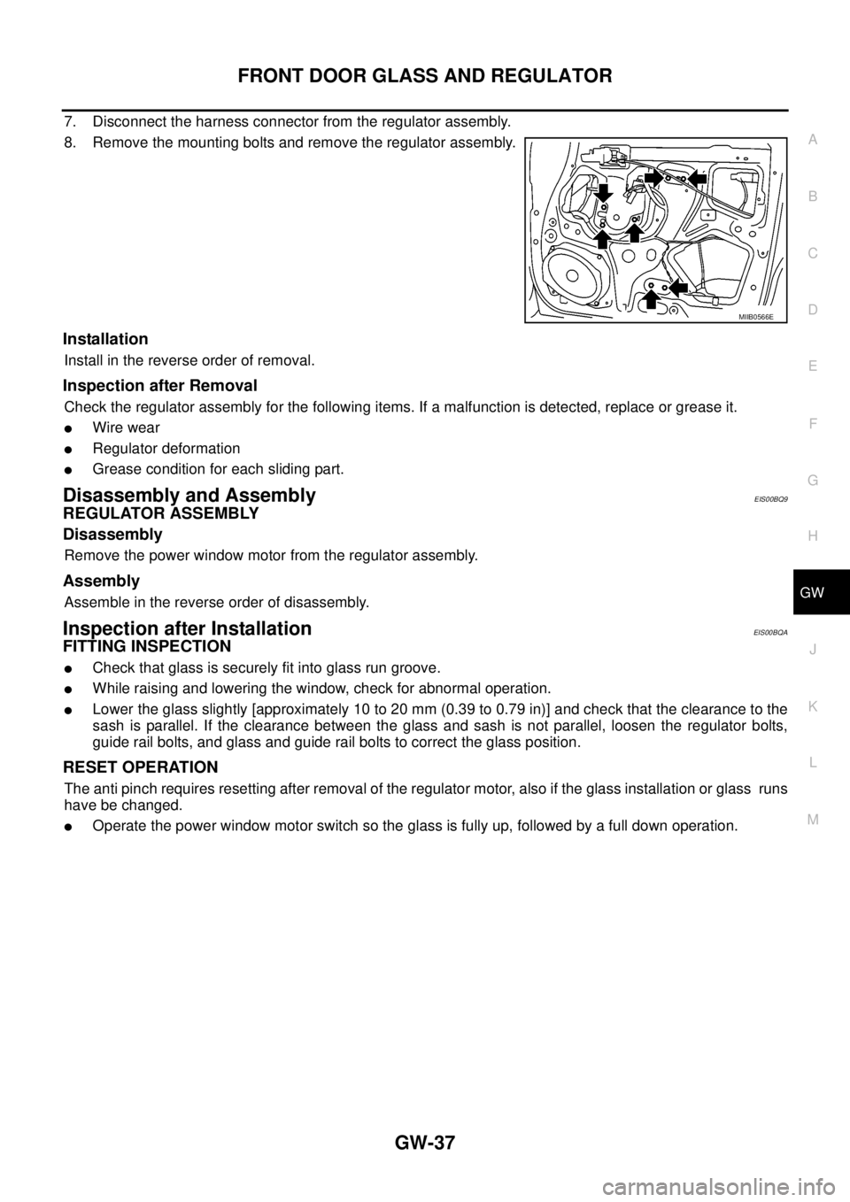
7. Disconnect the harness connector from the regulator assembly.
8. Remove the mounting bolts and remove the regulator assembly.
Installation
Install in the reverse order of removal.
Inspection after Removal
Check the regulator assembly for the following items. If a malfunction is detected, replace or grease it.
lWire wear
lRegulator deformation
lGrease condition for each sliding part.
Disassembly and AssemblyEIS00BQ9
REGULATOR ASSEMBLY
Disassembly
Remove the power window motor from the regulator assembly.
Assembly
Assemble in the reverse order of disassembly.
Inspection after InstallationEIS00BQA
FITTING INSPECTION
lCheck that glass is securely fit into glass run groove.
lWhile raising and lowering the window, check for abnormal operation.
lLower the glass slightly [approximately 10 to 20 mm (0.39 to 0.79 in)] and check that the clearance to the
sash is parallel. If the clearance between the glass and sash is not parallel, loosen the regulator bolts,
guide rail bolts, and glass and guide rail bolts to correct the glass position.
RESET OPERATION
The anti pinch requires resetting after removal of the regulator motor, also if the glass installation or glass runs
have be changed.
lOperate the power window motor switch so the glass is fully up, followed by a full down operation.
MIIB0566E
Page 1726 of 3171
GW-40
REAR DOOR GLASS AND REGULATOR
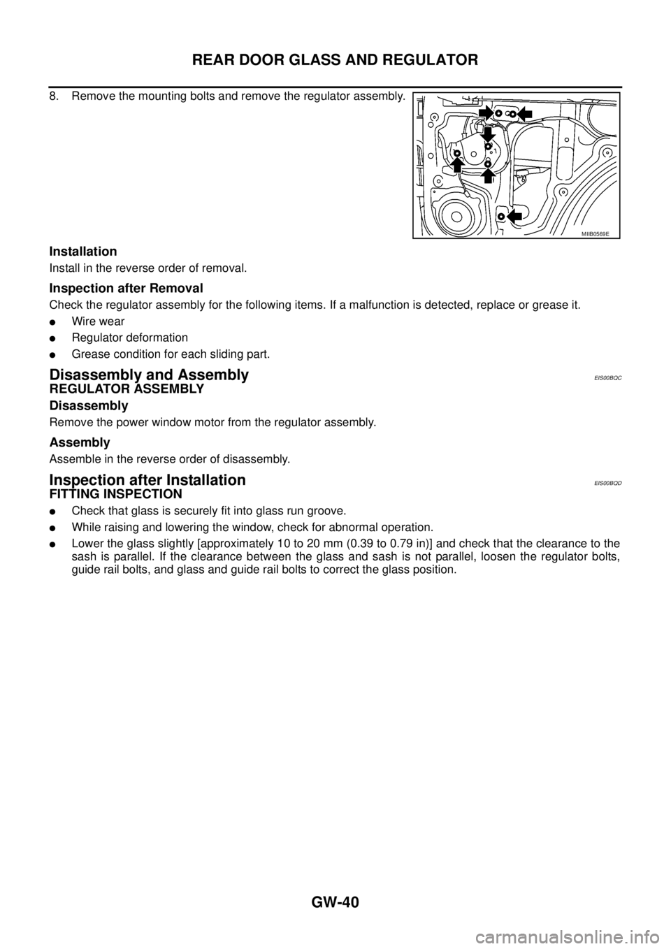
8. Remove the mounting bolts and remove the regulator assembly.
Installation
Install in the reverse order of removal.
Inspection after Removal
Check the regulator assembly for the following items. If a malfunction is detected, replace or grease it.
lWire wear
lRegulator deformation
lGrease condition for each sliding part.
Disassembly and AssemblyEIS00BQC
REGULATOR ASSEMBLY
Disassembly
Remove the power window motor from the regulator assembly.
Assembly
Assemble in the reverse order of disassembly.
Inspection after InstallationEIS00BQD
FITTING INSPECTION
lCheck that glass is securely fit into glass run groove.
lWhile raising and lowering the window, check for abnormal operation.
lLower the glass slightly [approximately 10 to 20 mm (0.39 to 0.79 in)] and check that the clearance to the
sash is parallel. If the clearance between the glass and sash is not parallel, loosen the regulator bolts,
guide rail bolts, and glass and guide rail bolts to correct the glass position.
MIIB0569E
Page 1740 of 3171
GW-54
REAR WINDOW DEFOGGER
CONSULT-II Function (BCM)
EIS00B8M
CONSULT-II can display each diagnostic item using the diagnostic test modes shown following.
CONSULT-II BASIC OPERATION PROCEDURE
CAUTION:
If CONSULT-II is used with no connection of CONSULT-II CONVERTER, malfunctions might be
detected in self-diagnosis depending on control unit which carry out CAN communication.
1. Turn ignition switch OFF.
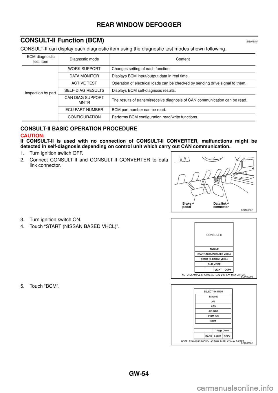
2. Connect CONSULT-II and CONSULT-II CONVERTER to data
link connector.
3. Turn ignition switch ON.
4. Touch “START (NISSAN BASED VHCL)”.
5. Touch “BCM”.
BCM diagnostic
test itemDiagnostic mode Content
Inspection by partWORK SUPPORT Changes setting of each function.
DATA MONITOR Displays BCM input/output data in real time.
ACTIVE TEST Operation of electrical loads can be checked by sending drive signal to them.
SELF-DIAG RESULTS Displays BCM self-diagnosis results.
CAN DIAG SUPPORT
MNTRThe results of transmit/receive diagnosis of CAN communication can be read.
ECU PART NUMBER BCM part number can be read.
CONFIGURATION Performs BCM configuration read/write functions.
BBIA0538E
BCIA0029E
BCIA0030E
Page 1746 of 3171
GW-60
REAR WINDOW DEFOGGER
2.CHECK REAR WINDOW DEFOGGER GROUND CIRCUIT
1. Turn ignition switch OFF.
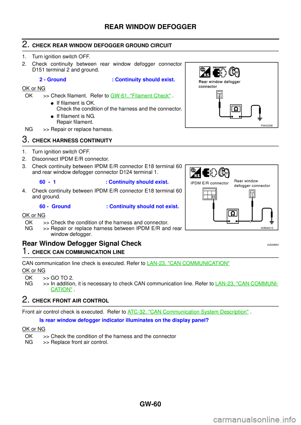
2. Check continuity between rear window defogger connector
D151 terminal 2 and ground.
OK or NG
OK >> Check filament. Refer toGW-61, "Filament Check".
lIf filament is OK.
Check the condition of the harness and the connector.
lIf filament is NG.
Repair filament.
NG >> Repair or replace harness.
3.CHECK HARNESS CONTINUITY
1. Turn ignition switch OFF.
2. Disconnect IPDM E/R connector.
3. Check continuity between IPDM E/R connector E18 terminal 60
and rear window defogger connector D124 terminal 1.
4. Check continuity between IPDM E/R connector E18 terminal 60
and ground.
OK or NG
OK >> Check the condition of the harness and connector.
NG >> Repair or replace harness between IPDM E/R and rear
window defogger.
Rear Window Defogger Signal CheckEIS00B8V
1.CHECK CAN COMMUNICATION LINE
CAN communication line check is executed. Refer toLAN-23, "
CAN COMMUNICATION"
OK or NG
OK >> GO TO 2.
NG >> In addition, it is necessary to check CAN communication line. Refer toLAN-23, "
CAN COMMUNI-
CATION".
2.CHECK FRONT AIR CONTROL
Front air control check is executed. Refer toAT C - 3 2 , "
CAN Communication System Description".
OK or NG
OK >> Check the condition of the harness and the connector
NG >> Replace front air control.2 - Ground : Continuity should exist.
PIIA4235E
60 - 1 : Continuity should exist.
60 - Ground : Continuity should not exist.
MIIB0621E
Is rear window defogger indicator illuminates on the display panel?
Page 1752 of 3171
GW-66
DOOR MIRROR
5. Lightly lift up lower side of mirror surface from mirror surface, and detach two pawls of upper side as if
pulling it out. Remove mirror surface from mirror body.
NOTE:
Be certain not to allow grease on sealing agent in center of mirror body assembly (actuator) or back side of
mirror surface (mirror holder).
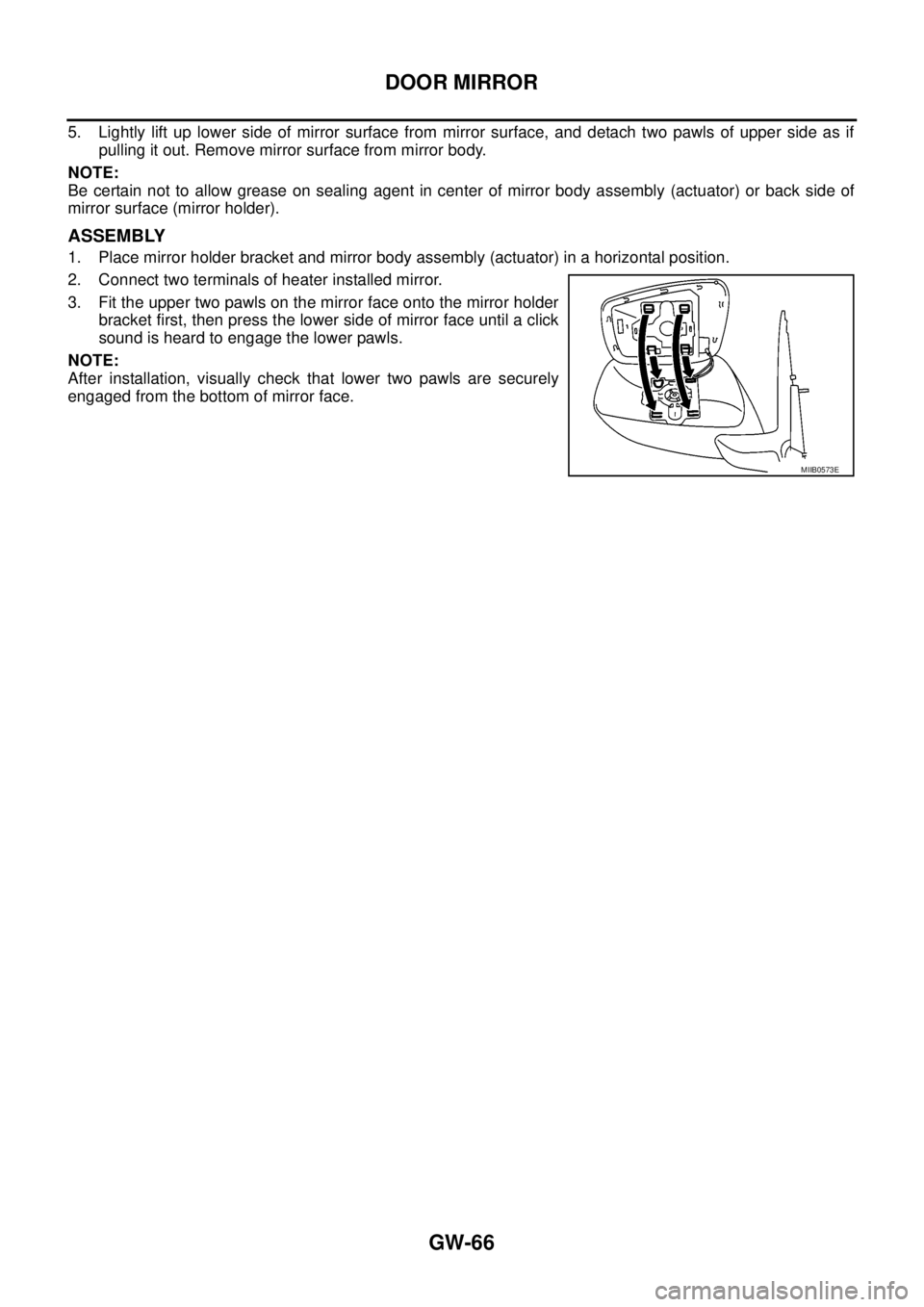
ASSEMBLY
1. Place mirror holder bracket and mirror body assembly (actuator) in a horizontal position.
2. Connect two terminals of heater installed mirror.
3. Fit the upper two pawls on the mirror face onto the mirror holder
bracket first, then press the lower side of mirror face until a click
sound is heard to engage the lower pawls.
NOTE:
After installation, visually check that lower two pawls are securely
engaged from the bottom of mirror face.
MIIB0573E
Page 1764 of 3171
SQUEAK AND RATTLE TROUBLE DIAGNOSES
IP-5
C
D
E
F
G
H
J
K
L
MA
B
IP
DUPLICATE THE NOISE AND TEST DRIVE
If possible, drive the vehicle with the customer until the noise is duplicated. Note any additional information on
the Diagnostic Worksheet regarding the conditions or location of the noise. This information can be used to
duplicate the same conditions when you confirm the repair.
If the noise can be duplicated easily during the test drive, to help identify the source of the noise, try to dupli-
cate the noise with the vehicle stopped by doing one or all of the following:
1) Close a door.
2) Tap or push/pull around the area where the noise appears to be coming from.
3) Rev the engine.
4) Use a floor jack to recreate vehicle “twist”.
5) At idle, apply engine load (electrical load, half-clutch on M/T model, drive position on A/T model).
6) Raisethevehicleonahoistandhitatirewitharubberhammer.
lDrive the vehicle and attempt to duplicate the conditions the customer states exist when the noise occurs.
lIf it is difficult to duplicate the noise, drive the vehicle slowly on an undulating or rough road to stress the
vehicle body.
CHECK RELATED SERVICE BULLETINS
After verifying the customer concern or symptom, check ASIST for Technical Service Bulletins (TSBs) related
to that concern or symptom.
If a TSB relates to the symptom, follow the procedure to repair the noise.
LOCATE THE NOISE AND IDENTIFY THE ROOT CAUSE
1. Narrow down the noise to a general area.To help pinpoint the source of the noise, use a listening tool
(Engine Ear and mechanic's stethoscope).
2. Narrow down the noise to a more specific area and identify the cause of the noise by:
lremoving the components in the area that you suspect the noise is coming from.
Do not use too much force when removing clips and fasteners, otherwise clips and fasteners can be bro-
ken or lost during the repair, resulting in the creation of new noise.
ltapping or pushing/pulling the component that you suspect is causing the noise.
Do not tap or push/pull the component with excessive force, otherwise the noise will be eliminated only
temporarily.
lfeeling for a vibration with your hand by touching the component(s) that you suspect is (are) causing the
noise.
lplacing a piece of paper between components that you suspect are causing the noise.
llooking for loose components and contact marks.
Refer toIP-6, "
Generic Squeak and Rattle Troubleshooting".
REPAIR THE CAUSE
lIf the cause is a loose component, tighten the component securely.
lIf the cause is insufficient clearance between components:
–separate components by repositioning or loosening and retightening the component, if possible.
–insulate components with a suitable insulator such as urethane pads, foam blocks, felt cloth tape or ure-
thane tape. A NISSAN Squeak and Rattle Kit (J-43980) is available through your authorized NISSAN
Parts Department.
CAUTION:
Do not use excessive force as many components are constructed of plastic and may be damaged.
Always check with the Parts Department for the latest parts information.
CONFIRM THE REPAIR
Confirm that the cause of a noise is repaired by test driving the vehicle. Operate the vehicle under the same
conditions as when the noise originally occurred. Refer to the notes on the Diagnostic Worksheet.