Page 2520 of 3171
REFRIGERANT LINES
MTC-133
C
D
E
F
G
H
I
K
L
MA
B
MTC
CHECKING PROCEDURE
To prevent inaccurate or false readings, make sure there is no refrigerant vapor, shop chemicals, or cigarette
smoke in the vicinity of the vehicle. Perform the leak test in calm area (low air/wind movement) so that the
leaking refrigerant is not dispersed.
1. Turn engine OFF.
2. Connect a suitable A/C manifold gauge set (SST) to the A/C service valves.
3. Check if the A/C refrigerant pressure is at least 345 kPa (3.45 bar, 3.52 kg/cm
2, 50 psi) above 16°C. If
less than specification, recover/evacuate and recharge the system with the specified amount of refriger-
ant.
NOTE:
At temperatures below 16°C, leaks may not be detected since the system may not reach 345 kPa (3.45
bar, 3.52 kg/cm
2,50psi).
4. Perform the leak test from the high-pressure side (compressor discharge a to evaporator inlet g) to the
low-pressure side (evaporator drain hose h to shaft seal l). Refer toMTC-120, "
Components". Perform a
leak check for the following areas carefully. Clean the component to be checked and move the leak
detected probe completely around the connection/component.
Compressor
Check the fitting of high- and low-pressure flexible hoses, relief valve and shaft seal.
Liquid tank
Check the refrigerant pressure sensor.
Service valves
Check all around the service valves. Ensure service valve caps are secured on the service valves (to pre-
vent leaks).
NOTE:
After removing A/C manifold gauge set from service valves, wipe any residue from valves to prevent any
false readings by leak detector.
Cooling unit (Evaporator)
With engine OFF, turn blower fan on “High” for at least 15 seconds to dissipate any refrigerant trace in the
cooling unit. Wait a minimum of 10 minutes accumulation time (refer to the manufacturer’s recommended
procedure for actual wait time) before inserting the leak detector probe into the drain hose.
Keep the probe inserted for at least 10 seconds. Use caution not to contaminate the probe tip with water
or dirt that may be in the drain hose.
5. If a leak detector detects a leak, verify at least once by blowing compressed air into area of suspected
leak, then repeat check as outlined above.
6. Do not stop when one leak is found. Continue to check for additional leaks at all system components.
If no leaks are found, perform steps 7 - 10.
7. Start engine.
8. Set the heater A/C control as follows;
a. A/C switch: ON
b. MODE control dial: VENT (Ventilation)
c. Intake door position: Recirculation
d. Max. cold temperature
e. Fan speed: High
9. Run engine at 1,500 rpm for at least 2 minutes.
10. Turn engine off and perform leak check again following steps 4 through 6 above.
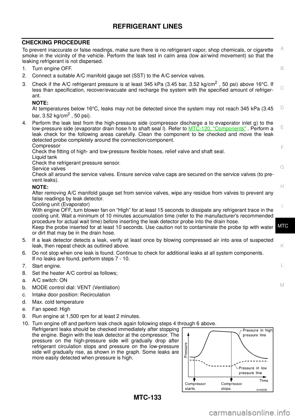
Refrigerant leaks should be checked immediately after stopping
the engine. Begin with the leak detector at the compressor. The
pressure on the high-pressure side will gradually drop after
refrigerant circulation stops and pressure on the low-pressure
side will gradually rise, as shown in the graph. Some leaks are
more easily detected when pressure is high.
SHA839E
Page 2525 of 3171
PB-2
PARKING BRAKE CONTROL
PARKING BRAKE CONTROL
PFP:36010
On-Vehicle ServiceEFS006AJ
INSPECTION
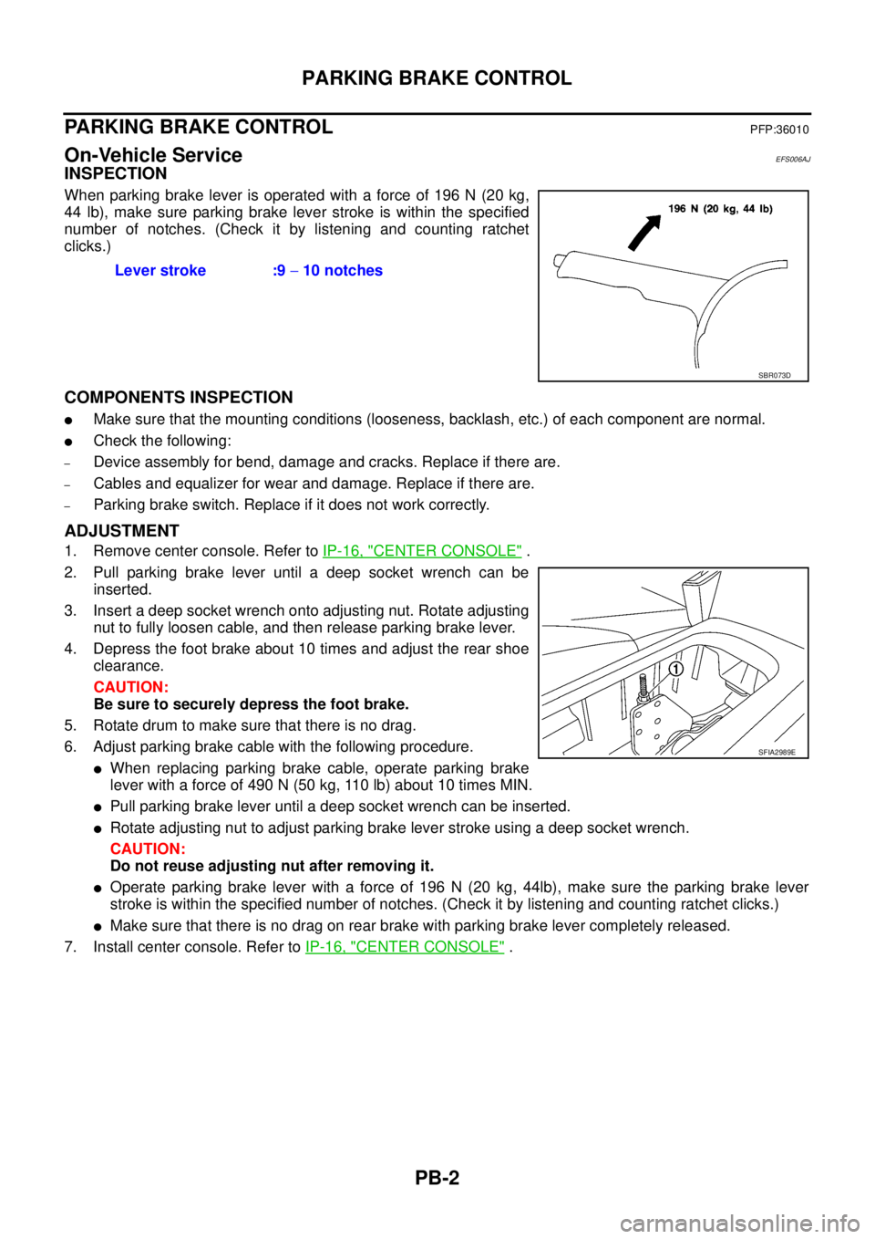
When parking brake lever is operated with a force of 196 N (20 kg,
44 lb), make sure parking brake lever stroke is within the specified
number of notches. (Check it by listening and counting ratchet
clicks.)
COMPONENTS INSPECTION
lMake sure that the mounting conditions (looseness, backlash, etc.) of each component are normal.
lCheck the following:
–Device assembly for bend, damage and cracks. Replace if there are.
–Cables and equalizer for wear and damage. Replace if there are.
–Parking brake switch. Replace if it does not work correctly.
ADJUSTMENT
1. Remove center console. Refer toIP-16, "CENTER CONSOLE".
2. Pull parking brake lever until a deep socket wrench can be
inserted.
3. Insert a deep socket wrench onto adjusting nut. Rotate adjusting
nut to fully loosen cable, and then release parking brake lever.
4. Depress the foot brake about 10 times and adjust the rear shoe
clearance.
CAUTION:
Be sure to securely depress the foot brake.
5. Rotate drum to make sure that there is no drag.
6. Adjust parking brake cable with the following procedure.
lWhen replacing parking brake cable, operate parking brake
leverwithaforceof490N(50kg,110lb)about10timesMIN.
lPull parking brake lever until a deep socket wrench can be inserted.
lRotate adjusting nut to adjust parking brake lever stroke using a deep socket wrench.
CAUTION:
Do not reuse adjusting nut after removing it.
lOperate parking brake lever with a force of 196 N (20 kg, 44lb), make sure the parking brake lever
stroke is within the specified number of notches. (Check it by listening and counting ratchet clicks.)
lMake sure that there is no drag on rear brake with parking brake lever completely released.
7. Install center console. Refer toIP-16, "
CENTER CONSOLE". Lever stroke :9-10 notches
SBR073D
SFIA2989E
Page 2641 of 3171
PS-14
POWER STEERING GEAR AND LINKAGE
POWER STEERING GEAR AND LINKAGE
PFP:49001
Removal and InstallationEGS001LJ
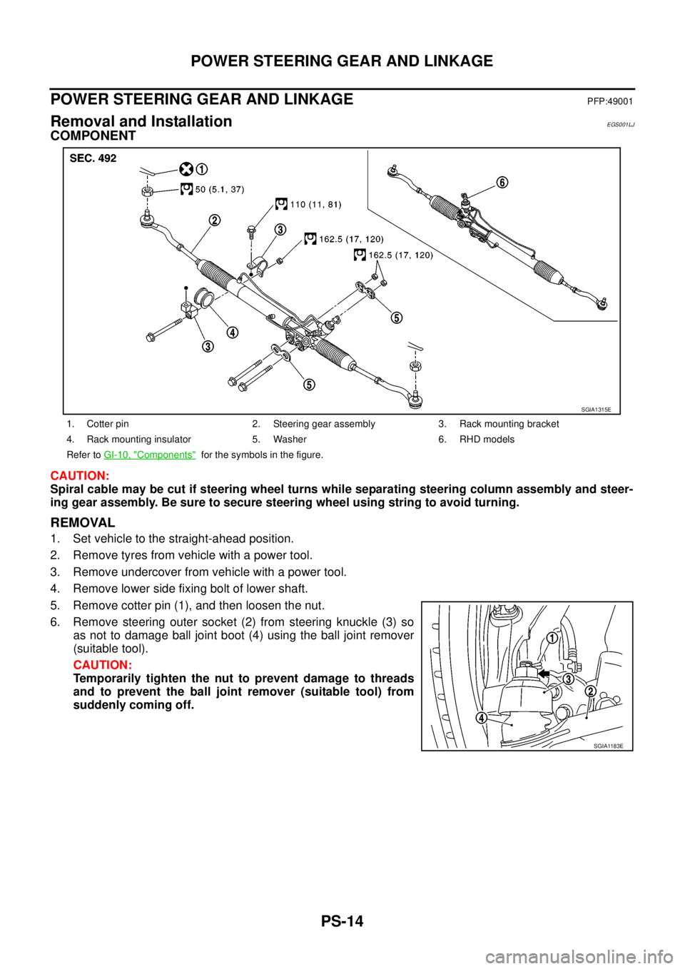
COMPONENT
CAUTION:
Spiral cable may be cut if steering wheel turns while separating steering column assembly and steer-
ing gear assembly. Be sure to secure steering wheel using string to avoid turning.
REMOVAL
1. Set vehicle to the straight-ahead position.
2. Remove tyres from vehicle with a power tool.
3. Remove undercover from vehicle with a power tool.
4. Remove lower side fixing bolt of lower shaft.
5. Remove cotter pin (1), and then loosen the nut.
6. Remove steering outer socket (2) from steering knuckle (3) so
as not to damage ball joint boot (4) using the ball joint remover
(suitable tool).
CAUTION:
Temporarily tighten the nut to prevent damage to threads
and to prevent the ball joint remover (suitable tool) from
suddenly coming off.
1. Cotter pin 2. Steering gear assembly 3. Rack mounting bracket
4. Rack mounting insulator 5. Washer 6. RHD models
Refer toGI-10, "
Components"for the symbols in the figure.
SGIA1315E
SGIA1183E
Page 2643 of 3171
PS-16
POWER STEERING GEAR AND LINKAGE
Disassembly and Assembly
EGS001LK
COMPONENT
CAUTION:
lDisassemble and assemble steering gear assembly by securing the mounting area in a vise using
copper plates.
lClean steering gear assembly with kerosene before disassembling. Be careful to avoid splashing
or applying any kerosene over connector of discharge port or return port.
1. Outer socket 2. Boot clamp 3. Boot
4. Inner socket 5. Boot clamp 6. Gear housing assembly
7. Cylinder tubes 8. Rear cover cap 9. Rear cover
10. O-ring A 11. Pinion assembly 12. Rack oil seal
13. Rack assembly 14. Rack Teflon ring 15. O-ring B
16. End cover assembly
Refer toGI-10, "
Components"and the followings for the symbols in the figure.
:
Apply Type DEXRON
TMIII or equivalent.
:A p p l y G e n u i n e T h r e a d L o c k i n g S e a l a n t , T h r e e B o u n d T B 1111 o r e q u i v a l e n t .
:Apply multi-purpose grease.
SGIA1349E
Page 2654 of 3171
POWER STEERING OIL PUMP
PS-27
C
D
E
F
H
I
J
K
L
MA
B
PS
DISASSEMBLY
NOTE:
Secure oil pump in a vise if necessary.
CAUTION:
Use copper plates when securing in a vise.
1. Remove rear bracket mounting bolts, and then remove rear bracket from rear cover.
2. Remove rear cover mounting bolts, and then remove rear cover from body assembly.
3. Remove gasket from body assembly.
4. Remove dowel pin, cartridge and side plate from body assembly.
5. Remove pulley mounting nut and washer, then remove pulley from drive shaft.
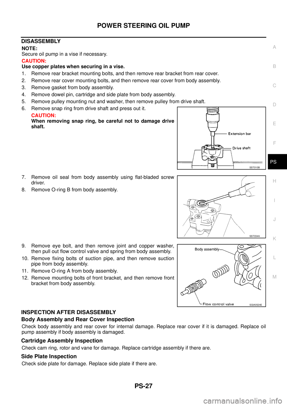
6. Remove snap ring from drive shaft and press out it.
CAUTION:
When removing snap ring, be careful not to damage drive
shaft.
7. Remove oil seal from body assembly using flat-bladed screw
driver.
8. Remove O-ring B from body assembly.
9. Remove eye bolt, and then remove joint and copper washer,
then pull out flow control valve and spring from body assembly.
10. Remove fixing bolts of suction pipe, and then remove suction
pipe from body assembly.
11. Remove O-ring A from body assembly.
12. Remove mounting bolts of front bracket, and then remove front
bracket from body assembly.
INSPECTION AFTER DISASSEMBLY
Body Assembly and Rear Cover Inspection
Check body assembly and rear cover for internal damage. Replace rear cover if it is damaged. Replace oil
pump assembly if body assembly is damaged.
Cartridge Assembly Inspection
Check cam ring, rotor and vane for damage. Replace cartridge assembly if there are.
Side Plate Inspection
Check side plate for damage. Replace side plate if there are.
SST010B
SST034A
SGIA0524E
Page 2655 of 3171
PS-28
POWER STEERING OIL PUMP
Flow Control Valve Inspection
Check flow control valve and spring for damage. Replace if there are.
ASSEMBLY
NOTE:
Secureoilpumpinaviseifnecessary.
CAUTION:
Use copper plates when securing in a vise.
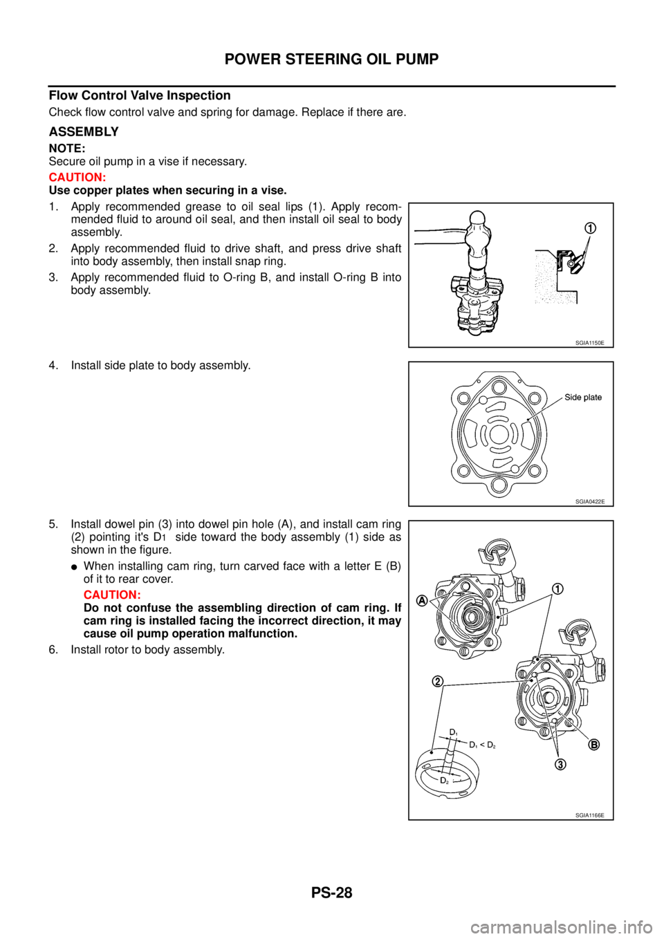
1. Apply recommended grease to oil seal lips (1). Apply recom-
mended fluid to around oil seal, and then install oil seal to body
assembly.
2. Apply recommended fluid to drive shaft, and press drive shaft
into body assembly, then install snap ring.
3. Apply recommended fluid to O-ring B, and install O-ring B into
body assembly.
4. Install side plate to body assembly.
5. Install dowel pin (3) into dowel pin hole (A), and install cam ring
(2) pointing it's D
1side toward the body assembly (1) side as
showninthefigure.
lWhen installing cam ring, turn carved face with a letter E (B)
of it to rear cover.
CAUTION:
Do not confuse the assembling direction of cam ring. If
cam ring is installed facing the incorrect direction, it may
cause oil pump operation malfunction.
6. Install rotor to body assembly.
SGIA1150E
SGIA0422E
SGIA1166E
Page 2657 of 3171
PS-30
HYDRAULIC LINE
HYDRAULIC LINE
PFP:49721
Component (RHD Models)EGS001LO
CAUTION:
Securely insert harness connector to pressure sensor.
1. Reservoir tank 2. Reservoir tank bracket 3. Suction hose
4. High pressure hose 5. Oil pump assembly 6. Steering gear assembly
SGIA1319E
Page 2659 of 3171
PS-32
HYDRAULIC LINE
Component (LHD Models)
EGS001LP
CAUTION:
Securely insert harness connector to pressure sensor.
1. Reservoir tank 2. Reservoir tank bracket 3. Suction hose
4. High pressure hose 5. Oil pump assembly 6. Steering gear assembly
7. Eye-bolt 8. Pressure sensor 9. Copper washer
SGIA1320E