Page 3014 of 3171

TROUBLE DIAGNOSIS
TF-47
C
E
F
G
H
I
J
K
L
MA
B
TF
DATA MONITOR MODE
Operation Procedure
1. Perform “CONSULT-II SETTING PROCEDURE”. Refer toTF-44, "CONSULT-II SETTING PROCEDURE"
.
2. Touch “DATA MONITOR”.
3. Select from “SELECT MONITOR ITEM”, screen of data monitor mode is displayed.
NOTE:
When malfunction is detected, CONSULT-II performs REAL-TIME DIAGNOSIS.
Also, any malfunction detected while in this mode will be displayed in real time.
Display Item List
´: Standard –: Not applicable
Monitored item (Unit)Monitor item selection
Remarks
ECU INPUT
SIGNALSMAIN
SIGNALSSELECTION
FROM MENU
VHCL/S SEN·FR [km/h] or [mph]´–´For ABS models, wheel speed calculated
by ABS actuator and electric unit (control
unit). Signal input with CAN communica-
tion line.
VHCL/S SEN·RR [km/h] or [mph]´–´For ABS models, wheel speed calculated
by TCM. Signal input with CAN communi-
cation line.
ENGINE SPEED [rpm]´–´Engine speed is displayed.
Signal input with CAN communication line.
BATTERY VOLT [V]´–´Power supply voltage for transfer control
unit.
2WD SWITCH [ON/OFF]´–´
4WD shift switch signal status is dis-
played.
(4L means 4LO of 4WD shift switch.) 4H SWITCH [ON/OFF]´–´
4L SWITCH [ON/OFF]´–´
4L POSI SW [ON/OFF]´–´This means 4LO switch.
4LO switch signal status is displayed.
ATP SWITCH [ON/OFF]´–´ATP switch signal status is displayed.
WAIT DETCT SW [ON/OFF]´–´Wait detection switch signal status is dis-
played.
4WD MODE [2H/4H/4L] –´´Control status of 4WD recognized by
transfer control unit. (2WD, 4H or 4LO)
VHCL/S COMP [km/h] or [mph] –´´Vehicle speed recognized by transfer con-
trol unit.
SHIFT ACT 1 [ON/OFF] –´´Output condition to actuator motor (clock-
wise)
SHIFT AC MON 1 [ON/OFF] – –´Check signal for transfer control unit sig-
nal output
SHIFT ACT 2 [ON/OFF] –´´Output condition to actuator motor (coun-
terclockwise)
SHIFT AC MON 2 [ON/OFF] – –´Check signal for transfer control unit sig-
nal output
SFT ACT/R MON [ON/OFF] – –´Operating condition of actuator motor
relay (integrated in transfer control unit)
SHIFT POS SW 1 [ON/OFF]´–´Condition of actuator position switch 1
SHIFT POS SW 2 [ON/OFF]´–´Condition of actuator position switch 2
SHIFT POS SW 3 [ON/OFF]´–´Condition of actuator position switch 3
SHIFT POS SW 4 [ON/OFF]´–´Condition of actuator position switch 4
Page 3015 of 3171
TF-48
TROUBLE DIAGNOSIS
4WD FAIL LAMP [ON/OFF] –´´Control status of 4WD warning lamp is dis-
played.
2WD IND [ON/OFF] – –´Control status of 4WD shift indicator lamp
(rear) is displayed.
4H IND [ON/OFF] – –´Control status of 4WD shift indicator lamp
(front and center) is displayed.
4L IND [ON/OFF] – –´Control status of 4LO indicator lamp is dis-
played.
Vo l ta g e [V ] – –´The value measured by the voltage probe
is displayed.
Frequency [Hz] – –´
The value measured by the pulse probe is
displayed. DUTY-HI (high) [%] – –´
DUTY-LOW (low) [%] – –´
PLS WIDTH-HI [msec] – –´
PLS WIDTH-LOW [msec] – –´ Monitored item (Unit)Monitor item selection
Remarks
ECU INPUT
SIGNALSMAIN
SIGNALSSELECTION
FROM MENU
Page 3103 of 3171

TF-136
SHIFT CONTROL
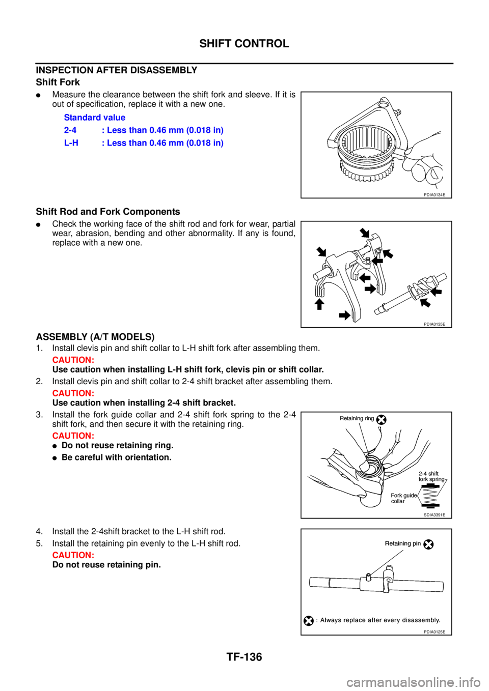
INSPECTION AFTER DISASSEMBLY
Shift Fork
lMeasure the clearance between the shift fork and sleeve. If it is
out of specification, replace it with a new one.
Shift Rod and Fork Components
lCheck the working face of the shift rod and fork for wear, partial
wear, abrasion, bending and other abnormality. If any is found,
replace with a new one.
ASSEMBLY (A/T MODELS)
1. Install clevis pin and shift collar to L-H shift fork after assembling them.
CAUTION:
Use caution when installing L-H shift fork, clevis pin or shift collar.
2. Install clevis pin and shift collar to 2-4 shift bracket after assembling them.
CAUTION:
Use caution when installing 2-4 shift bracket.
3. Install the fork guide collar and 2-4 shift fork spring to the 2-4
shift fork, and then secure it with the retaining ring.
CAUTION:
lDo not reuse retaining ring.
lBe careful with orientation.
4. Install the 2-4shift bracket to the L-H shift rod.
5. Install the retaining pin evenly to the L-H shift rod.
CAUTION:
Do not reuse retaining pin.Standard value
2-4 : Less than 0.46 mm (0.018 in)
L-H : Less than 0.46 mm (0.018 in)
PDIA0134E
PDIA0135E
SDIA3391E
PDIA0125E
Page 3104 of 3171
SHIFT CONTROL
TF-137
C
E
F
G
H
I
J
K
L
MA
B
TF
6. Install the drum cam to the control shift rod, and then secure it
with the retaining pin.
CAUTION:
Do not reuse retaining pin.
7. Install the snap ring to the control shift rod.
CAUTION:
Do not reuse snap ring.
ASSEMBLY (M/T MODELS)
1. Install clevis pin and shift collar to L-H shift fork after assembling them.
CAUTION:
Use caution when installing L-H shift fork, clevis pin or shift collar.
2. Install clevis pin and shift collar to 2-4 shift bracket after assembling them.
CAUTION:
Use caution when installing 2-4 shift bracket.
3. Install the fork guide collar and 2-4 shift fork spring to the 2-4
shift fork, and then secure it with the retaining ring.
CAUTION:
lDo not reuse retaining ring.
lBe careful with orientation.
PDIA0122E
SDIA3391E