2005 NISSAN NAVARA ECU
[x] Cancel search: ECUPage 2660 of 3171
HYDRAULIC LINE
PS-33
C
D
E
F
H
I
J
K
L
MA
B
PS
Removal and InstallationEGS001LQ
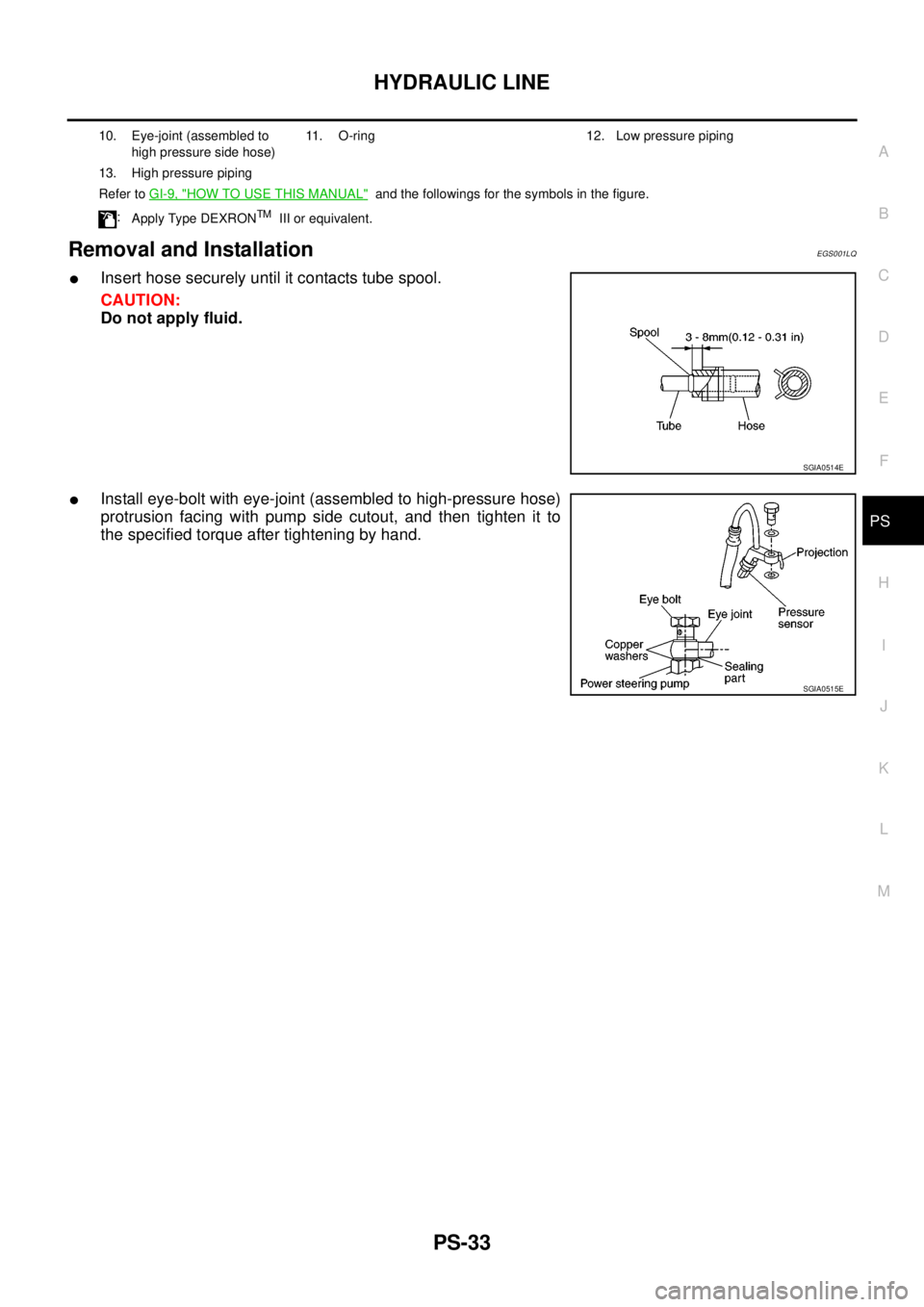
lInsert hose securely until it contacts tube spool.
CAUTION:
Do not apply fluid.
lInstall eye-bolt with eye-joint (assembled to high-pressure hose)
protrusion facing with pump side cutout, and then tighten it to
the specified torque after tightening by hand.
10. Eye-joint (assembled to
high pressure side hose)11. O-ring 12. Low pressure piping
13. High pressure piping
Refer toGI-9, "
HOW TO USE THIS MANUAL"and the followings for the symbols in the figure.
:
Apply Type DEXRON
TMIII or equivalent.
SGIA0514E
SGIA0515E
Page 2671 of 3171
![NISSAN NAVARA 2005 Repair Workshop Manual RAX-8
[M226]
AXLE SHAFT
REMOVAL
1. Remove the wheel.
2. Remove the rear brake drum. Refer toBR-31, "
Removal and Installation of Drum Brake Assembly".
3. Remove four lock nuts and spring washers secur NISSAN NAVARA 2005 Repair Workshop Manual RAX-8
[M226]
AXLE SHAFT
REMOVAL
1. Remove the wheel.
2. Remove the rear brake drum. Refer toBR-31, "
Removal and Installation of Drum Brake Assembly".
3. Remove four lock nuts and spring washers secur](/manual-img/5/57362/w960_57362-2670.png)
RAX-8
[M226]
AXLE SHAFT
REMOVAL
1. Remove the wheel.
2. Remove the rear brake drum. Refer toBR-31, "
Removal and Installation of Drum Brake Assembly".
3. Remove four lock nuts and spring washers securing the axle
shaft retainer to the rear axle case.
4. Using a wire, suspend the baffle plate to the sub frame.
NOTE:
Brake hose and brake cable do not need to be disconnected from the baffle plate and wheel cylinder.
CAUTION:
lBe careful not to deform brake tube.
lDo not bend the parking brake cable.
lWhile removing drum, never depress brake pedal because the piston will pop out.
5. Remove the axle shaft assembly from the rear axle case as
shown.
6. Using a puller remove the bearing cup from the rear axle case.
CAUTION:
lThe axle shaft bearing cup may stay in place in the axle
shaft housing. Remove the cup carefully so as not to
damage the inner surface of the axle shaft housing.
7. Usingapuller,removetheaxleshaftguideandoilsealfromthe
rear axle case.
NOTE:
Rear final drive oil will spill while removing the oil seal. Use a drain pan under the rear axle case to drain
oil.
10. Baffle plate 11. Bearing cup 12. Axle shaft guide
13. Oil seal 14. Breather 15. Rear axle case
LDIA0112E
WDIA0182E
Tool number : ST33290001
Tool number : ST33290001
MDIB9050E
Page 2672 of 3171
![NISSAN NAVARA 2005 Repair Workshop Manual AXLE SHAFT
RAX-9
[M226]
C
E
F
G
H
I
J
K
L
MA
B
RAX
INSPECTION AFTER REMOVAL
Axle Shaft Bearing and Cup
lCheck that the axle shaft bearing and cup roll freely and are free from noise, cracks, pitting a NISSAN NAVARA 2005 Repair Workshop Manual AXLE SHAFT
RAX-9
[M226]
C
E
F
G
H
I
J
K
L
MA
B
RAX
INSPECTION AFTER REMOVAL
Axle Shaft Bearing and Cup
lCheck that the axle shaft bearing and cup roll freely and are free from noise, cracks, pitting a](/manual-img/5/57362/w960_57362-2671.png)
AXLE SHAFT
RAX-9
[M226]
C
E
F
G
H
I
J
K
L
MA
B
RAX
INSPECTION AFTER REMOVAL
Axle Shaft Bearing and Cup
lCheck that the axle shaft bearing and cup roll freely and are free from noise, cracks, pitting and wear.
Replace if necessary.
Axle Shaft Retainer
lCheck for deformation and cracks. Replace if necessary.
Rear Axle Case
lCheck the exterior and inner machined surfaces for deformation and cracks. Replace if necessary.
INSTALLATION
Installation is in the reverse order of removal.
When installing pay attention to following points:
lInstall a new shaft guide and a new oil seal into the rear axle case.
CAUTION:
lDo not reuse the axle oil seal. The axle oil seal must be replaced every time the axle shaft assem-
bly is removed from the axle shaft housing.
lWhen installing oil seals, apply multi-purpsose grease to oil seal lips.
lInstall four new lock nuts to secure the axle shaft assembly to the rear axle case, and tighten lock nuts to
the specified torque. Refer toRAX-7, "
Removal and Installation".
lReinstall the rear brake drum. Refer toBR-31, "Removal and Installation of Drum Brake Assembly".
lAdjust the differential gear oil level.
Refer toRFD-9, "
DIFFERENTIAL GEAR OIL", for M226 without LD.
Refer toRFD-9, "
DIFFERENTIAL GEAR OIL", for M226 with LD.
lReinstall the wheel. Refer toWT-5, "Rotation".
DISASSEMBLY
1. Remove the ABS sensor rotor. Refer toBRC-39, "SENSOR ROTOR".
2. Remove the snap ring from the axle shaft using a suitable snap ring pliers.
3. Secure the axle shaft in a suitable vise as shown, and use a
brass hammer to remove studs (4) from the axle shaft retainer.
CAUTION:
lMount the axle shaft using a soft jaw vise to avoid dam-
aging the axle shaft retainer.
MDIB9051E
Page 2682 of 3171
SQUEAK AND RATTLE TROUBLE DIAGNOSES
RF-5
C
D
E
F
G
H
J
K
L
MA
B
RF
DUPLICATE THE NOISE AND TEST DRIVE
If possible, drive the vehicle with the customer until the noise is duplicated. Note any additional information on
the Diagnostic Worksheet regarding the conditions or location of the noise. This information can be used to
duplicate the same conditions when you confirm the repair.
If the noise can be duplicated easily during the test drive, to help identify the source of the noise, try to dupli-
cate the noise with the vehicle stopped by doing one or all of the following:
1) Close a door.
2) Tap or push/pull around the area where the noise appears to be coming from.
3) Rev the engine.
4) Use a floor jack to recreate vehicle “twist”.
5) At idle, apply engine load (electrical load, half-clutch on M/T models, drive position on A/T models).
6) Raisethevehicleonahoistandhitatirewitharubberhammer.
lDrive the vehicle and attempt to duplicate the conditions the customer states exist when the noise occurs.
lIf it is difficult to duplicate the noise, drive the vehicle slowly on an undulating or rough road to stress the
vehicle body.
CHECK RELATED SERVICE BULLETINS
After verifying the customer concern or symptom, check ASIST for Technical Service Bulletins (TSBs) related
to that concern or symptom.
If a TSB relates to the symptom, follow the procedure to repair the noise.
LOCATE THE NOISE AND IDENTIFY THE ROOT CAUSE
1. Narrow down the noise to a general area. To help pinpoint the source of the noise, use a listening tool
(Engine Ear or mechanics stethoscope).
2. Narrow down the noise to a more specific area and identify the cause of the noise by:
lremoving the components in the area that you suspect the noise is coming from.
Do not use too much force when removing clips and fasteners, otherwise clips and fastener can be broken
or lost during the repair, resulting in the creation of new noise.
ltapping or pushing/pulling the component that you suspect is causing the noise.
Do not tap or push/pull the component with excessive force, otherwise the noise will be eliminated only
temporarily.
lfeeling for a vibration with your hand by touching the component(s) that you suspect is (are) causing the
noise.
lplacing a piece of paper between components that you suspect are causing the noise.
llooking for loose components and contact marks.
Refer toRF-6, "
Generic Squeak and Rattle Troubleshooting".
REPAIR THE CAUSE
lIf the cause is a loose component, tighten the component securely.
lIf the cause is insufficient clearance between components:
–separate components by repositioning or loosening and retightening the component, if possible.
–insulate components with a suitable insulator such as urethane pads, foam blocks, felt cloth tape or ure-
thane tape are available through your authorized Nissan Parts Department.
CAUTION:
Do not use excessive force as many components are constructed of plastic and may be damaged.
NOTE:
Always check with the Parts Department for the latest parts information.
Each item can be ordered separately as needed.
URETHANE PADS [1.5 mm (0.059 in) thick]
Insulates connectors, harness, etc.
76268-9E005: 100´135 mm (3.94´5.31 in)/76884-71L01: 60´85 mm (2.36´3.35 in)/76884-71L02: 15´
25 mm (0.59´0.98 in)
INSULATOR (Foam blocks)
Insulates components from contact. Can be used to fill space behind a panel.
73982-9E000: 45 mm (1.77 in) thick, 50´50 mm (1.97´1.97 in)/73982-50Y00: 10 mm (0.39 in) thick, 50
´50 mm (1.97´1.97 in)
INSULATOR (Light foam block)
80845-71L00: 30 mm (1.18 in) thick, 30´50 mm (1.18´1.97 in)
Page 2684 of 3171

SQUEAK AND RATTLE TROUBLE DIAGNOSES
RF-7
C
D
E
F
G
H
J
K
L
MA
B
RF
TRUNK
Trunk noises are often caused by a loose jack or loose items put into the trunk by the owner.
In addition look for:
1. Trunk lid dumpers out of adjustment
2. Trunk lid striker out of adjustment
3. Trunk lid torsion bars knocking together
4. A loose license plate or bracket
Most of these incidents can be repaired by adjusting, securing or insulating the item(s) or component(s) caus-
ing the noise.
SUNROOF/HEADLINING
Noises in the sunroof/headlining area can often be traced to one of the following:
1. Sunroof lid, rail, linkage or seals making a rattle or light knocking noise
2. Sunvisor shaft shaking in the holder
3. Front or rear windshield touching headlining and squeaking
Again, pressing on the components to stop the noise while duplicating the conditions can isolate most of these
incidents. Repairs usually consist of insulating with felt cloth tape.
SEATS
When isolating seat noise it's important to note the position the seat is in and the load placed on the seat when
the noise is present. These conditions should be duplicated when verifying and isolating the cause of the
noise.
Cause of seat noise include:
1. Headrest rods and holder
2. A squeak between the seat pad cushion and frame
3. Rear seatback lock and bracket
These noises can be isolated by moving or pressing on the suspected components while duplicating the con-
ditions under which the noise occurs. Most of these incidents can be repaired by repositioning the component
or applying urethane tape to the contact area.
UNDERHOOD
Some interior noise may be caused by components under the hood or on the engine wall. The noise is then
transmitted into the passenger compartment.
Causes of transmitted underhood noise include:
1. Any component mounted to the engine wall
2. Components that pass through the engine wall
3. Engine wall mounts and connectors
4. Loose radiator mounting pins
5. Hood bumpers out of adjustment
6. Hood striker out of adjustment
These noises can be difficult to isolate since they cannot be reached from the interior of the vehicle. The best
method is to secure, move or insulate one component at a time and test drive the vehicle. Also, engine RPM
or load can be changed to isolate the noise. Repairs can usually be made by moving, adjusting, securing, or
insulating the component causing the noise.
Page 2697 of 3171
RF-20
SUNROOF
Fitting Adjustment
EIS00C0M
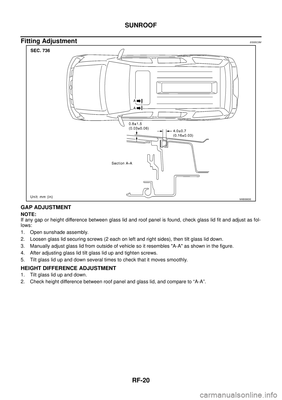
GAP ADJUSTMENT
NOTE:
If any gap or height difference between glass lid and roof panel is found, check glass lid fit and adjust as fol-
lows:
1. Open sunshade assembly.
2. Loosen glass lid securing screws (2 each on left and right sides), then tilt glass lid down.
3. Manually adjust glass lid from outside of vehicle so it resembles "A-A" as shown in the figure.
4. After adjusting glass lid tilt glass lid up and tighten screws.
5. Tilt glass lid up and down several times to check that it moves smoothly.
HEIGHT DIFFERENCE ADJUSTMENT
1. Tilt glass lid up and down.
2. Check height difference between roof panel and glass lid, and compare to “A-A”.
MIIB0883E
Page 2699 of 3171
RF-22
SUNROOF
lAfter any adjustment, check sunroof operation and glass lid alignment.
lHandle glass lid with care so not to cause damage.
lFor easier installation, mark each point before removal.
CAUTION:
lAlways work with a helper.
lBefore removal, fully close the glass lid assembly. Then, after removal, do not move the motor
assembly.
lAfter installing the sunroof and glass lid, check gap adjustment to ensure there is no malfunction.
SUNROOF UNIT
Removal
CAUTION:
lAlways work with a helper.
lWhen taking sunroof unit out, use shop cloths to protect the seats and trim from damage.
lAfter installing the sunroof unit and glass lid, be sure to check gap adjustment to ensure there is
no malfunction.
1. Remove headlining. Refer toEI-40, "
Removal and Installation".
2. Remove the sunroof glass lid. Refer toRF-22, "
GLASS LID".
3. Disconnect the drain hoses.
4. Remove the mounting nuts from the front end and side rail.
5. Remove the mounting bolts to sunroof bracket and then remove the sunroof unit.
Installation
1. Position the sunroof frame assembly and temporally tighten the mounting bolts to the sunroof brackets.
2. Tighten the mounting nuts to the front end and side rail.
3. Tighten the mounting bolts to sunroof brackets.
4. Connect the drain hoses.
5. Install the sunroof glass lid. Refer toRF-22, "
GLASS LID".
6. Install headlining. Refer toEI-40, "
Removal and Installation".
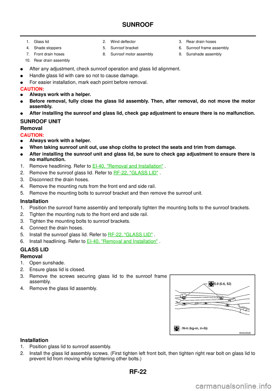
GLASS LID
Removal
1. Open sunshade.
2. Ensure glass lid is closed.
3. Remove the screws securing glass lid to the sunroof frame
assembly.
4. Remove the glass lid assembly.
Installation
1. Position glass lid to sunroof assembly.
2. Install the glass lid assembly screws. (First tighten left front bolt, then tighten right rear bolt on glass lid to
prevent lid from moving while tightening other bolts.)
1. Glass lid 2. Wind deflector 3. Rear drain hoses
4. Shade stoppers 5. Sunroof bracket 6. Sunroof frame assembly
7. Front drain hoses 8. Sunroof motor assembly 9. Sunshade assembly
10. Rear drain assembly
WIIA0252E
Page 2701 of 3171
RF-24
SUNROOF
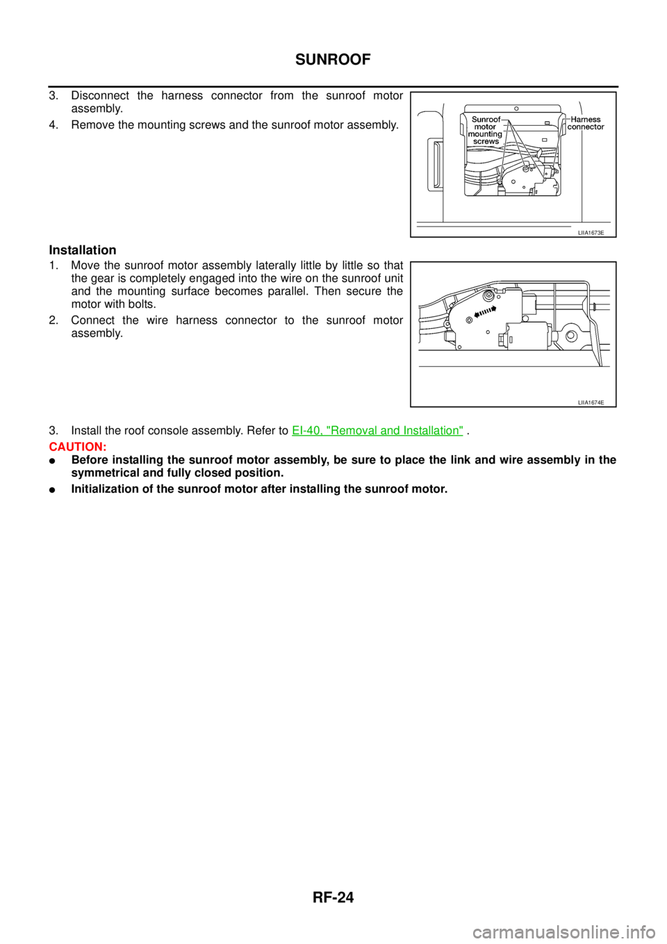
3. Disconnect the harness connector from the sunroof motor
assembly.
4. Remove the mounting screws and the sunroof motor assembly.
Installation
1. Move the sunroof motor assembly laterally little by little so that
the gear is completely engaged into the wire on the sunroof unit
and the mounting surface becomes parallel. Then secure the
motor with bolts.
2. Connect the wire harness connector to the sunroof motor
assembly.
3. Install the roof console assembly. Refer toEI-40, "
Removal and Installation".
CAUTION:
lBefore installing the sunroof motor assembly, be sure to place the link and wire assembly in the
symmetrical and fully closed position.
lInitialization of the sunroof motor after installing the sunroof motor.
LIIA1673E
LIIA1674E