2005 NISSAN NAVARA ECU
[x] Cancel search: ECUPage 2916 of 3171
SUPPLEMENTAL RESTRAINT SYSTEM (SRS)
SRS-7
C
D
E
F
G
I
J
K
L
MA
B
SRS
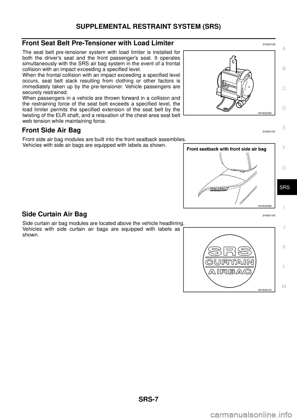
Front Seat Belt Pre-Tensioner with Load LimiterEHS001XB
The seat belt pre-tensioner system with load limiter is installed for
both the driver's seat and the front passenger's seat. It operates
simultaneously with the SRS air bag system in the event of a frontal
collision with an impact exceeding a specified level.
When the frontal collision with an impact exceeding a specified level
occurs, seat belt slack resulting from clothing or other factors is
immediately taken up by the pre-tensioner. Vehicle passengers are
securely restrained.
When passengers in a vehicle are thrown forward in a collision and
the restraining force of the seat belt exceeds a specified level, the
load limiter permits the specified extension of the seat belt by the
twisting of the ELR shaft, and a relaxation of the chest-area seat belt
web tension while maintaining force.
Front Side Air BagEHS001XC
Front side air bag modules are built into the front seatback assemblies.
Vehicles with side air bags are equipped with labels as shown.
Side Curtain Air BagEHS001XD
Side curtain air bag modules are located above the vehicle headlining.
Vehicles with side curtain air bags are equipped with labels as
shown.
WHIA0225E
WHIA0008E
WHIA0041E
Page 2925 of 3171
SRS-16
TROUBLE DIAGNOSIS
CONSULT-II Function (AIR BAG)
EHS001XK
CONSULT-II can display each diagnostic item using the diagnostic test modes shown following.
CONSULT-II FunctionEHS001XL
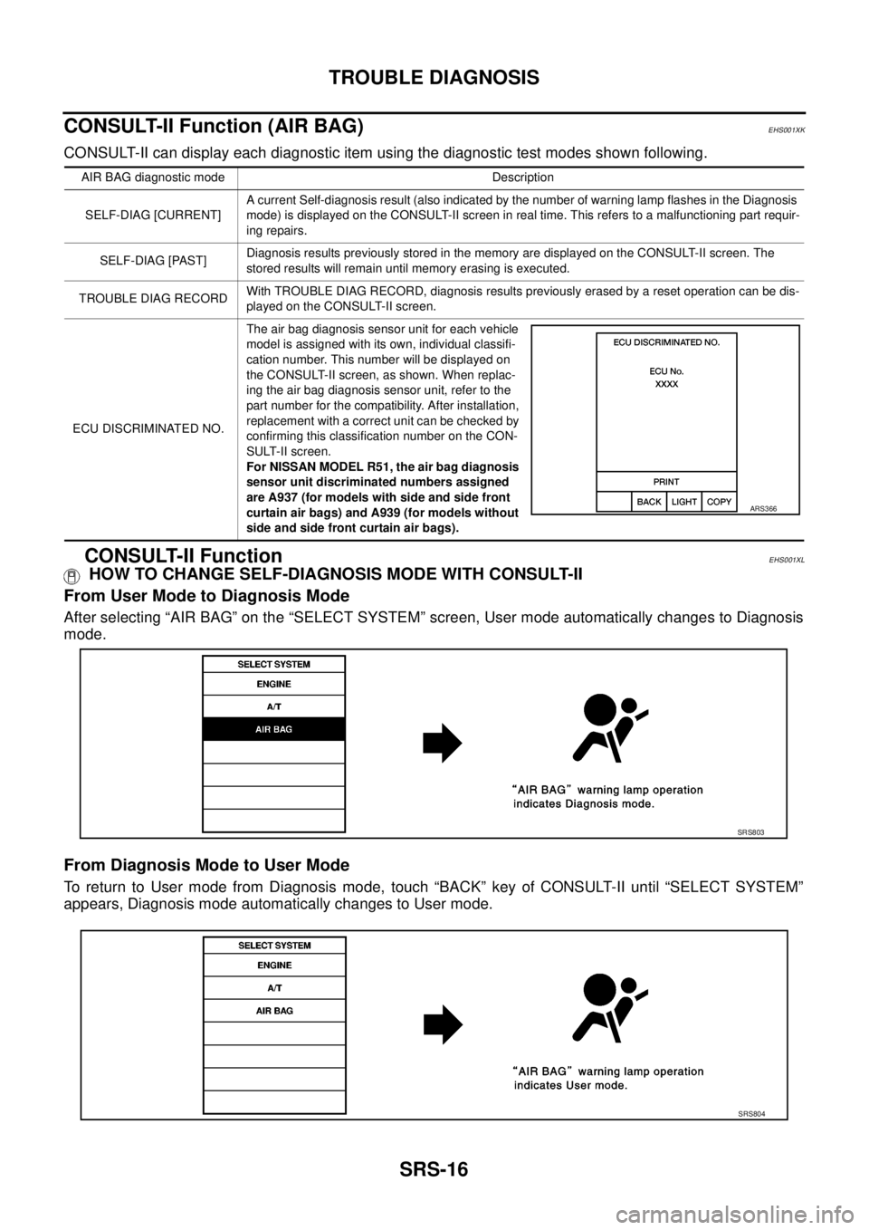
HOW TO CHANGE SELF-DIAGNOSIS MODE WITH CONSULT-II
From User Mode to Diagnosis Mode
After selecting “AIR BAG” on the “SELECT SYSTEM” screen, User mode automatically changes to Diagnosis
mode.
From Diagnosis Mode to User Mode
To return to User mode from Diagnosis mode, touch “BACK” key of CONSULT-II until “SELECT SYSTEM”
appears, Diagnosis mode automatically changes to User mode.
AIR BAG diagnostic mode Description
SELF-DIAG [CURRENT]A current Self-diagnosis result (also indicated by the number of warning lamp flashes in the Diagnosis
mode) is displayed on the CONSULT-II screen in real time. This refers to a malfunctioning part requir-
ing repairs.
SELF-DIAG [PAST]Diagnosis results previously stored in the memory are displayed on the CONSULT-II screen. The
stored results will remain until memory erasing is executed.
TROUBLE DIAG RECORDWith TROUBLE DIAG RECORD, diagnosis results previously erased by a reset operation can be dis-
played on the CONSULT-II screen.
ECU DISCRIMINATED NO.The air bag diagnosis sensor unit for each vehicle
model is assigned with its own, individual classifi-
cation number. This number will be displayed on
the CONSULT-II screen, as shown. When replac-
ing the air bag diagnosis sensor unit, refer to the
part number for the compatibility. After installation,
replacement with a correct unit can be checked by
confirming this classification number on the CON-
SULT-II screen.
For NISSAN MODEL R51, the air bag diagnosis
sensor unit discriminated numbers assigned
are A937 (for models with side and side front
curtain air bags) and A939 (for models without
side and side front curtain air bags).
ARS366
SRS803
SRS804
Page 2951 of 3171
SRS-42
FRONT PASSENGER AIR BAG MODULE
lBefore servicing SRS, turn the ignition switch off, disconnect both battery cables and wait at least
3 minutes.
lAlways work from the side of or under front passenger air bag module.
lAfter the work is completed, perform self-diagnosis to check that no malfunction is detected.
Refer toSRS-18, "
SRS Operation Check".
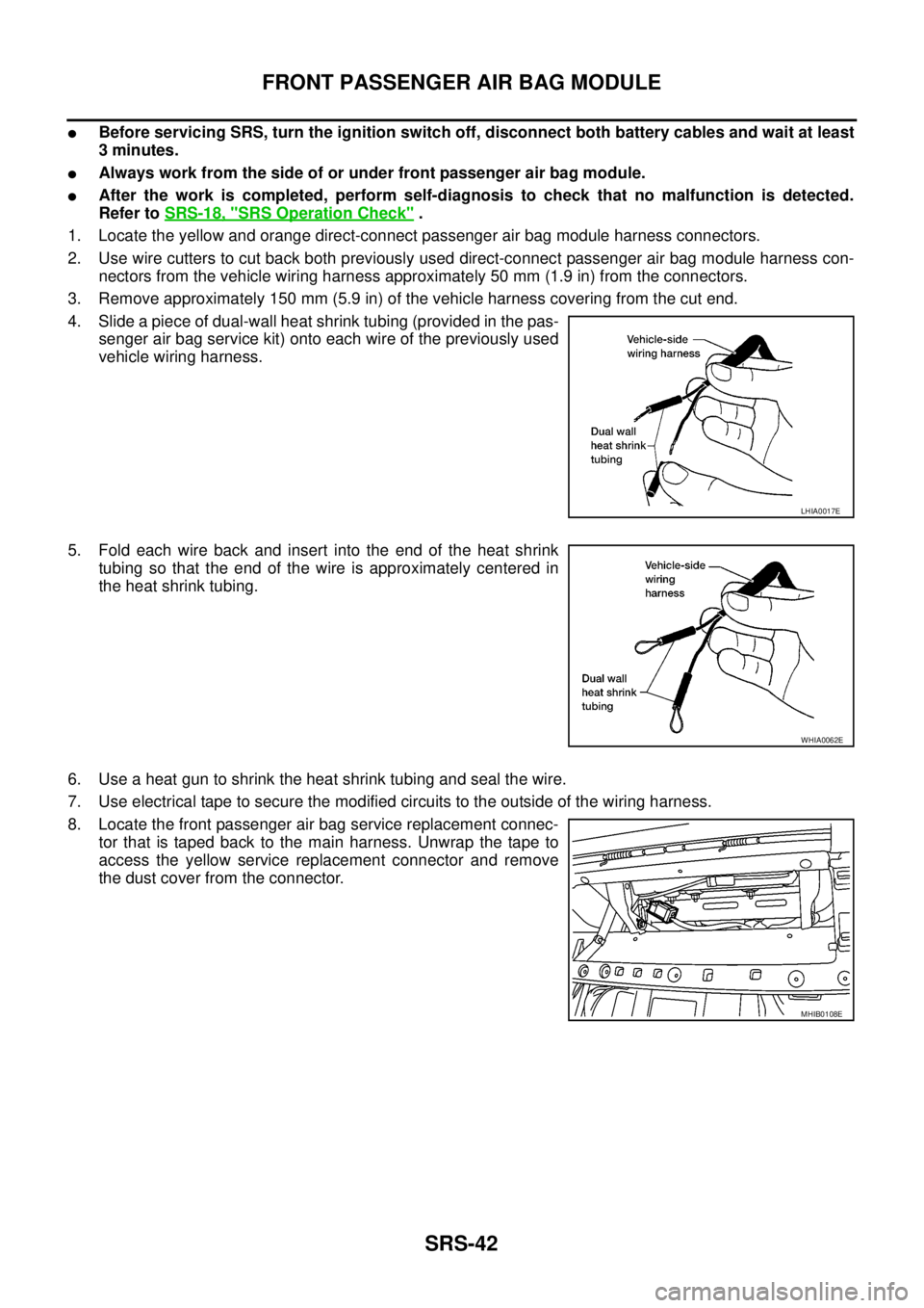
1. Locate the yellow and orange direct-connect passenger air bag module harness connectors.
2. Use wire cutters to cut back both previously used direct-connect passenger air bag module harness con-
nectors from the vehicle wiring harness approximately 50 mm (1.9 in) from the connectors.
3. Remove approximately 150 mm (5.9 in) of the vehicle harness covering from the cut end.
4. Slide a piece of dual-wall heat shrink tubing (provided in the pas-
senger air bag service kit) onto each wire of the previously used
vehicle wiring harness.
5. Fold each wire back and insert into the end of the heat shrink
tubing so that the end of the wire is approximately centered in
the heat shrink tubing.
6. Use a heat gun to shrink the heat shrink tubing and seal the wire.
7. Use electrical tape to secure the modified circuits to the outside of the wiring harness.
8. Locate the front passenger air bag service replacement connec-
tor that is taped back to the main harness. Unwrap the tape to
access the yellow service replacement connector and remove
the dust cover from the connector.
LHIA0017E
WHIA0062E
MHIB0108E
Page 2952 of 3171
FRONT SIDE AIR BAG MODULE
SRS-43
C
D
E
F
G
I
J
K
L
MA
B
SRS
FRONT SIDE AIR BAG MODULEPFP:K8EH0
Removal and InstallationEHS001XV
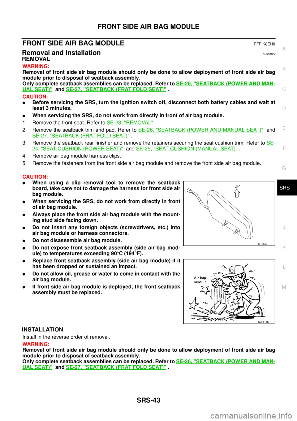
REMOVAL
WARNING:
Removal of front side air bag module should only be done to allow deployment of front side air bag
module prior to disposal of seatback assembly.
Only complete seatback assemblies can be replaced. Refer toSE-26, "
SEATBACK (POWER AND MAN-
UAL SEAT)"andSE-27, "SEATBACK (FRAT FOLD SEAT)".
CAUTION:
lBefore servicing the SRS, turn the ignition switch off, disconnect both battery cables and wait at
least 3 minutes.
lWhen servicing the SRS, do not work from directly in front of air bag module.
1. Remove the front seat. Refer toSE-23, "
REMOVAL".
2. Remove the seatback trim and pad. Refer toSE-26, "
SEATBACK (POWER AND MANUAL SEAT)"and
SE-27, "
SEATBACK (FRAT FOLD SEAT)".
3. Remove the seatback rear finisher and remove the retainers securing the seat cushion trim. Refer toSE-
24, "SEAT CUSHION (POWER SEAT)"andSE-25, "SEAT CUSHION (MANUAL SEAT)".
4. Remove air bag module harness clips.
5. Remove the fasteners from the front side air bag module and remove the front side air bag module.
CAUTION:
lWhen using a clip removal tool to remove the seatback
board, take care not to damage the harness for front side air
bag module.
lWhen servicing the SRS, do not work from directly in front
of air bag module.
lAlways place the front side air bag module with the mount-
ing stud side facing down.
lDo not insert any foreign objects (screwdrivers, etc.) into
air bag module or harness connectors.
lDo not disassemble air bag module.
lDo not expose front seatback assembly (side air bag mod-
ule) to temperatures exceeding 90°C(194°F).
lReplace front seatback assembly (side air bag module) if it
has been dropped or sustained an impact.
lDo not allow oil, grease or water to come in contact with the
air bag module.
lIf front side air bag module is deployed, the front seatback
assembly must be replaced.
INSTALLATION
Install in the reverse order of removal.
WARNING:
Removal of front side air bag module should only be done to allow deployment of front side air bag
module prior to disposal of seatback assembly.
Only complete seatback assemblies can be replaced. Refer toSE-26, "
SEATBACK (POWER AND MAN-
UAL SEAT)"andSE-27, "SEATBACK (FRAT FOLD SEAT)".
SRS623
SBF814E
Page 2957 of 3171
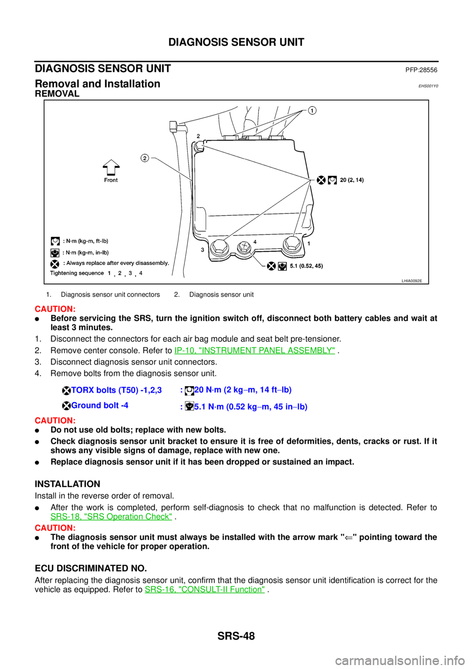
SRS-48
DIAGNOSIS SENSOR UNIT
DIAGNOSIS SENSOR UNIT
PFP:28556
Removal and InstallationEHS001Y0
REMOVAL
CAUTION:
lBefore servicing the SRS, turn the ignition switch off, disconnect both battery cables and wait at
least 3 minutes.
1. Disconnect the connectors for each air bag module and seat belt pre-tensioner.
2. Remove center console. Refer toIP-10, "
INSTRUMENT PANEL ASSEMBLY".
3. Disconnect diagnosis sensor unit connectors.
4. Remove bolts from the diagnosis sensor unit.
CAUTION:
lDo not use old bolts; replace with new bolts.
lCheck diagnosis sensor unit bracket to ensure it is free of deformities, dents, cracks or rust. If it
shows any visible signs of damage, replace with new one.
lReplace diagnosis sensor unit if it has been dropped or sustained an impact.
INSTALLATION
Install in the reverse order of removal.
lAfter the work is completed, perform self-diagnosis to check that no malfunction is detected. Refer to
SRS-18, "
SRS Operation Check".
CAUTION:
lThe diagnosis sensor unit must always be installed with the arrow mark "Ü" pointing toward the
front of the vehicle for proper operation.
ECU DISCRIMINATED NO.
After replacing the diagnosis sensor unit, confirm that the diagnosis sensor unit identification is correct for the
vehicle as equipped. Refer toSRS-16, "
CONSULT-II Function".
LHIA0092E
1. Diagnosis sensor unit connectors 2. Diagnosis sensor unit
TORX bolts (T50) -1,2,3:20N·m(2kg-m, 14 ft-lb)
Ground bolt -4
: 5.1 N·m (0.52 kg-m, 45 in-lb)
Page 2959 of 3171
SRS-50
DISPOSAL OF AIR BAG MODULE AND SEAT BELT PRE-TENSIONER
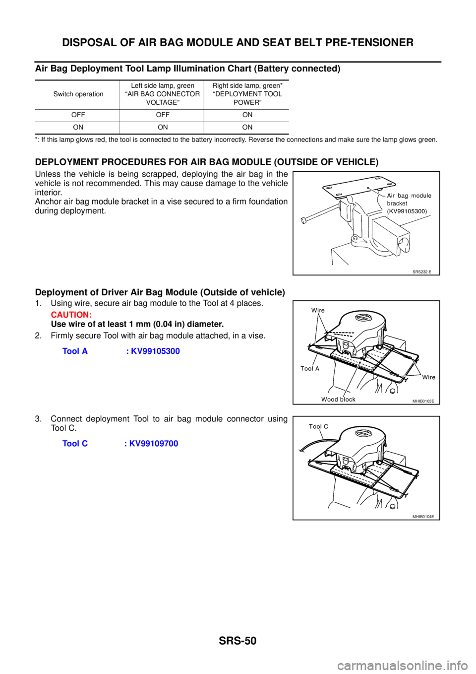
Air Bag Deployment Tool Lamp Illumination Chart (Battery connected)
*: If this lamp glows red, the tool is connected to the battery incorrectly. Reverse the connections and make sure the lamp glows green.
DEPLOYMENT PROCEDURES FOR AIR BAG MODULE (OUTSIDE OF VEHICLE)
Unless the vehicle is being scrapped, deploying the air bag in the
vehicle is not recommended. This may cause damage to the vehicle
interior.
Anchor air bag module bracket in a vise secured to a firm foundation
during deployment.
Deployment of Driver Air Bag Module (Outside of vehicle)
1. Using wire, secure air bag module to the Tool at 4 places.
CAUTION:
Use wire of at least 1 mm (0.04 in) diameter.
2. Firmly secure Tool with air bag module attached, in a vise.
3. Connect deployment Tool to air bag module connector using
To o l C .
Switch operationLeft side lamp, green
“AIR BAG CONNECTOR
VOLTAGE”Right side lamp, green*
“DEPLOYMENT TOOL
POWER”
OFF OFF ON
ON ON ON
SRS232-E
Tool A : KV99105300
MHIB0103E
Tool C : KV99109700
MHIB0104E
Page 2960 of 3171
DISPOSAL OF AIR BAG MODULE AND SEAT BELT PRE-TENSIONER
SRS-51
C
D
E
F
G
I
J
K
L
MA
B
SRS
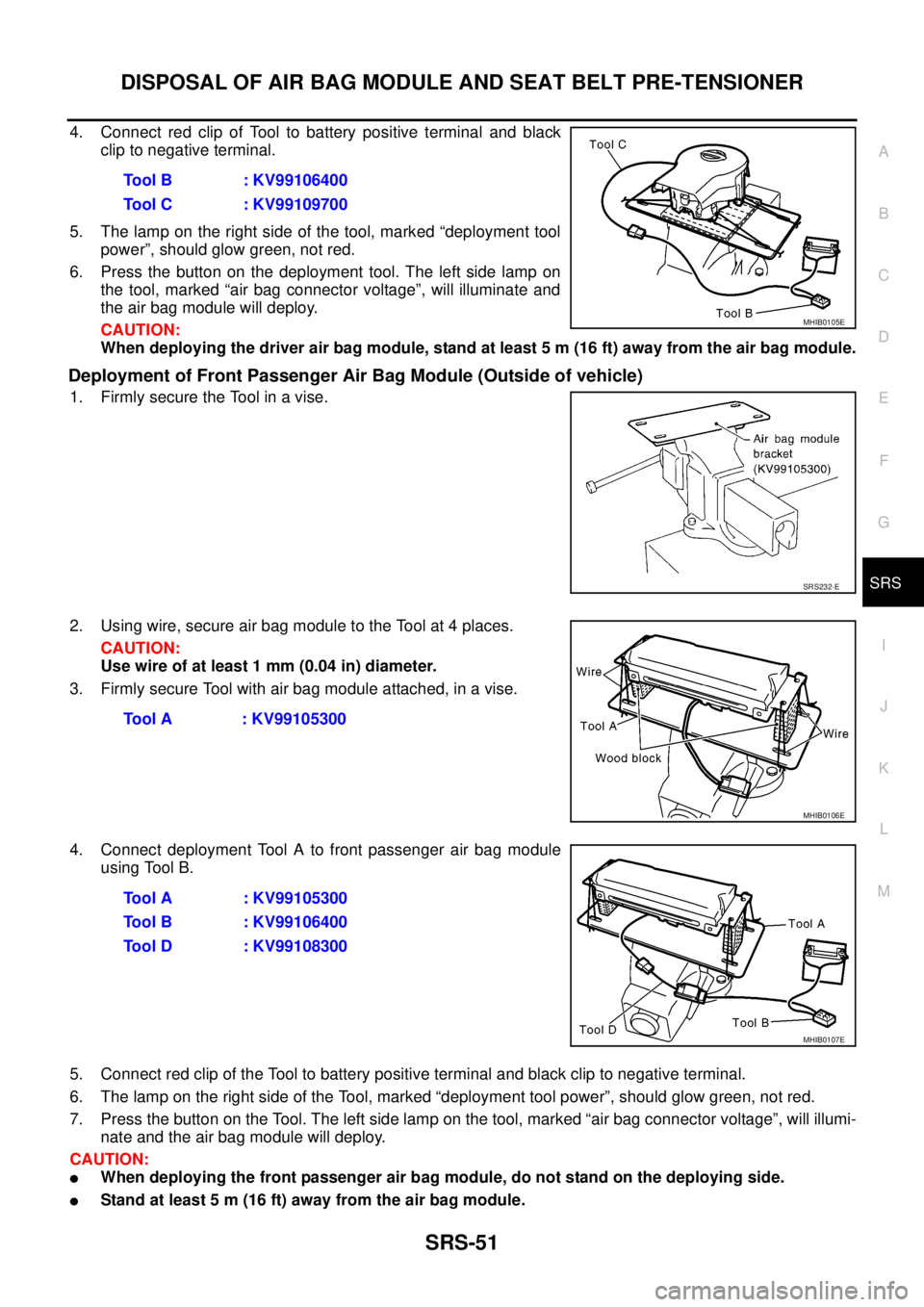
4. Connect red clip of Tool to battery positive terminal and black
clip to negative terminal.
5. The lamp on the right side of the tool, marked “deployment tool
power”, should glow green, not red.
6. Press the button on the deployment tool. The left side lamp on
the tool, marked “air bag connector voltage”, will illuminate and
the air bag module will deploy.
CAUTION:
When deploying the driver air bag module, stand at least 5 m (16 ft) away from the air bag module.
Deployment of Front Passenger Air Bag Module (Outside of vehicle)
1. Firmly secure the Tool in a vise.
2. Using wire, secure air bag module to the Tool at 4 places.
CAUTION:
Usewireofatleast1mm(0.04in)diameter.
3. Firmly secure Tool with air bag module attached, in a vise.
4. Connect deployment Tool A to front passenger air bag module
using Tool B.
5. Connect red clip of the Tool to battery positive terminal and black clip to negative terminal.
6. The lamp on the right side of the Tool, marked “deployment tool power”, should glow green, not red.
7. Press the button on the Tool. The left side lamp on the tool, marked “air bag connector voltage”, will illumi-
nate and the air bag module will deploy.
CAUTION:
lWhen deploying the front passenger air bag module, do not stand on the deploying side.
lStand at least 5 m (16 ft) away from the air bag module.Tool B : KV99106400
Tool C : KV99109700
MHIB0105E
SRS232-E
Tool A : KV99105300
MHIB0106E
Tool A : KV99105300
Tool B : KV99106400
Tool D : KV99108300
MHIB0107E
Page 2961 of 3171
SRS-52
DISPOSAL OF AIR BAG MODULE AND SEAT BELT PRE-TENSIONER
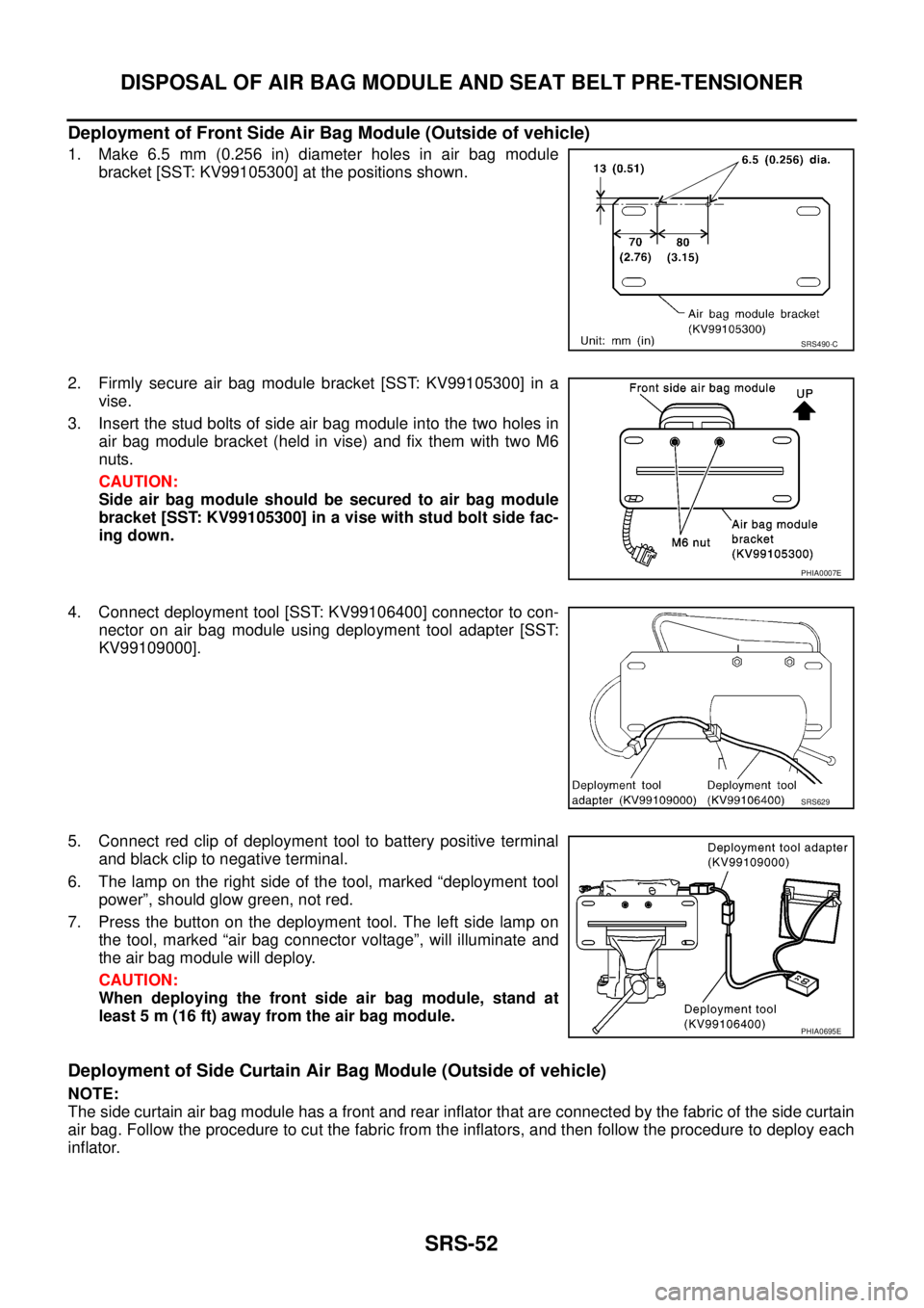
Deployment of Front Side Air Bag Module (Outside of vehicle)
1. Make 6.5 mm (0.256 in) diameter holes in air bag module
bracket [SST: KV99105300] at the positions shown.
2. Firmly secure air bag module bracket [SST: KV99105300] in a
vise.
3. Insert the stud bolts of side air bag module into the two holes in
air bag module bracket (held in vise) and fix them with two M6
nuts.
CAUTION:
Side air bag module should be secured to air bag module
bracket [SST: KV99105300] in a vise with stud bolt side fac-
ing down.
4. Connect deployment tool [SST: KV99106400] connector to con-
nector on air bag module using deployment tool adapter [SST:
KV99109000].
5. Connect red clip of deployment tool to battery positive terminal
and black clip to negative terminal.
6. The lamp on the right side of the tool, marked “deployment tool
power”, should glow green, not red.
7. Press the button on the deployment tool. The left side lamp on
the tool, marked “air bag connector voltage”, will illuminate and
the air bag module will deploy.
CAUTION:
When deploying the front side air bag module, stand at
least 5 m (16 ft) away from the air bag module.
Deployment of Side Curtain Air Bag Module (Outside of vehicle)
NOTE:
The side curtain air bag module has a front and rear inflator that are connected by the fabric of the side curtain
air bag. Follow the procedure to cut the fabric from the inflators, and then follow the procedure to deploy each
inflator.
SRS490-C
PHIA0007E
SRS629
PHIA0695E