2005 NISSAN NAVARA ECU
[x] Cancel search: ECUPage 1345 of 3171
SQUEAK AND RATTLE TROUBLE DIAGNOSES
EI-7
C
D
E
F
G
H
J
K
L
MA
B
EI
DUPLICATE THE NOISE AND TEST DRIVE
If possible, drive the vehicle with the customer until the noise is duplicated. Note any additional information on
the Diagnostic Worksheet regarding the conditions or location of the noise. This information can be used to
duplicate the same conditions when you confirm the repair.
If the noise can be duplicated easily during the test drive, to help identify the source of the noise, try to dupli-
cate the noise with the vehicle stopped by doing one or all of the following:
1) Close a door.
2) Tap or push/pull around the area where the noise appears to be coming from.
3) Rev the engine.
4) Use a floor jack to recreate vehicle “twist”.
5) At idle, apply engine load (electrical load, half-clutch on M/T model, drive position on A/T model).
6) Raisethevehicleonahoistandhitatirewitharubberhammer.
lDrive the vehicle and attempt to duplicate the conditions the customer states exist when the noise occurs.
lIf it is difficult to duplicate the noise, drive the vehicle slowly on an undulating or rough road to stress the
vehicle body.
CHECK RELATED SERVICE BULLETINS
After verifying the customer concern or symptom, check ASIST for Technical Service Bulletins (TSBs) related
to that concern or symptom.
If a TSB relates to the symptom, follow the procedure to repair the noise.
LOCATE THE NOISE AND IDENTIFY THE ROOT CAUSE
1. Narrow down the noise to a general area.To help pinpoint the source of the noise, use a listening tool
(Engine Ear and mechanic's stethoscope).
2. Narrow down the noise to a more specific area and identify the cause of the noise by:
lremoving the components in the area that you suspect the noise is coming from.
Do not use too much force when removing clips and fasteners, otherwise clips and fasteners can be bro-
ken or lost during the repair, resulting in the creation of new noise.
ltapping or pushing/pulling the component that you suspect is causing the noise.
Do not tap or push/pull the component with excessive force, otherwise the noise will be eliminated only
temporarily.
lfeeling for a vibration with your hand by touching the component(s) that you suspect is (are) causing the
noise.
lplacing a piece of paper between components that you suspect are causing the noise.
llooking for loose components and contact marks.
Refer toEI-7, "
Generic Squeak and Rattle Troubleshooting".
REPAIR THE CAUSE
lIf the cause is a loose component, tighten the component securely.
lIf the cause is insufficient clearance between components:
–separate components by repositioning or loosening and retightening the component, if possible.
–insulate components with a suitable insulator such as urethane pads, foam blocks, felt cloth tape or ure-
thane tape.
CAUTION:
Do not use excessive force as many components are constructed of plastic and may be damaged.
Always check with the Parts Department for the latest parts information.
CONFIRM THE REPAIR
Confirm that the cause of a noise is repaired by test driving the vehicle. Operate the vehicle under the same
conditions as when the noise originally occurred. Refer to the notes on the Diagnostic Worksheet.
Generic Squeak and Rattle TroubleshootingEIS00DY6
Refer to Table of Contents for specific component removal and installation information.
INSTRUMENT PANEL
Most incidents are caused by contact and movement between:
1. The cluster lid A and instrument panel
2. Acrylic lens and combination meter housing
Page 1346 of 3171
EI-8
SQUEAK AND RATTLE TROUBLE DIAGNOSES
3. Instrument panel to front pillar garnish
4. Instrument panel to windshield
5. Instrument panel mounting pins
6. Wiring harnesses behind the combination meter
7. A/C defroster duct and duct joint
These incidents can usually be located by tapping or moving the components to duplicate the noise or by
pressing on the components while driving to stop the noise. Most of these incidents can be repaired by apply-
ing felt cloth tape or silicone spray (in hard to reach areas). Urethane pads can be used to insulate wiring har-
ness.
CAUTION:
Do not use silicone spray to isolate a squeak or rattle. If you saturate the area with silicone, you will
not be able to recheck the repair.
CENTER CONSOLE
Components to pay attention to include:
1. Shifter assembly cover to finisher
2. A/C control unit and cluster lid C
3. Wiring harnesses behind audio and A/C control unit
The instrument panel repair and isolation procedures also apply to the center console.
DOORS
Pay attention to the:
1. Finisher and inner panel making a slapping noise
2. Inside handle escutcheon to door finisher
3. Wiring harnesses tapping
4. Door striker out of alignment causing a popping noise on starts and stops
Tapping or moving the components or pressing on them while driving to duplicate the conditions can isolate
many of these incidents.
TRUNK
Trunk noises are often caused by a loose jack or loose items put into the trunk by the owner.
In addition look for:
1. Trunk lid bumpers out of adjustment
2. Trunk lid striker out of adjustment
3. The trunk lid torsion bars knocking together
4. A loose license plate or bracket
Most of these incidents can be repaired by adjusting, securing or insulating the item(s) or component(s) caus-
ing the noise.
SUNROOF/HEADLINING
Noises in the sunroof/headlining area can often be traced to one of the following:
1. Sunroof lid, rail, linkage or seals making a rattle or light knocking noise
2. Sun visor shaft shaking in the holder
3. Front or rear windshield touching headliner and squeaking
Again, pressing on the components to stop the noise while duplicating the conditions can isolate most of these
incidents. Repairs usually consist of insulating with felt cloth tape.
OVERHEAD CONSOLE (FRONT AND REAR)
Overhead console noises are often caused by the console panel clips not being engaged correctly. Most of
these incidents are repaired by pushing up on the console at the clip locations until the clips engage.
In addition look for:
1. Loose harness or harness connectors.
2. Front console map/reading lamp lens loose.
3. Loose screws at console attachment points.
Page 1347 of 3171
SQUEAK AND RATTLE TROUBLE DIAGNOSES
EI-9
C
D
E
F
G
H
J
K
L
MA
B
EI
SEATS
When isolating seat noise it's important to note the position the seat is in and the load placed on the seat when
the noise is present. These conditions should be duplicated when verifying and isolating the cause of the
noise.
Cause of seat noise include:
1. Headrest rods and holder
2. A squeak between the seat pad cushion and frame
3. The rear seatback lock and bracket
These noises can be isolated by moving or pressing on the suspected components while duplicating the con-
ditions under which the noise occurs. Most of these incidents can be repaired by repositioning the component
or applying urethane tape to the contact area.
UNDERHOOD
Some interior noise may be caused by components under the hood or on the engine wall. The noise is then
transmitted into the passenger compartment.
Causes of transmitted underhood noise include:
1. Any component mounted to the engine wall
2. Components that pass through the engine wall
3. Engine wall mounts and connectors
4. Loose radiator mounting pins
5. Hood bumpers out of adjustment
6. Hood striker out of adjustment
These noises can be difficult to isolate since they cannot be reached from the interior of the vehicle. The best
method is to secure, move or insulate one component at a time and test drive the vehicle. Also, engine RPM
or load can be changed to isolate the noise. Repairs can usually be made by moving, adjusting, securing, or
insulating the component causing the noise.
Page 1367 of 3171
SIDE GUARD MOLDING
EI-29
C
D
E
F
G
H
J
K
L
MA
B
EI
REMOVAL
CAUTION:
Never apply tack-paper adhesive remover to body panel surface finished with lacquer-based paints.
lOriginal side guard molding is affixed to body panel with double-faced adhesive tape.
1. Heat molding to between 30°and 40°C(86°to 104°F) with a heat gun.
2. Raise end of molding and cut away tape to remove molding. Remove all traces of tape.
INSTALLATION
lOn vehicles coated with Hard Clear Coat, use double-faced 3M adhesive tape Product No. 4210 or equiv-
alent, after priming with 3M primer Product No. N200, C-100 or equivalent.
lThe repair parts are also affixed with double-faced adhesive tape.
lTo re-use existing molding, clean all traces of double sided tape from the molding and apply new double-
facedtapetothemolding.
1. Clean the panel surface with isopropyl alcohol or equivalent to degrease the surface.
2. Heat the panel and molding tape surface to 30°to 40°C(86°to 104°F).
3. Remove the backing sheet from the tape surface.
lAlign the locating pin into the hole in the outer door.
lContinue aligning the pins into their corresponding holes in the outer door during installation.
4. Press ends by hand and use a roller to apply 5 kg-f (11 lbs-f) to press molding to door surface.
lApply even pressure along molding to insure proper wet out.
CAUTION:
To secure contact, do not wash vehicle for 24 hours after installation.
Page 1419 of 3171
OIL PAN AND OIL STRAINER
EM-37
C
D
E
F
G
H
I
J
K
L
MA
EM
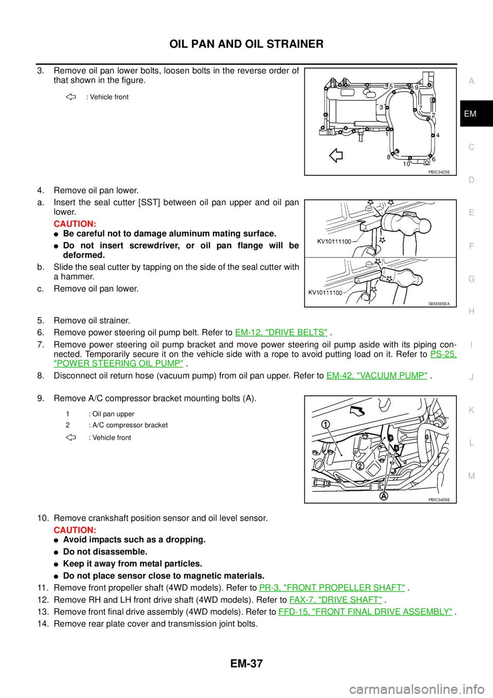
3. Remove oil pan lower bolts, loosen bolts in the reverse order of
that shown in the figure.
4. Remove oil pan lower.
a. Insert the seal cutter [SST] between oil pan upper and oil pan
lower.
CAUTION:
lBe careful not to damage aluminum mating surface.
lDo not insert screwdriver, or oil pan flange will be
deformed.
b. Slide the seal cutter by tapping on the side of the seal cutter with
a hammer.
c. Remove oil pan lower.
5. Remove oil strainer.
6. Remove power steering oil pump belt. Refer toEM-12, "
DRIVE BELTS".
7. Remove power steering oil pump bracket and move power steering oil pump aside with its piping con-
nected. Temporarily secure it on the vehicle side with a rope to avoid putting load on it. Refer toPS-25,
"POWER STEERING OIL PUMP".
8. Disconnect oil return hose (vacuum pump) from oil pan upper. Refer toEM-42, "
VACUUM PUMP".
9. Remove A/C compressor bracket mounting bolts (A).
10. Remove crankshaft position sensor and oil level sensor.
CAUTION:
lAvoid impacts such as a dropping.
lDo not disassemble.
lKeep it away from metal particles.
lDo not place sensor close to magnetic materials.
11. Remove front propeller shaft (4WD models). Refer toPR-3, "
FRONT PROPELLER SHAFT".
12. Remove RH and LH front drive shaft (4WD models). Refer toFAX-7, "
DRIVE SHAFT".
13. Remove front final drive assembly (4WD models). Refer toFFD-15, "
FRONT FINAL DRIVE ASSEMBLY".
14. Remove rear plate cover and transmission joint bolts.
: Vehicle front
PBIC3425E
SEM365EA
1 : Oil pan upper
2 : A/C compressor bracket
: Vehicle front
PBIC3426E
Page 1443 of 3171
CAMSHAFT
EM-61
C
D
E
F
G
H
I
J
K
L
MA
EM
Camshaft Runout
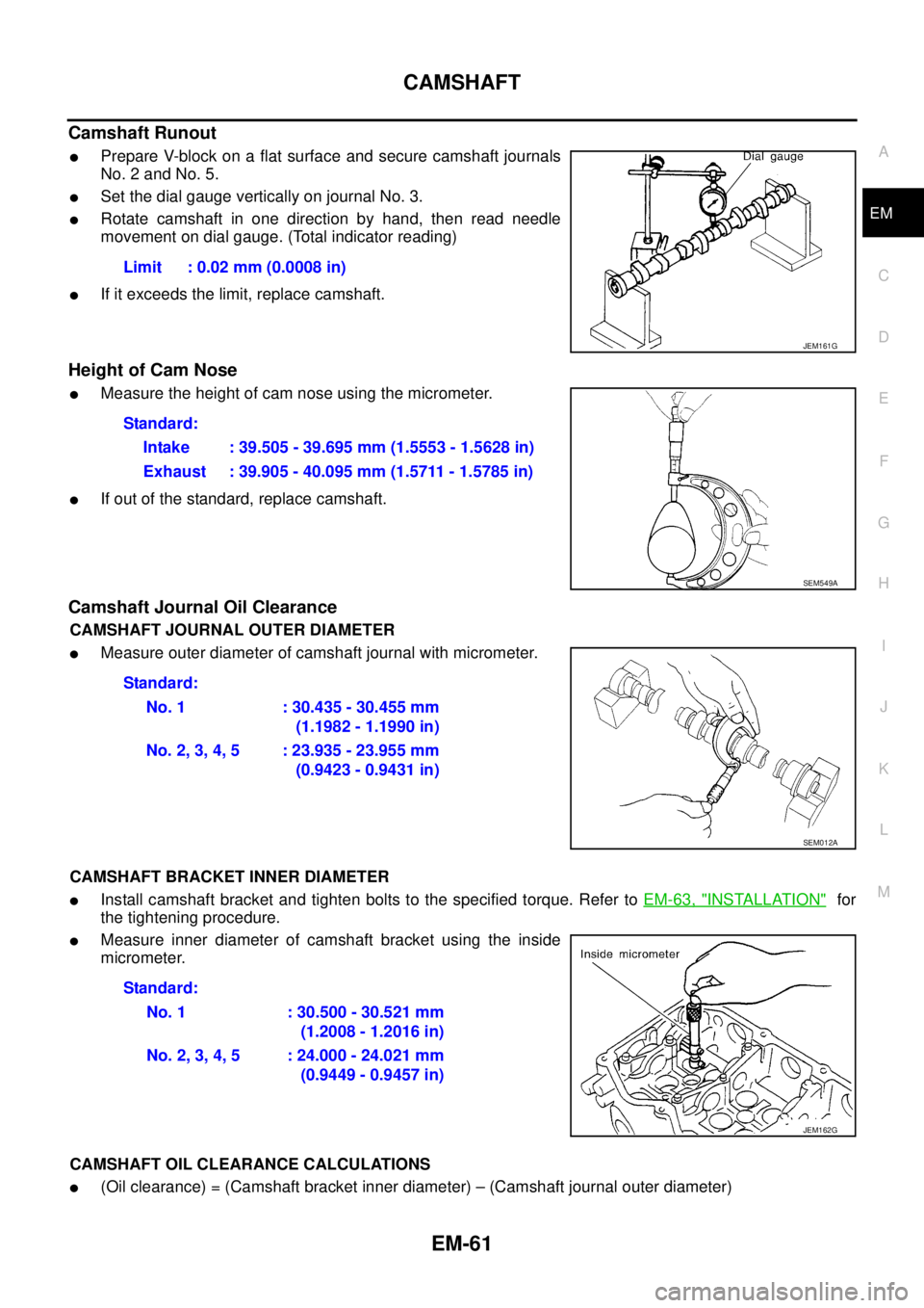
lPrepare V-block on a flat surface and secure camshaft journals
No. 2 and No. 5.
lSet the dial gauge vertically on journal No. 3.
lRotate camshaft in one direction by hand, then read needle
movement on dial gauge. (Total indicator reading)
lIf it exceeds the limit, replace camshaft.
Height of Cam Nose
lMeasure the height of cam nose using the micrometer.
lIf out of the standard, replace camshaft.
Camshaft Journal Oil Clearance
CAMSHAFT JOURNAL OUTER DIAMETER
lMeasure outer diameter of camshaft journal with micrometer.
CAMSHAFT BRACKET INNER DIAMETER
lInstall camshaft bracket and tighten bolts to the specified torque. Refer toEM-63, "INSTALLATION"for
the tightening procedure.
lMeasure inner diameter of camshaft bracket using the inside
micrometer.
CAMSHAFT OIL CLEARANCE CALCULATIONS
l(Oil clearance) = (Camshaft bracket inner diameter) – (Camshaft journal outer diameter)Limit : 0.02 mm (0.0008 in)
JEM161G
Standard:
Intake : 39.505 - 39.695 mm (1.5553 - 1.5628 in)
Exhaust : 39.905 - 40.095 mm (1.5711 - 1.5785 in)
SEM549A
Standard:
No. 1 : 30.435 - 30.455 mm
(1.1982 - 1.1990 in)
No.2,3,4,5 :23.935-23.955mm
(0.9423 - 0.9431 in)
SEM012A
Standard:
No. 1 : 30.500 - 30.521 mm
(1.2008 - 1.2016 in)
No.2,3,4,5 :24.000-24.021mm
(0.9449 - 0.9457 in)
JEM162G
Page 1446 of 3171
EM-64
CAMSHAFT
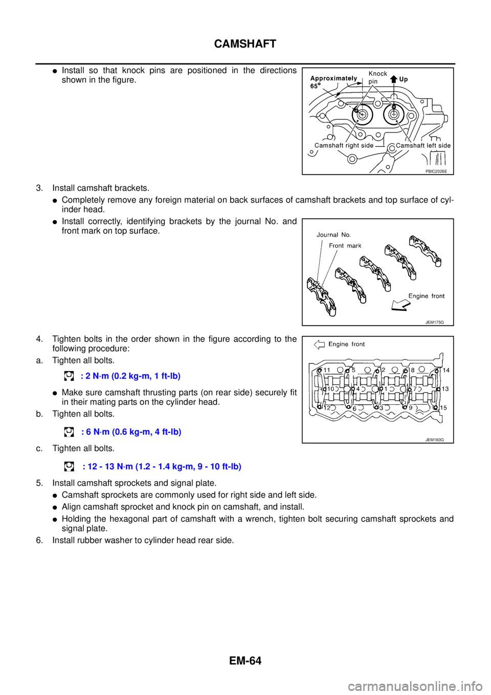
lInstall so that knock pins are positioned in the directions
showninthefigure.
3. Install camshaft brackets.
lCompletely remove any foreign material on back surfaces of camshaft brackets and top surface of cyl-
inder head.
lInstall correctly, identifying brackets by the journal No. and
front mark on top surface.
4. Tighten bolts in the order shown in the figure according to the
following procedure:
a. Tighten all bolts.
lMake sure camshaft thrusting parts (on rear side) securely fit
in their mating parts on the cylinder head.
b. Tighten all bolts.
c. Tighten all bolts.
5. Install camshaft sprockets and signal plate.
lCamshaft sprockets are commonly used for right side and left side.
lAlign camshaft sprocket and knock pin on camshaft, and install.
lHolding the hexagonal part of camshaft with a wrench, tighten bolt securing camshaft sprockets and
signal plate.
6. Install rubber washer to cylinder head rear side.
PBIC2026E
JEM175G
:2N·m(0.2kg-m,1ft-lb)
:6N·m(0.6kg-m,4ft-lb)
:12-13N·m(1.2-1.4kg-m,9-10ft-lb)
JEM160G
Page 1450 of 3171
![NISSAN NAVARA 2005 Repair Workshop Manual EM-68
CAMSHAFT
4. Withvalvespringinacompressedstate,removethecamshaft
pliers [SST] by securely setting the outer circumference of the
valve lifter with the end of the lifter stopper [SST].
lHold the l NISSAN NAVARA 2005 Repair Workshop Manual EM-68
CAMSHAFT
4. Withvalvespringinacompressedstate,removethecamshaft
pliers [SST] by securely setting the outer circumference of the
valve lifter with the end of the lifter stopper [SST].
lHold the l](/manual-img/5/57362/w960_57362-1449.png)
EM-68
CAMSHAFT
4. Withvalvespringinacompressedstate,removethecamshaft
pliers [SST] by securely setting the outer circumference of the
valve lifter with the end of the lifter stopper [SST].
lHold the lifter stopper by hand until the shim is removed.
CAUTION:
Do not retrieve the camshaft pliers forcefully, as cam-
shaft will be damaged.
5. Move the round hole of adjusting shim to the front with the very
thin screwdriver or like that.
lWhen adjusting shim on valve lifter will not rotate smoothly,
restart from step 3 to release the end of the lifter stopper
[SST] from touching adjusting shim.
6. Remove adjusting shim from valve lifter by blowing air through
the round hole of the adjusting shim with the air gun.
CAUTION:
To prevent any remaining engine oil from being blown
around, thoroughly wipe the area clean and wear protective
goggles.
7. Remove adjusting shim by using the magnet hand.
8. Measure the thickness of adjusting shim using the micrometer.
lMeasure near the center of the shim (the part that touches
camshaft).
9. Select the new adjusting shim from the following methods.
PBIC2322E
PBIC2323E
PBIC2324E
FEM032
Calculation method of the adjusting shim thickness:
R = Thickness of removed shim
N = Thickness of new shim
M = Measured valve clearance
Intake
N=R+[M-0.28mm(0.0010in)]
Exhaust
N=R+[M-0.30mm(0.0118in)]