2005 NISSAN NAVARA ECU
[x] Cancel search: ECUPage 770 of 3171
BL-186
NATS(NISSAN ANTI-THEFT SYSTEM)
3.CHECK SECURITY INDICATOR OPERATION
1. Turn ignition switch OFF.
2. Disconnect BCM and combination meter connector.
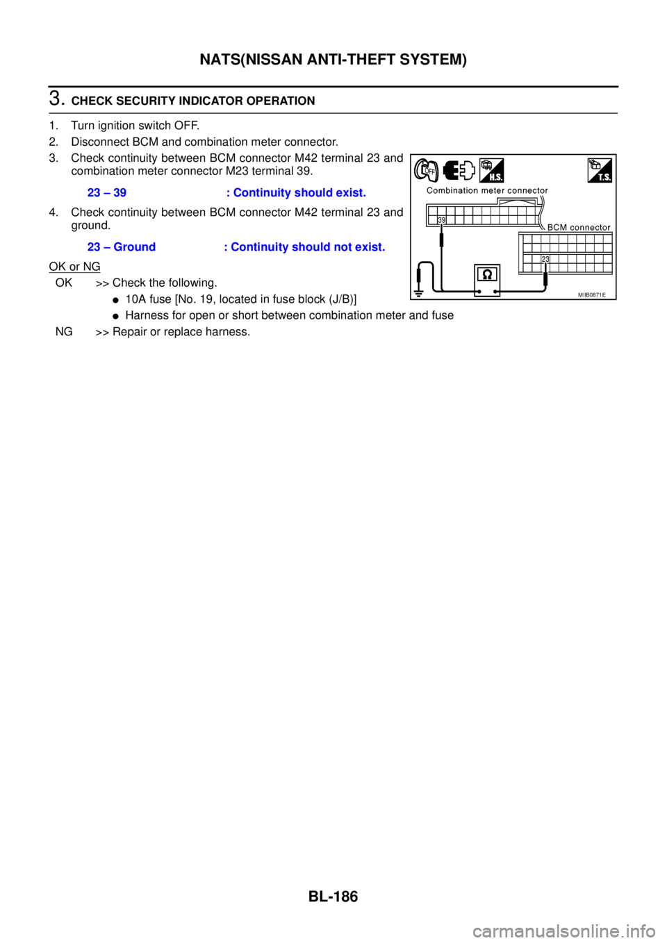
3. Check continuity between BCM connector M42 terminal 23 and
combination meter connector M23 terminal 39.
4. Check continuity between BCM connector M42 terminal 23 and
ground.
OK or NG
OK >> Check the following.
l10A fuse [No. 19, located in fuse block (J/B)]
lHarness for open or short between combination meter and fuse
NG >> Repair or replace harness.23 – 39 : Continuity should exist.
23 – Ground : Continuity should not exist.
MIIB0871E
Page 793 of 3171
BRAKE PEDAL
BR-7
C
D
E
G
H
I
J
K
L
MA
B
BR
ADJUSTMENT
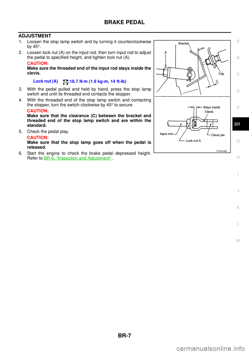
1. Loosen the stop lamp switch and by turning it counterclockwise
by 45°.
2. Loosen lock nut (A) on the input rod, then turn input rod to adjust
the pedal to specified height, and tighten lock nut (A).
CAUTION:
Make sure the threaded end of the input rod stays inside the
clevis.
3. With the pedal pulled and held by hand, press the stop lamp
switch and until its threaded end contacts the stopper.
4. With the threaded end of the stop lamp switch and contacting
the stopper, turn the switch clockwise by 45°to secure.
CAUTION:
Make sure that the clearance (C) between the bracket and
threaded end of the stop lamp switch and are within the
standard.
5. Check the pedal play.
CAUTION:
Make sure that the stop lamp goes off when the pedal is
released.
6. Start the engine to check the brake pedal depressed height.
Refer toBR-6, "
Inspection and Adjustment". Lock nut (A)
:18.7 N·m (1.9 kg-m, 14 ft-lb)
PFIA0436E
Page 799 of 3171
BRAKE TUBE AND HOSE
BR-13
C
D
E
G
H
I
J
K
L
MA
B
BR
CAUTION:
lAll brake tubes and hoses must be free from excessive bending, twisting and pulling.
lMake sure that there is no interference with other parts when turning steering both clockwise and
counterclockwise.
lBrake tube and hose is an important safety part. Always disassemble the parts and retighten their
fittings, if a brake fluid leak is detected. Replace applicable part with a new one, if damaged part is
detected.
lBe careful not to splash brake fluid on painted areas; it may cause paint damage. If brake fluid is
splashed on painted surfaces of body, immediately wipe off them and wash it away with water.
lDo not bend or twist brake hose sharply, or strongly pull it.
lCover the open end of brake tube and hoses when disconnecting to prevent entrance of dirt.
lRefill with new brake fluid “DOT 3” or “DOT 4”.
lNever reuse drained brake fluid.
Removal and Installation of Front Brake Tube and Brake HoseEFS005SM
REMOVAL
1. Drain brake fluid. Refer toBR-10, "Drain and Refill".
2. Using a flare nut wrench, disconnect brake tube from brake hose.
3. Remove union bolt and remove brake hose from caliper assembly.
4. Remove lock plate and remove brake hose from vehicle.
INSTALLATION
1. Assemble the union bolt and copper washers to the brake hose.
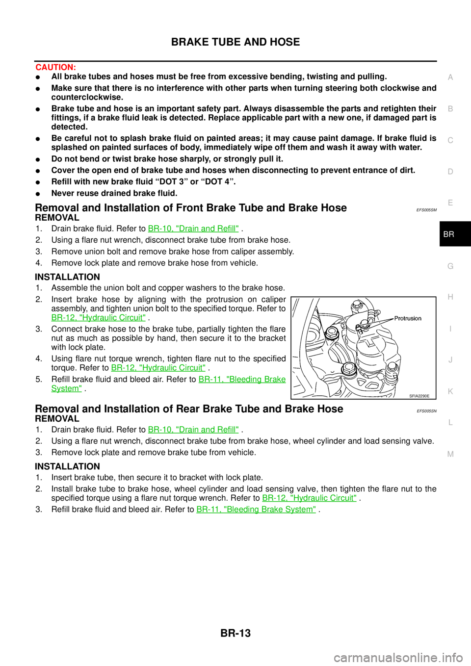
2. Insert brake hose by aligning with the protrusion on caliper
assembly, and tighten union bolt to the specified torque. Refer to
BR-12, "
Hydraulic Circuit".
3. Connect brake hose to the brake tube, partially tighten the flare
nut as much as possible by hand, then secure it to the bracket
with lock plate.
4. Using flare nut torque wrench, tighten flare nut to the specified
torque. Refer toBR-12, "
Hydraulic Circuit".
5. Refill brake fluid and bleed air. Refer toBR-11, "
Bleeding Brake
System".
Removal and Installation of Rear Brake Tube and Brake HoseEFS005SN
REMOVAL
1. Drain brake fluid. Refer toBR-10, "Drain and Refill".
2. Using a flare nut wrench, disconnect brake tube from brake hose, wheel cylinder and load sensing valve.
3. Remove lock plate and remove brake tube from vehicle.
INSTALLATION
1. Insert brake tube, then secure it to bracket with lock plate.
2. Install brake tube to brake hose, wheel cylinder and load sensing valve, then tighten the flare nut to the
specified torque using a flare nut torque wrench. Refer toBR-12, "
Hydraulic Circuit".
3. Refill brake fluid and bleed air. Refer toBR-11, "
Bleeding Brake System".
SFIA2290E
Page 807 of 3171
BRAKE BOOSTER
BR-21
C
D
E
G
H
I
J
K
L
MA
B
BR
INSTALLATION
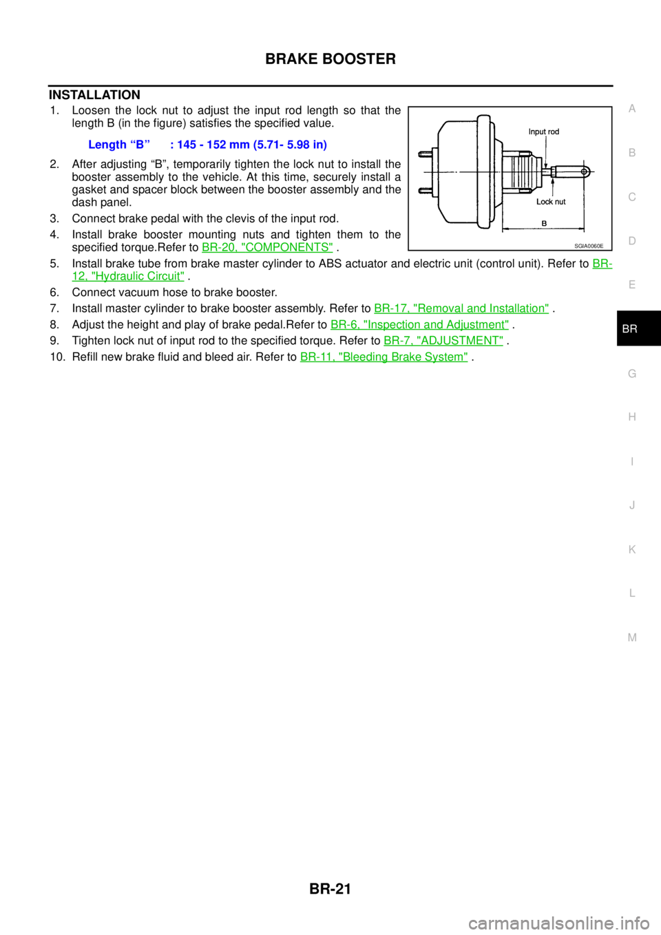
1. Loosen the lock nut to adjust the input rod length so that the
length B (in the figure) satisfies the specified value.
2. After adjusting “B”, temporarily tighten the lock nut to install the
booster assembly to the vehicle. At this time, securely install a
gasket and spacer block between the booster assembly and the
dash panel.
3. Connect brake pedal with the clevis of the input rod.
4. Install brake booster mounting nuts and tighten them to the
specified torque.Refer toBR-20, "
COMPONENTS".
5. Install brake tube from brake master cylinder to ABS actuator and electric unit (control unit). Refer toBR-
12, "Hydraulic Circuit".
6. Connect vacuum hose to brake booster.
7. Install master cylinder to brake booster assembly. Refer toBR-17, "
Removal and Installation".
8. Adjust the height and play of brake pedal.Refer toBR-6, "
Inspection and Adjustment".
9. Tighten lock nut of input rod to the specified torque. Refer toBR-7, "
ADJUSTMENT".
10. Refill new brake fluid and bleed air. Refer toBR-11, "
Bleeding Brake System". Length“B” :145-152mm(5.71-5.98in)
SGIA0060E
Page 814 of 3171
BR-28
FRONT DISC BRAKE
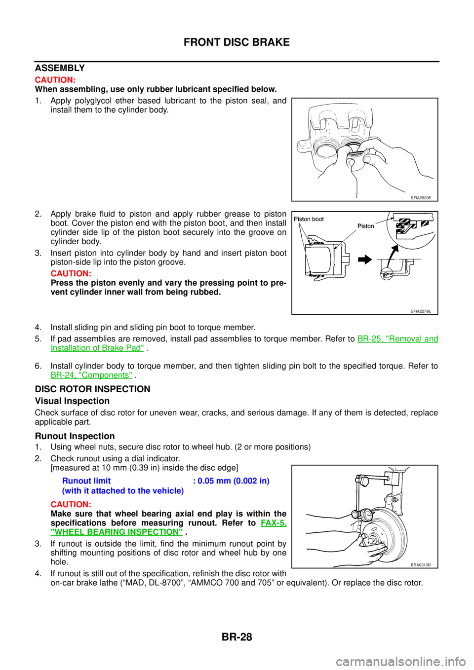
ASSEMBLY
CAUTION:
When assembling, use only rubber lubricant specified below.
1. Apply polyglycol ether based lubricant to the piston seal, and
install them to the cylinder body.
2. Apply brake fluid to piston and apply rubber grease to piston
boot.Coverthepistonendwiththepistonboot,andtheninstall
cylinder side lip of the piston boot securely into the groove on
cylinder body.
3. Insert piston into cylinder body by hand and insert piston boot
piston-side lip into the piston groove.
CAUTION:
Press the piston evenly and vary the pressing point to pre-
vent cylinder inner wall from being rubbed.
4. Install sliding pin and sliding pin boot to torque member.
5. If pad assemblies are removed, install pad assemblies to torque member. Refer toBR-25, "
Removal and
Installation of Brake Pad".
6. Install cylinder body to torque member, and then tighten sliding pin bolt to the specified torque. Refer to
BR-24, "
Components".
DISC ROTOR INSPECTION
Visual Inspection
Check surface of disc rotor for uneven wear, cracks, and serious damage. If any of them is detected, replace
applicable part.
Runout Inspection
1. Using wheel nuts, secure disc rotor to wheel hub. (2 or more positions)
2. Check runout using a dial indicator.
[measured at 10 mm (0.39 in) inside the disc edge]
CAUTION:
Make sure that wheel bearing axial end play is within the
specifications before measuring runout. Refer toFAX-5,
"WHEEL BEARING INSPECTION".
3. If runout is outside the limit, find the minimum runout point by
shifting mounting positions of disc rotor and wheel hub by one
hole.
4. If runout is still out of the specification, refinish the disc rotor with
on-car brake lathe (“MAD, DL-8700”, “AMMCO 700 and 705” or equivalent). Or replace the disc rotor.
SFIA2920E
SFIA2279E
Runout limit
(with it attached to the vehicle):0.05mm(0.002in)
BRA0013D
Page 839 of 3171
![NISSAN NAVARA 2005 Repair Workshop Manual TROUBLE DIAGNOSIS
BRC-17
[ABS]
C
D
E
G
H
I
J
K
L
MA
B
BRC
CONSULT- II FunctionsEFS005TT
CONSULT-II MAIN FUNCTION
In a diagnosis function (main function), there are “SELF-DIAG RESULTS”, “DATA MON NISSAN NAVARA 2005 Repair Workshop Manual TROUBLE DIAGNOSIS
BRC-17
[ABS]
C
D
E
G
H
I
J
K
L
MA
B
BRC
CONSULT- II FunctionsEFS005TT
CONSULT-II MAIN FUNCTION
In a diagnosis function (main function), there are “SELF-DIAG RESULTS”, “DATA MON](/manual-img/5/57362/w960_57362-838.png)
TROUBLE DIAGNOSIS
BRC-17
[ABS]
C
D
E
G
H
I
J
K
L
MA
B
BRC
CONSULT- II FunctionsEFS005TT
CONSULT-II MAIN FUNCTION
In a diagnosis function (main function), there are “SELF-DIAG RESULTS”, “DATA MONITOR”, “CAN DIAG
SUPPORT MNTR”, “ACTIVE TEST”, “FUNCTION TEST”, “ECU PART NUMBER”.
CONSULT-II BASIC OPERATION PROCEDURE
1. Touch “ABS” in “SELECT SYSTEM” screen.
2. Select required diagnostic location from “SELECT DIAG MODE”
screen.
Diagnostic
test modeFunction Reference
SELF-DIAG
RESULTSSelf-diagnostic results can be read and erased quickly.BRC-18, "
Self-Diagnosis"
DATA MONI-
TORInput/Output data in the ABS actuator and electric unit (control unit) can be read.BRC-20, "Data Monitor"
CAN DIAG
SUPPORT
MNTRThe results of transmit/receive diagnosis of communication can be read.LAN-15, "CAN Diagnostic
Support Monitor"
ACTIVE
TESTDiagnostic Test Mode in which CONSULT-II drives some actuators apart from
the ABS actuator and electric unit (control unit) and also shifts some parameters
in a specified range.BRC-21, "Active Test"
FUNCTION
TESTPerformed by CONSULT-II instead of a technician to determine whether each
system is “OK” or “NG”.Separate volume “CON-
SULT-II OPERATION MAN-
UAL (FUNCTION TEST)”
ECU PART
NUMBERABS actuator and electric unit (control unit) part number can be read. —
BCIA0030E
BCIA0031E
Page 842 of 3171
![NISSAN NAVARA 2005 Repair Workshop Manual BRC-20
[ABS]
TROUBLE DIAGNOSIS
Data Monitor
EFS005TV
OPERATION PROCEDURE
1. Touch “START (NISSAN BASED VHCL)”, “ABS”, “DATA MONITOR” in order on CONSULT-II screen.
CAUTION:
When “START ( NISSAN NAVARA 2005 Repair Workshop Manual BRC-20
[ABS]
TROUBLE DIAGNOSIS
Data Monitor
EFS005TV
OPERATION PROCEDURE
1. Touch “START (NISSAN BASED VHCL)”, “ABS”, “DATA MONITOR” in order on CONSULT-II screen.
CAUTION:
When “START (](/manual-img/5/57362/w960_57362-841.png)
BRC-20
[ABS]
TROUBLE DIAGNOSIS
Data Monitor
EFS005TV
OPERATION PROCEDURE
1. Touch “START (NISSAN BASED VHCL)”, “ABS”, “DATA MONITOR” in order on CONSULT-II screen.
CAUTION:
When “START (NISSAN BASED VHCL)” is touched immediately after starting engine or turning on
ignition switch, “ABS” might not be displayed in “SELECT SYSTEM” screen. In this case, repeat
the operation from step 1.
2. At the monitor item selection screen, touch one of the item “ECU INPUT SIGNALS”, “MAIN SIGNALS” or
“SELECTION FROM MENU”.
3. Touch “START” to proceed to the data monitor screen.
DISPLAY ITEM LIST
CAUTION:
The display shows the control unit calculation data, so a normal value might be displayed even in the
event the output circuit (harness) is open or short-circuited.
E:ECU INPUT SIGNALS M:MAIN SIGNALS S:SELECTION FROM MENU
SELECT
MONITOR
ITEMMonitor item Display contentData monitor
ConditionReference value in
normal operation
E, M, SFR LH SENSOR
FR RH SENSOR
RR LH SENSOR
RR RH SENSORWheel speed0 [km/h] Vehicle stopped
Nearly matches the speed-
ometer display (±10% or
less)Vehicle running
(Note 1)
E, M, S STOP LAMP SW Brake pedal operationBrake pedal depressed ON
Brake pedal not depressed OFF
E, M, S BATTERY VOLTBattery voltage supplied to the ABS
actuator and electric unit (control
unit)Ignitionswitch ON 10–16V
M, SFR RH IN SOL
FR RH OUT SOL
FR LH IN SOL
FR LH OUT SOL
RR RH IN SOL
RR RH OUT SOL
RR LH IN SOL
RR LH OUT SOLOperation status of all solenoid
valveActuator (solenoid valve) is
active (“Active Test ”with
CONSULT-II) or actuator
relay is inactive (in fail-safe
mode).ON
When the actuator (sole-
noid valve) is not active
and actuator relay is active
(ignition switch ON).OFF
M, S MOTOR RELAYMotor and motor relay operation
statusWhen the motor relay and
motor are operatingON
When the motor relay and
motor are not operatingOFF
M, S ACTUATOR RLY Actuator relay operation statusWhen the actuator relay is
operatingON
When the actuator relay is
not operatingOFF
M, S ABS WARN LAMPABS warning lamp status
(Note 2)When ABS warning lamp is
ON.ON
When ABS warning lamp is
OFF.OFF
S EBD WARN LAMP Brake warning lamp status (Note 2)Brake warning lamp ON ON
Brake warning lamp OFF OFF
S EBD SIGNAL EBD operationEBD active ON
EBD not active OFF
Page 843 of 3171
![NISSAN NAVARA 2005 Repair Workshop Manual TROUBLE DIAGNOSIS
BRC-21
[ABS]
C
D
E
G
H
I
J
K
L
MA
B
BRC
Note 1:Confirm tyre pressure is normal.
Note 2:On and off timing for warning lamp and indicator lamp. Refer toBRC-24, "
BASIC INSPECTION 3 ABS NISSAN NAVARA 2005 Repair Workshop Manual TROUBLE DIAGNOSIS
BRC-21
[ABS]
C
D
E
G
H
I
J
K
L
MA
B
BRC
Note 1:Confirm tyre pressure is normal.
Note 2:On and off timing for warning lamp and indicator lamp. Refer toBRC-24, "
BASIC INSPECTION 3 ABS](/manual-img/5/57362/w960_57362-842.png)
TROUBLE DIAGNOSIS
BRC-21
[ABS]
C
D
E
G
H
I
J
K
L
MA
B
BRC
Note 1:Confirm tyre pressure is normal.
Note 2:On and off timing for warning lamp and indicator lamp. Refer toBRC-24, "
BASIC INSPECTION 3 ABS WARNING LAMP AND
BRAKE WARNING LAMP INSPECTION".
Active TestEFS005TW
CAUTION:
lDo not perform active test while driving vehicle.
lMake sure to completely bleed air from brake system.
lActive test cannot be performed when ABS warning lamp is on.
lABS and brake warming lamps turn on during active test.
OPERATION PROCEDURE
1. Touch START (NISSAN BASED VHCL), “ABS”, “ACTIVE TEST” in order on CONSULT-II screen.
If “ABS” is not indicated, go toGI-50, "
CONSULT-II Data Link Connector (DLC) Circuit".
CAUTION:
When “START (NISSAN BASED VHCL)” is touched immediately after starting engine or turning on
ignition switch, “ABS” might not be displayed in the “SELECT SYSTEM” screen. In this case,
repeat the operation from step 1.
2. Touch “SELECT TEST ITEM” is displayed.
3. Touch necessary test item.
4. While “MAIN SIGNALS” indication is inverted, touch “START”.
5. “ACTIVE TEST” screen will be displayed so perform the following test.
lSolenoid valve
lABS motor
NOTE:
lWhen active test is performed while depressing the pedal, the pedal depression amount will
change.This is normal.
l“TEST IS STOPPED” is displayed 10 seconds after operation start.
lAfter “TEST IS STOPPED” is displayed, to perform test again, touch “BACK” and repeat step 3.
S ABS SIGNAL ABS operationABS active ON
ABS not active OFF
SEBD FAIL SIG
ABS FAIL SIGSystem error signal statusMalfunctions condition
(When system is malfunc-
tioning)OFF
S CRANKING SIG CRANKING statusCranking ON
Not cranking OFF E:ECU INPUT SIGNALS M:MAIN SIGNALS S:SELECTION FROM MENU
SELECT
MONITOR
ITEMMonitor item Display contentData monitor
ConditionReference value in
normal operation
SFIA1802E