Page 849 of 3171
![NISSAN NAVARA 2005 Repair Workshop Manual TROUBLE DIAGNOSIS
BRC-27
[ABS]
C
D
E
G
H
I
J
K
L
MA
B
BRC
2.CHECK CONNECTOR
1. Turn ignition switch OFF and disconnect ABS actuator and electric unit (control unit) connector E63 check
terminal for de NISSAN NAVARA 2005 Repair Workshop Manual TROUBLE DIAGNOSIS
BRC-27
[ABS]
C
D
E
G
H
I
J
K
L
MA
B
BRC
2.CHECK CONNECTOR
1. Turn ignition switch OFF and disconnect ABS actuator and electric unit (control unit) connector E63 check
terminal for de](/manual-img/5/57362/w960_57362-848.png)
TROUBLE DIAGNOSIS
BRC-27
[ABS]
C
D
E
G
H
I
J
K
L
MA
B
BRC
2.CHECK CONNECTOR
1. Turn ignition switch OFF and disconnect ABS actuator and electric unit (control unit) connector E63 check
terminal for deformation, disconnection, looseness, and so on. If there is an error, repair or replace termi-
nal.
2. Connect the connector securely and perform self-diagnosis again.
OK or NG
OK >> Connector terminal contact is loose, damaged, open or shorted.
NG >> GO TO 3.
3.CHECK ABS ACTUATOR RELAY OR ABS MOTOR RELAY POWER SUPPLY CIRCUIT
1. Turn ignition switch OFF and disconnect ABS actuator and electric unit (control unit) connector E63.
2. Check voltage between ABS actuator and electric unit (control
unit) harness connector E63 and ground.
OK or NG
OK >> GO TO 4.
NG >> Circuit malfunction between battery and ABS actuator and electric unit (control unit). Repair the
circuit.
4.CHECK ABS ACTUATOR AND ELECTRIC UNIT (CONTROL UNIT) GROUND CIRCUIT
Check continuity between ABS actuator and electric unit (control
unit) harness connector E63 and ground.
OK or NG
OK >> Perform self-diagnosis again. If the same results appear, replace ABS actuator and electric unit
(control unit).
NG >> Open or short in harness. Repair or replace harness.
SFIA3042E
ABS actuator and electric unit (control unit)
(harness connector E63)Ground Measured value
1, 32 — Battery voltage
SFIA2878E
ABS actuator and electric unit (control unit)
(harness connector E63)Ground Continuity
16, 47 — Yes
Page 850 of 3171
![NISSAN NAVARA 2005 Repair Workshop Manual BRC-28
[ABS]
TROUBLE DIAGNOSIS
Inspection 4 CAN Communication Circuit
EFS005U2
INSPECTION PROCEDURE
1.CHECK CONNECTOR
1. Turn ignition switch OFF and disconnect ABS actuator and electric unit (control NISSAN NAVARA 2005 Repair Workshop Manual BRC-28
[ABS]
TROUBLE DIAGNOSIS
Inspection 4 CAN Communication Circuit
EFS005U2
INSPECTION PROCEDURE
1.CHECK CONNECTOR
1. Turn ignition switch OFF and disconnect ABS actuator and electric unit (control](/manual-img/5/57362/w960_57362-849.png)
BRC-28
[ABS]
TROUBLE DIAGNOSIS
Inspection 4 CAN Communication Circuit
EFS005U2
INSPECTION PROCEDURE
1.CHECK CONNECTOR
1. Turn ignition switch OFF and disconnect ABS actuator and electric unit (control unit) connector, and check
the terminal for deformation, disconnection, looseness, and so on. If there is a malfunction, repair or
replace the terminal.
2. Reconnect connector to perform self-diagnosis.
Is
“CAN COMM CIRCUIT”displayed in the self-diagnosis display items?
YES >> Print out the self-diagnostic results, and refer toLAN-3, "Precautions When Using CONSULT-II".
NO >> Connector terminal connector is loose, damaged, open, or shorted.
Inspection 5 ABS Actuator and Electric Unit (Control Unit) Power Supply and
Ground Circuit
EFS005U3
INSPECTION PROCEDURE
1.CHECK SELF-DIAGNOSTIC RESULTS
Check self-diagnostic results.
Is above displayed in self-diagnosis display items?
YES >> GO TO 2.
NO >> INSPECTION END
2.CHECK CONNECTOR
1. Turn ignition switch OFF and disconnect ABS actuator and electric unit (control unit) connector E63 check
terminals for deformation, disconnection, looseness, and so on.If there is an error, repair or replace termi-
nal.
2. Connect the connector securely and perform self-diagnosis again.
OK or NG
OK >> Connector terminal contact is loose, damaged, open or shorted.
NG >> GO TO 3.
Self-diagnostic results
BATTERY VOLTAGE [MALFUNCTION]
Page 863 of 3171
ACTUATOR AND ELECTRIC UNIT (ASSEMBLY)
BRC-41
[ABS]
C
D
E
G
H
I
J
K
L
MA
B
BRC
INSTALLATION
Installation is the reverse order of removal.
NOTE:
After installing harness connector in the ABS actuator and electric unit (control unit), make sure connector is
securely locked.
Page 874 of 3171

CL-10
CLUTCH MASTER CYLINDER
6. Attach snap pin to clevis pin.
7. Install hose to nipple.
8. After completing this procedure, inspect and adjust for clutch pedal and then bleed the air from the clutch
hydraulic system. Refer toCL-6, "
On-Vehicle Inspection and Adjustment"andCL-8, "Air Bleeding Proce-
dure".
Disassembly and AssemblyECS00ICL
DISASSEMBLY
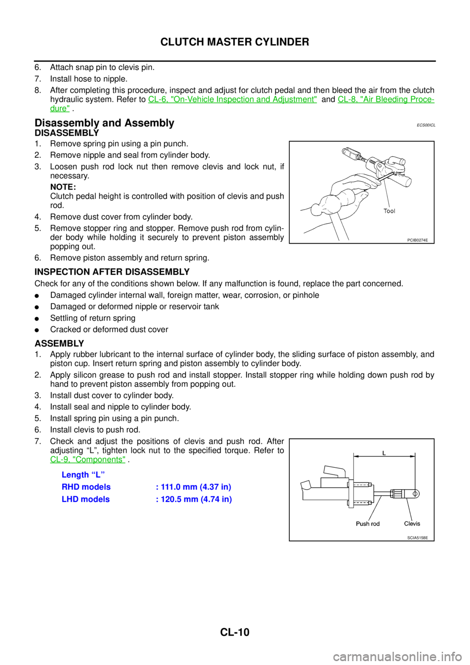
1. Remove spring pin using a pin punch.
2. Remove nipple and seal from cylinder body.
3. Loosen push rod lock nut then remove clevis and lock nut, if
necessary.
NOTE:
Clutch pedal height is controlled with position of clevis and push
rod.
4. Remove dust cover from cylinder body.
5. Remove stopper ring and stopper. Remove push rod from cylin-
der body while holding it securely to prevent piston assembly
popping out.
6. Remove piston assembly and return spring.
INSPECTION AFTER DISASSEMBLY
Check for any of the conditions shown below. If any malfunction is found, replace the part concerned.
lDamaged cylinder internal wall, foreign matter, wear, corrosion, or pinhole
lDamaged or deformed nipple or reservoir tank
lSettling of return spring
lCracked or deformed dust cover
ASSEMBLY
1. Apply rubber lubricant to the internal surface of cylinder body, the sliding surface of piston assembly, and
piston cup. Insert return spring and piston assembly to cylinder body.
2. Apply silicon grease to push rod and install stopper. Install stopper ring while holding down push rod by
hand to prevent piston assembly from popping out.
3. Install dust cover to cylinder body.
4. Install seal and nipple to cylinder body.
5. Install spring pin using a pin punch.
6. Install clevis to push rod.
7. Check and adjust the positions of clevis and push rod. After
adjusting “L”, tighten lock nut to the specified torque. Refer to
CL-9, "
Components".
PCIB0274E
Length “L”
RHD models : 111.0 mm (4.37 in)
LHD models : 120.5 mm (4.74 in)
SCIA5158E
Page 896 of 3171

CO-12
RADIATOR
3. Remove engine cover. Refer toEM-20, "INTAKE MANIFOLD".
4. Remove air inlet hoses between engine to charge air cooler. Refer toEM-18, "
CHARGE AIR COOLER".
5. Disconnect radiator hose (upper and lower) and reservoir tank hose.
CAUTION:
Be careful not to allow engine coolant to contact drive belts.
6. Remove reservoir tank.
7. Remove cooling fans (crankshaft driven type and motor driven type) and radiator shrouds (upper and
lower). Refer toCO-19, "
COOLING FAN".
8. Disconnect A/T fluid cooler hoses. (A/T models)
lInstall blind plug to avoid leakage of A/T fluid.
9. Remove radiator mounting brackets.
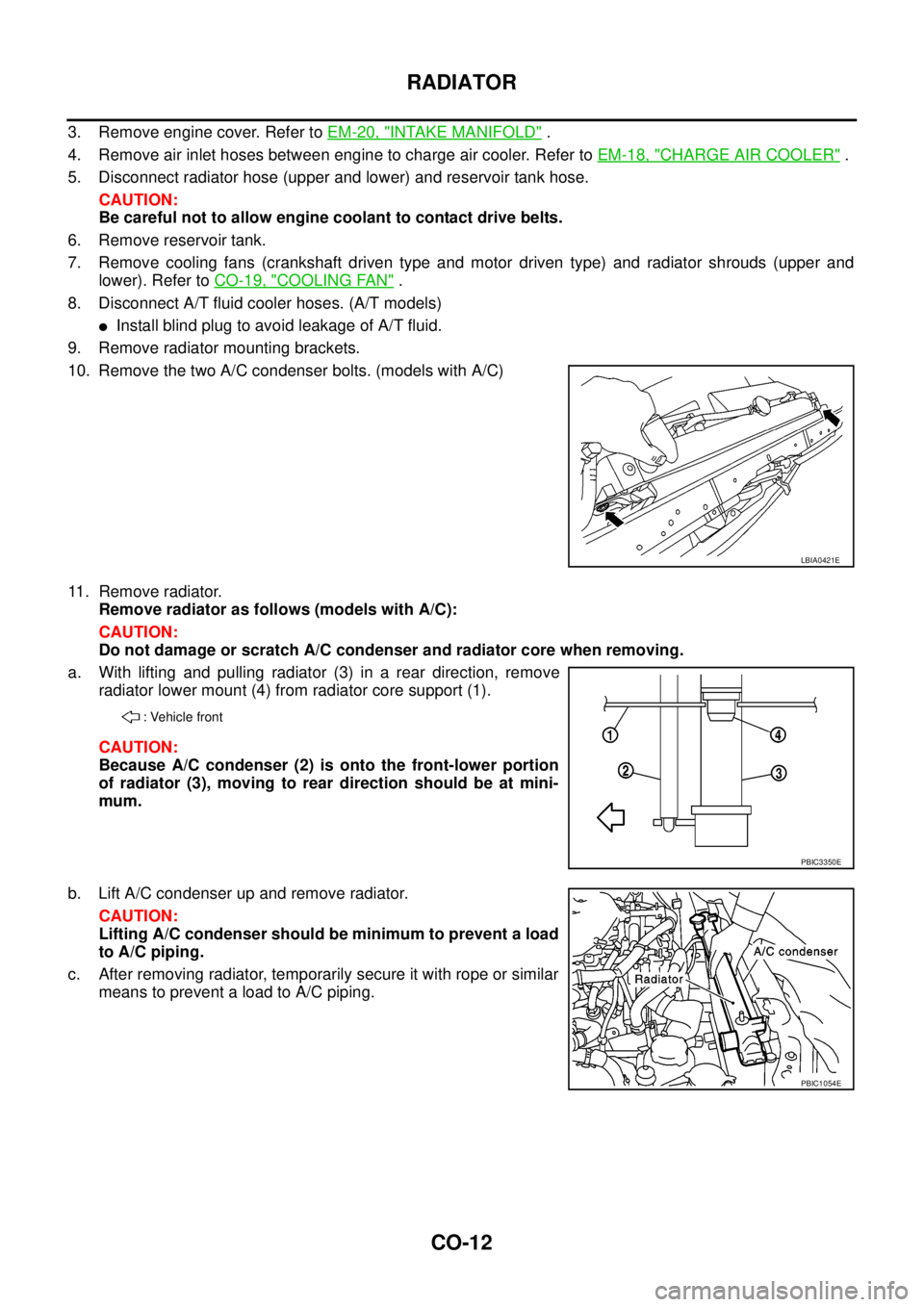
10. Remove the two A/C condenser bolts. (models with A/C)
11. Remove radiator.
Remove radiator as follows (models with A/C):
CAUTION:
Do not damage or scratch A/C condenser and radiator core when removing.
a. With lifting and pulling radiator (3) in a rear direction, remove
radiator lower mount (4) from radiator core support (1).
CAUTION:
Because A/C condenser (2) is onto the front-lower portion
of radiator (3), moving to rear direction should be at mini-
mum.
b. Lift A/C condenser up and remove radiator.
CAUTION:
Lifting A/C condenser should be minimum to prevent a load
to A/C piping.
c. After removing radiator, temporarily secure it with rope or similar
means to prevent a load to A/C piping.
LBIA0421E
: Vehicle front
PBIC3350E
PBIC1054E
Page 902 of 3171
CO-18
RADIATOR (ALUMINUM TYPE)
5. Make sure that there is no leakage.
Refer toCO-18, "
INSPECTION".
INSPECTION
1. Apply pressure with the radiator cap tester adapter [SST] and
the radiator cap tester (commercial service tool).
WARNING:
To prevent the risk of hose coming undone while under
pressure, securely fasten it down with hose clamp.
CAUTION:
Attach hose to A/T fluid cooler to seal its inlet and outlet. (A/
T models)
2. Check for leakage by soaking radiator in water container with
the testing pressure applied.Testing pressure
: 157 kPa (1.57 bar, 1.6 kg/cm
2,23psi)
SLC933
SLC934
Page 905 of 3171

WATER PUMP
CO-21
C
D
E
F
G
H
I
J
K
L
MA
CO
WAT E R P U MPPFP:21020
ComponentsEBS01F6K
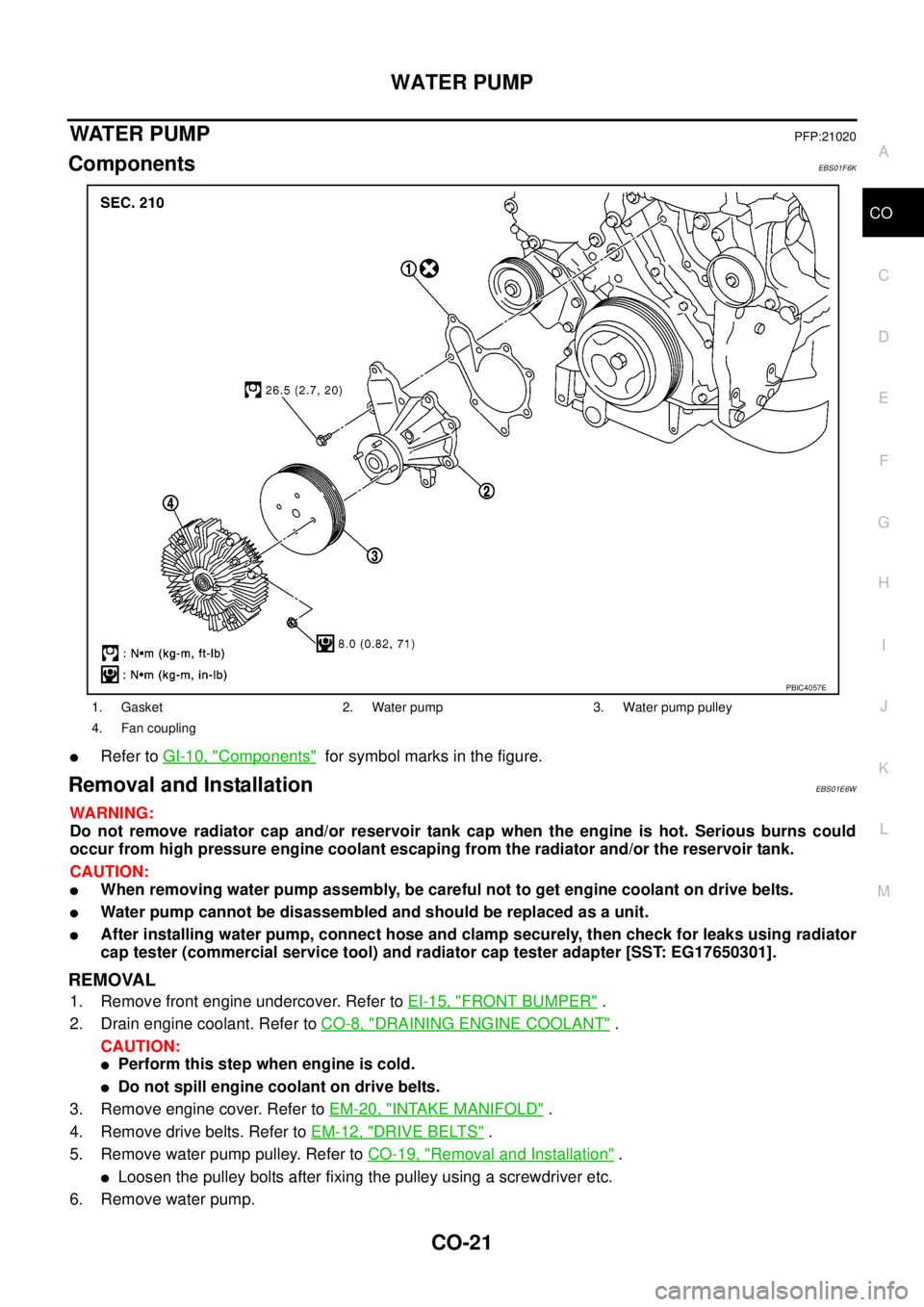
lRefer toGI-10, "Components"for symbol marks in the figure.
Removal and InstallationEBS01E6W
WARNING:
Do not remove radiator cap and/or reservoir tank cap when the engine is hot. Serious burns could
occur from high pressure engine coolant escaping from the radiator and/or the reservoir tank.
CAUTION:
lWhen removing water pump assembly, be careful not to get engine coolant on drive belts.
lWater pump cannot be disassembled and should be replaced as a unit.
lAfter installing water pump, connect hose and clamp securely, then check for leaks using radiator
cap tester (commercial service tool) and radiator cap tester adapter [SST: EG17650301].
REMOVAL
1. Remove front engine undercover. Refer toEI-15, "FRONT BUMPER".
2. Drain engine coolant. Refer toCO-8, "
DRAINING ENGINE COOLANT".
CAUTION:
lPerform this step when engine is cold.
lDo not spill engine coolant on drive belts.
3. Remove engine cover. Refer toEM-20, "
INTAKE MANIFOLD".
4. Remove drive belts. Refer toEM-12, "
DRIVE BELTS".
5. Remove water pump pulley. Refer toCO-19, "
Removal and Installation".
lLoosen the pulley bolts after fixing the pulley using a screwdriver etc.
6. Remove water pump.
1. Gasket 2. Water pump 3. Water pump pulley
4. Fan coupling
PBIC4057E
Page 908 of 3171

CO-24
THERMOSTAT AND WATER PIPING
Removal and Installation
EBS01E6X
WARNING:
Do not remove radiator cap and/or reservoir tank cap when engine is hot. Serious burns could occur
from high pressure engine coolant escaping from radiator and/or reservoir tank.
REMOVAL
1. Remove front engine undercover and middle engine undercover. Refer toEI-15, "FRONT BUMPER".
2. Drain engine coolant from radiator drain plug at the bottom of radiator, and from water drain plug at the
side of cylinder block. Refer toCO-7, "
Changing Engine Coolant"andEM-110, "CYLINDER BLOCK".
CAUTION:
Perform this step when engine is cold.
3. Remove engine cover. Refer toEM-20, "
INTAKE MANIFOLD".
4. Disconnect radiator hoses (upper and lower) from engine side. Refer toCO-11, "
RADIATOR".
5. Remove air inlet pipe and air duct between air cleaner case and turbocharger. Refer toEM-15, "
AIR
CLEANER AND AIR DUCT"andEM-28, "TURBO CHARGER".
6. Remove water outlet, water inlet and thermostat.
7. Remove thermostat housing.
8. Disconnect heater return hose and water hoses at heater return pipe side, and remove heater return pipe.
9. Remove oil level gauge guide mounting bolt, vacuum hoses (to turbocharger boost control solenoid valve)
and spill hose. Refer toEM-36, "
OIL PAN AND OIL STRAINER",EM-20, "INTAKE MANIFOLD"andEM-
44, "INJECTION TUBE AND FUEL INJECTOR".
10. Disconnect water hoses (to EGR cooler) (A/T models), vacuum hoses and heater feed hose at heater
feed pipe side, and remove heater feed pipe. Refer toEM-20, "
INTAKE MANIFOLD".
INSPECTION AFTER REMOVAL
Thermostat
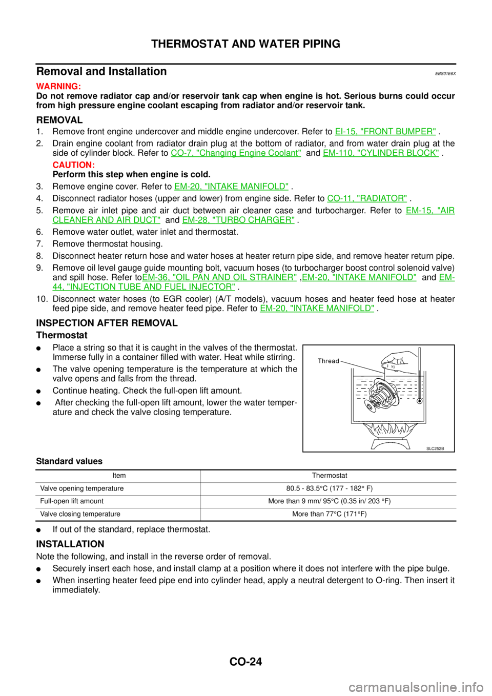
lPlace a string so that it is caught in the valves of the thermostat.
Immerse fully in a container filled with water. Heat while stirring.
lThe valve opening temperature is the temperature at which the
valve opens and falls from the thread.
lContinue heating. Check the full-open lift amount.
lAfter checking the full-open lift amount, lower the water temper-
ature and check the valve closing temperature.
Standard values
lIf out of the standard, replace thermostat.
INSTALLATION
Note the following, and install in the reverse order of removal.
lSecurely insert each hose, and install clamp at a position where it does not interfere with the pipe bulge.
lWhen inserting heater feed pipe end into cylinder head, apply a neutral detergent to O-ring. Then insert it
immediately.
SLC252B
Item Thermostat
Valve opening temperature 80.5 - 83.5°C (177 - 182°F)
Full-open lift amount More than 9 mm/ 95°C (0.35 in/ 203°F)
Valve closing temperature More than 77°C(171°F)