2005 NISSAN NAVARA ECU
[x] Cancel search: ECUPage 909 of 3171
THERMOSTAT AND WATER PIPING
CO-25
C
D
E
F
G
H
I
J
K
L
MA
CO
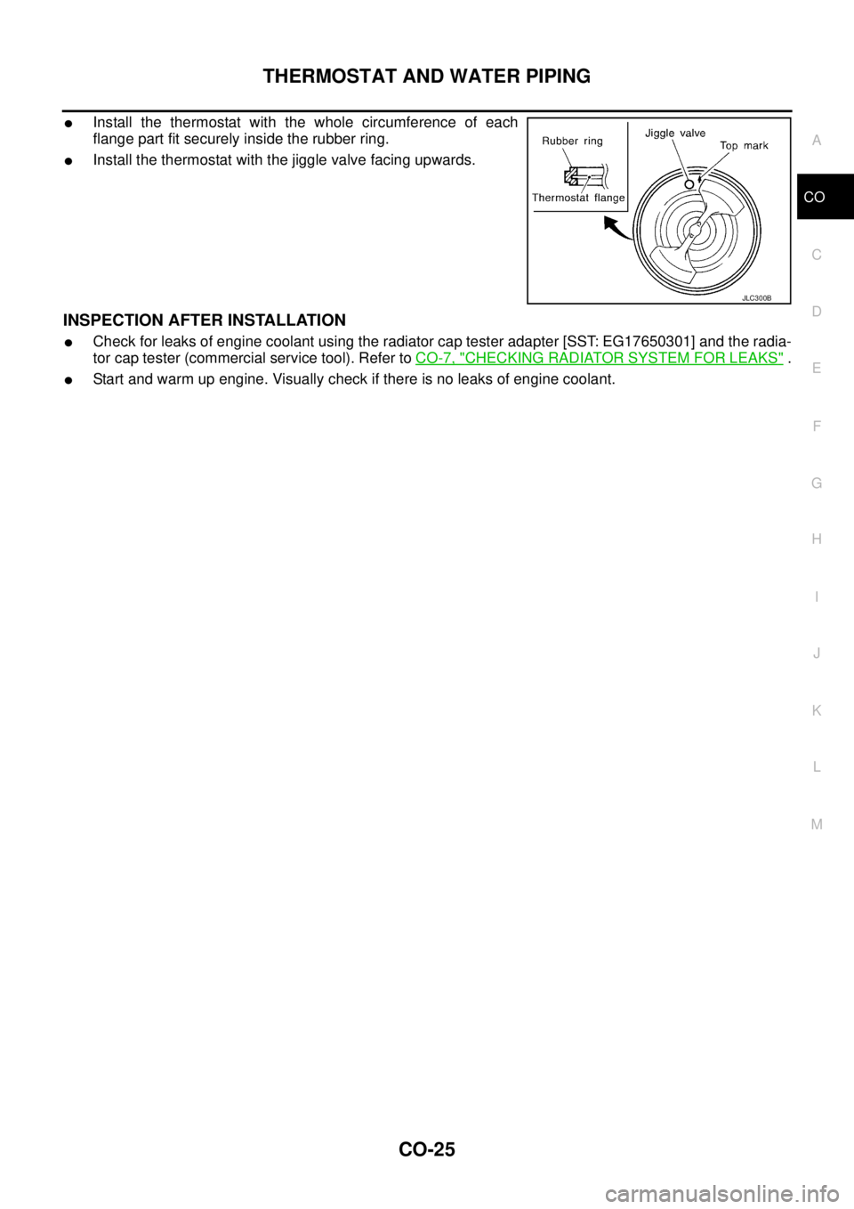
lInstall the thermostat with the whole circumference of each
flange part fit securely inside the rubber ring.
lInstall the thermostat with the jiggle valve facing upwards.
INSPECTION AFTER INSTALLATION
lCheck for leaks of engine coolant using the radiator cap tester adapter [SST: EG17650301] and the radia-
tor cap tester (commercial service tool). Refer toCO-7, "
CHECKING RADIATOR SYSTEM FOR LEAKS".
lStart and warm up engine. Visually check if there is no leaks of engine coolant.
JLC300B
Page 990 of 3171

EC-10
PRECAUTIONS
PRECAUTIONS
PFP:00001
Precautions for Supplemental Restraint System (SRS) “AIR BAG” and “SEAT
BELT PRE-TENSIONER”
EBS01KC5
The Supplemental Restraint System such as “AIR BAG” and “SEAT BELT PRE-TENSIONER”, used along
with a front seat belt, helps to reduce the risk or severity of injury to the driver and front passenger for certain
types of collision. Information necessary to service the system safely is included in the SRS and SB section of
this Service Manual.
WARNING:
lTo avoid rendering the SRS inoperative, which could increase the risk of personal injury or death
in the event of a collision which would result in air bag inflation, all maintenance must be per-
formed by an authorized NISSAN/INFINITI dealer.
lImproper maintenance, including incorrect removal and installation of the SRS, can lead to per-
sonal injury caused by unintentional activation of the system. For removal of Spiral Cable and Air
Bag Module, see the SRS section.
lDo not use electrical test equipment on any circuit related to the SRS unless instructed to in this
Service Manual. SRS wiring harnesses can be identified by yellow and/or orange harnesses or
harness connectors.
On Board Diagnostic (OBD) System of EngineEBS01KC6
The ECM has an on board diagnostic system. It will light up the malfunction indicator (MI) to warn the driver of
a malfunction causing emission deterioration.
CAUTION:
lBe sure to turn the ignition switch OFF and disconnect the battery negative cable before any
repair or inspection work. The open/short circuit of related switches, sensors, solenoid valves,
etc. will cause the MI to light up.
lBe sure to connect and lock the connectors securely after work. A loose (unlocked) connector will
cause the MI to light up due to the open circuit. (Be sure the connector is free from water, grease,
dirt, bent terminals, etc.)
lCertain systems and components, especially those related to OBD, may use a new style slide-
locking type harness connector. For description and how to disconnect, refer toPG-75, "
HAR-
NESS CONNECTOR".
lBe sure to route and secure the harnesses properly after work. The interference of the harness
with a bracket, etc. may cause the MI to light up due to the short circuit.
lBe sure to connect rubber tubes properly after work. A misconnected or disconnected rubber tube
may cause the MI to light up due to the malfunction of the fuel system, etc.
lBe sure to erase the unnecessary malfunction information (repairs completed) from the ECM
before returning the vehicle to the customer.
PrecautionsEBS01KC7
lAlways use a 12 volt battery as power source.
lDo not attempt to disconnect battery cables while engine is
running.
lBefore connecting or disconnecting the ECM harness con-
nector, turn ignition switch OFF and disconnect battery
negative cable. Failure to do so may damage the ECM
because battery voltage is applied to ECM even if ignition
switch is turned off.
lBefore removing parts, turn ignition switch OFF and then
disconnect battery negative cable.
SEF289H
Page 991 of 3171
PRECAUTIONS
EC-11
C
D
E
F
G
H
I
J
K
L
MA
EC
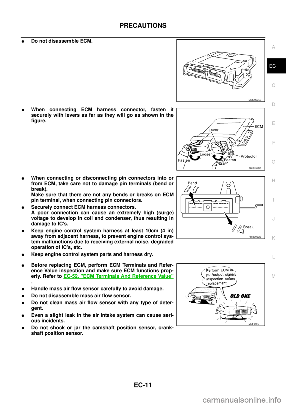
lDo not disassemble ECM.
lWhen connecting ECM harness connector, fasten it
securely with levers as far as they will go as shown in the
figure.
lWhen connecting or disconnecting pin connectors into or
from ECM, take care not to damage pin terminals (bend or
break).
Make sure that there are not any bends or breaks on ECM
pin terminal, when connecting pin connectors.
lSecurely connect ECM harness connectors.
A poor connection can cause an extremely high (surge)
voltage to develop in coil and condenser, thus resulting in
damage to IC's.
lKeep engine control system harness at least 10cm (4 in)
away from adjacent harness, to prevent engine control sys-
tem malfunctions due to receiving external noise, degraded
operation of IC's, etc.
lKeep engine control system parts and harness dry.
lBefore replacing ECM, perform ECM Terminals and Refer-
ence Value inspection and make sure ECM functions prop-
erly. Refer toEC-52, "
ECM Terminals And Reference Value"
.
lHandle mass air flow sensor carefully to avoid damage.
lDo not disassemble mass air flow sensor.
lDo not clean mass air flow sensor with any type of deter-
gent.
lEven a slight leak in the air intake system can cause seri-
ous incidents.
lDo not shock or jar the camshaft position sensor, crank-
shaft position sensor.
MBIB0625E
PBIB1512E
PBIB0090E
MEF040D
Page 1008 of 3171
EC-28
ON BOARD DIAGNOSTIC (OBD) SYSTEM
lIf the battery is disconnected, the emission-related diagnostic information will be lost within 24
hours.
lThe following data are cleared when the ECM memory is erased.
–Diagnostic trouble codes
–Freeze frame data
–Fuel pump learning value
Actual work procedures are explained using a DTC as an example. Be careful so that not only the DTC, but all
of the data listed above, are cleared from the ECM memory during work procedures.
Freeze Frame DataEBS01KCP
The ECM records the driving conditions such as calculated load value, engine coolant temperature, engine
speed, vehicle speed and intake manifold pressure at the moment a malfunction is detected.
The data, stored together with the DTC data, are called freeze frame data and displayed on CONSULT-II. For
details, seeEC-28, "
Freeze Frame Data".
Only one set of freeze frame data can be stored in the ECM. If freeze frame data is stored in the ECM memory
and another freeze frame data occurs later, the first (original) freeze frame data remains unchanged in the
ECM memory.
Freeze frame data (along with the DTCs) are cleared when the ECM memory is erased. Procedures for clear-
ing the ECM memory are described inEC-27, "
HOW TO ERASE DTC".
NATS (Nissan Anti-theft System)EBS01KCQ
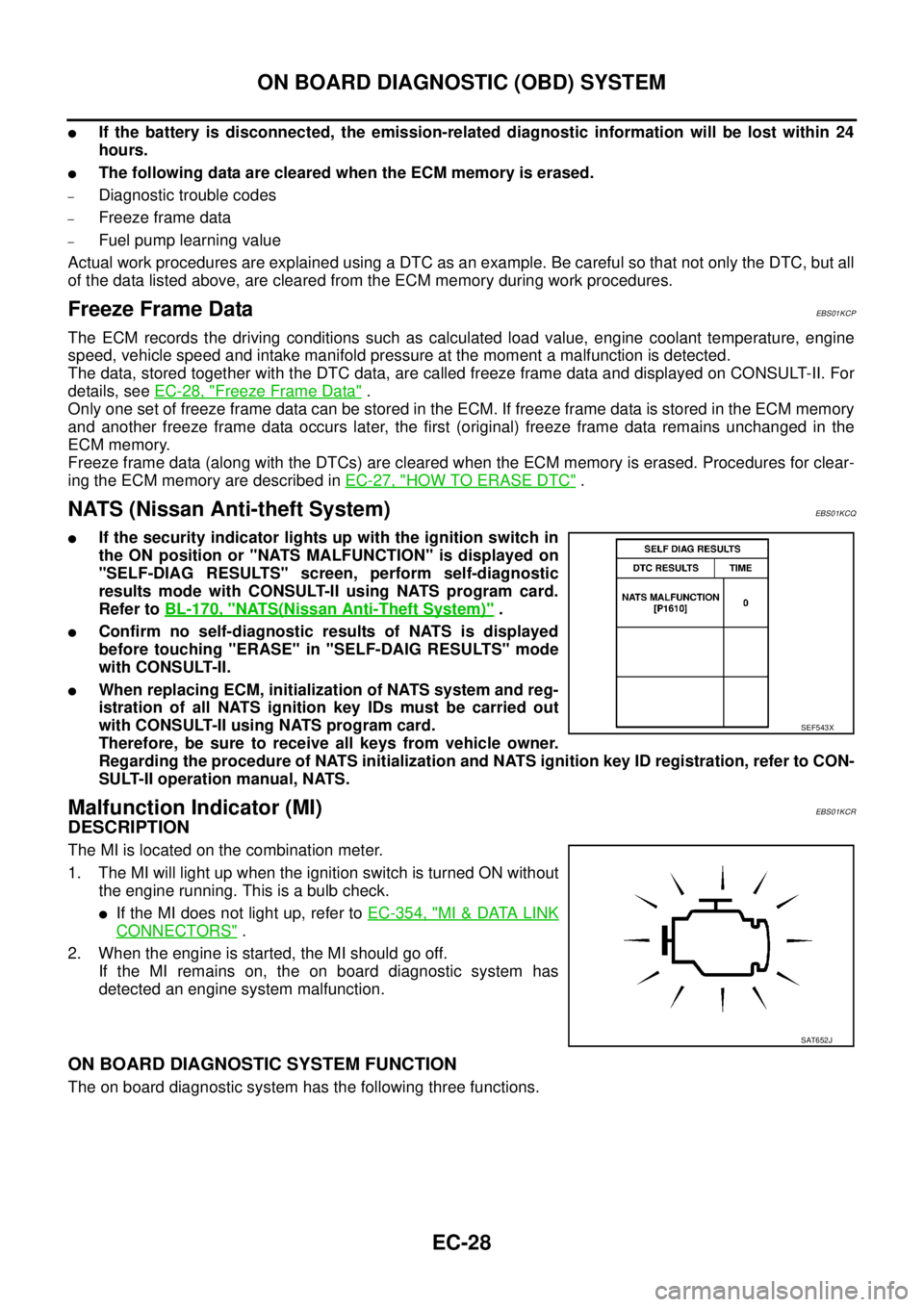
lIf the security indicator lights up with the ignition switch in
the ON position or "NATS MALFUNCTION" is displayed on
"SELF-DIAG RESULTS" screen, perform self-diagnostic
results mode with CONSULT-II using NATS program card.
Refer toBL-170, "
NATS(Nissan Anti-Theft System)".
lConfirm no self-diagnostic results of NATS is displayed
before touching "ERASE" in "SELF-DAIG RESULTS" mode
with CONSULT-II.
lWhen replacing ECM, initialization of NATS system and reg-
istration of all NATS ignition key IDs must be carried out
with CONSULT-II using NATS program card.
Therefore, be sure to receive all keys from vehicle owner.
Regarding the procedure of NATS initialization and NATS ignition key ID registration, refer to CON-
SULT-II operation manual, NATS.
Malfunction Indicator (MI)EBS01KCR
DESCRIPTION
The MI is located on the combination meter.
1. The MI will light up when the ignition switch is turned ON without
the engine running. This is a bulb check.
lIf the MI does not light up, refer toEC-354, "MI&DATA LINK
CONNECTORS".
2. When the engine is started, the MI should go off.
If the MI remains on, the on board diagnostic system has
detected an engine system malfunction.
ON BOARD DIAGNOSTIC SYSTEM FUNCTION
The on board diagnostic system has the following three functions.
SEF543X
SAT652J
Page 1050 of 3171
EC-70
TROUBLE DIAGNOSIS FOR INTERMITTENT INCIDENT
TROUBLE DIAGNOSIS FOR INTERMITTENT INCIDENT
PFP:00006
DescriptionEBS01KD4
Intermittent incidents may occur. In many cases, the incident resolves itself (the part or circuit function returns
to normal without intervention). It is important to realize that the symptoms described in the customer's com-
plaint often do not recur on DTC visits. Realize also that the most frequent cause of intermittent incidents
occurrences is poor electrical connections. Because of this, the conditions under which the incident occurred
may not be clear. Therefore, circuit checks made as part of the standard diagnostic procedure may not indi-
cate the specific malfunctioning area.
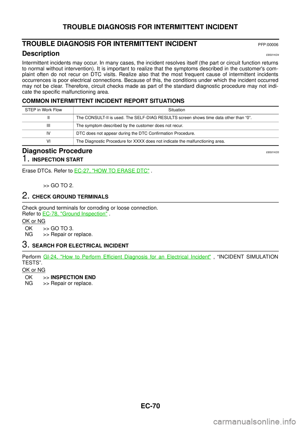
COMMON INTERMITTENT INCIDENT REPORT SITUATIONS
Diagnostic ProcedureEBS01KD5
1.INSPECTION START
Erase DTCs. Refer toEC-27, "
HOW TO ERASE DTC".
>> GO TO 2.
2.CHECK GROUND TERMINALS
Check ground terminals for corroding or loose connection.
Refer toEC-78, "
Ground Inspection".
OK or NG
OK >> GO TO 3.
NG >> Repair or replace.
3.SEARCH FOR ELECTRICAL INCIDENT
PerformGI-24, "
How to Perform Efficient Diagnosis for an Electrical Incident", “INCIDENT SIMULATION
TESTS”.
OK or NG
OK >>INSPECTION END
NG >> Repair or replace.
STEP in Work Flow Situation
II The CONSULT-II is used. The SELF-DIAG RESULTS screen shows time data other than “0”.
III The symptom described by the customer does not recur.
IV DTC does not appear during the DTC Confirmation Procedure.
VI The Diagnostic Procedure for XXXX does not indicate the malfunctioning area.
Page 1058 of 3171
EC-78
POWER SUPPLY AND GROUND CIRCUIT
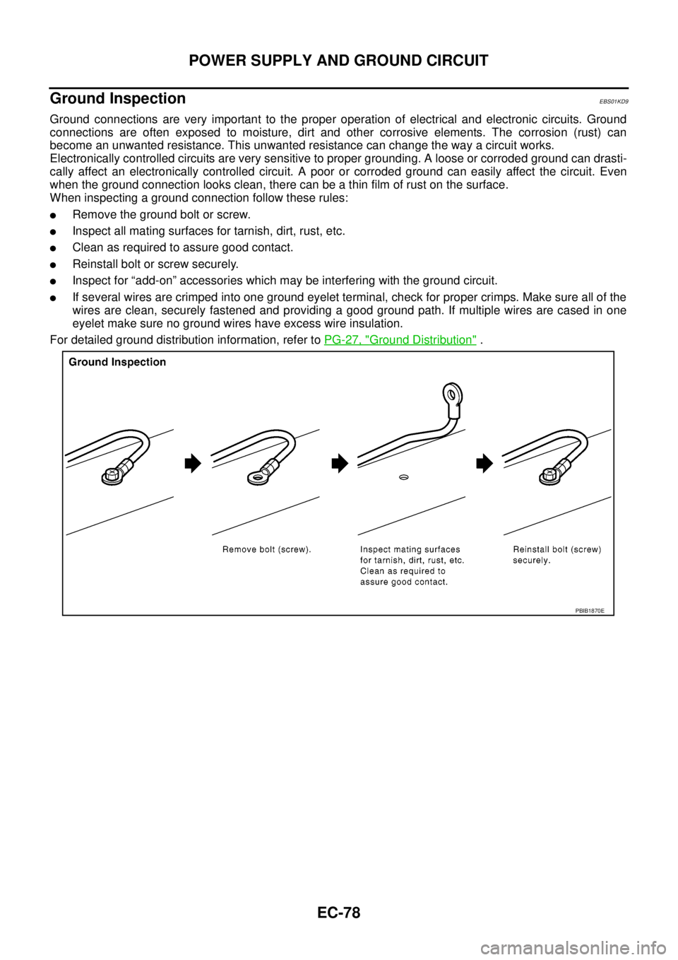
Ground Inspection
EBS01KD9
Ground connections are very important to the proper operation of electrical and electronic circuits. Ground
connections are often exposed to moisture, dirt and other corrosive elements. The corrosion (rust) can
become an unwanted resistance. This unwanted resistance can change the way a circuit works.
Electronically controlled circuits are very sensitive to proper grounding. A loose or corroded ground can drasti-
cally affect an electronically controlled circuit. A poor or corroded ground can easily affect the circuit. Even
when the ground connection looks clean, there can be a thin film of rust on the surface.
When inspecting a ground connection follow these rules:
lRemove the ground bolt or screw.
lInspect all mating surfaces for tarnish, dirt, rust, etc.
lClean as required to assure good contact.
lReinstall bolt or screw securely.
lInspect for “add-on” accessories which may be interfering with the ground circuit.
lIf several wires are crimped into one ground eyelet terminal, check for proper crimps. Make sure all of the
wires are clean, securely fastened and providing a good ground path. If multiple wires are cased in one
eyelet make sure no ground wires have excess wire insulation.
For detailed ground distribution information, refer toPG-27, "
Ground Distribution".
PBIB1870E
Page 1170 of 3171
EC-190
DTC P0504 ASCD BRAKE SWITCH
On Board Diagnosis Logic
EBS01KHW
The MI will not light up for this diagnosis.
DTC confirmation ProcedureEBS01KHX
CAUTION:
Always drive vehicle at a safe speed.
NOTE:
If DTC Confirmation Procedure has been previously conducted, always turn ignition switch OFF and wait at
least 10 seconds before conducting the next test.
TESTING CONDITION:
Steps 3 and 4 may be conducted with the drive wheels lifted in the shop or by driving the vehicle. If a
road test is expected to be easier, it is unnecessary to lift the vehicle.
WITH CONSULT-II
1. Start engine.
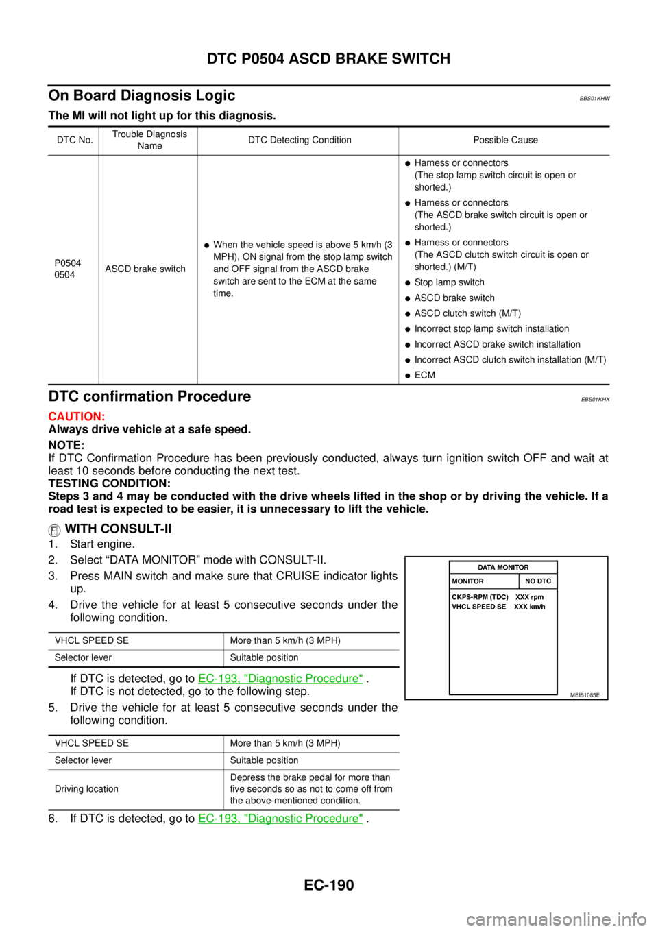
2. Select “DATA MONITOR” mode with CONSULT-II.
3. Press MAIN switch and make sure that CRUISE indicator lights
up.
4. Drive the vehicle for at least 5 consecutive seconds under the
following condition.
If DTC is detected, go toEC-193, "
Diagnostic Procedure".
If DTC is not detected, go to the following step.
5. Drive the vehicle for at least 5 consecutive seconds under the
following condition.
6. If DTC is detected, go toEC-193, "
Diagnostic Procedure".
DTC No.Trouble Diagnosis
NameDTC Detecting Condition Possible Cause
P0504
0504ASCD brake switch
lWhen the vehicle speed is above 5 km/h (3
MPH), ON signal from the stop lamp switch
and OFF signal from the ASCD brake
switch are sent to the ECM at the same
time.
lHarness or connectors
(The stop lamp switch circuit is open or
shorted.)
lHarness or connectors
(The ASCD brake switch circuit is open or
shorted.)
lHarness or connectors
(The ASCD clutch switch circuit is open or
shorted.) (M/T)
lStop lamp switch
lASCD brake switch
lASCD clutch switch (M/T)
lIncorrectstoplampswitchinstallation
lIncorrect ASCD brake switch installation
lIncorrect ASCD clutch switch installation (M/T)
lECM
VHCL SPEED SE More than 5 km/h (3 MPH)
Selector lever Suitable position
VHCL SPEED SE More than 5 km/h (3 MPH)
Selector lever Suitable position
Driving locationDepress the brake pedal for more than
five seconds so as not to come off from
the above-mentioned condition.
MBIB1085E
Page 1171 of 3171

DTC P0504 ASCD BRAKE SWITCH
EC-191
C
D
E
F
G
H
I
J
K
L
MA
EC
WITHOUT CONSULT-II
1. Start engine.
2. Press MAIN switch and make sure that CRUISE indicator lights up.
3. Drive the vehicle for at least 5 consecutive seconds under the following condition.
4. Turn ignition switch OFF, wait at least 10 seconds and then turn ON.
5. Perform Diagnostic Test Mode II (Self-diagnostic results) with ECM.
If DTC is detected, go toEC-193, "
Diagnostic Procedure".
If DTC is not detected, go to the following step.
6. Start engine.
7. Drive the vehicle for at least 5 consecutive seconds under the following condition.
8. If DTC is detected, go toEC-193, "
Diagnostic Procedure".
Vehiclespeed Morethan5km/h(3MPH)
Selector lever Suitable position
Vehiclespeed Morethan5km/h(3MPH)
Selector lever Suitable position
Driving locationDepress the brake pedal for more than
five seconds so as not to come off from
the above-mentioned condition.