2005 NISSAN NAVARA ECU
[x] Cancel search: ECUPage 580 of 3171

BCS-14
BCM (BODY CONTROL MODULE)
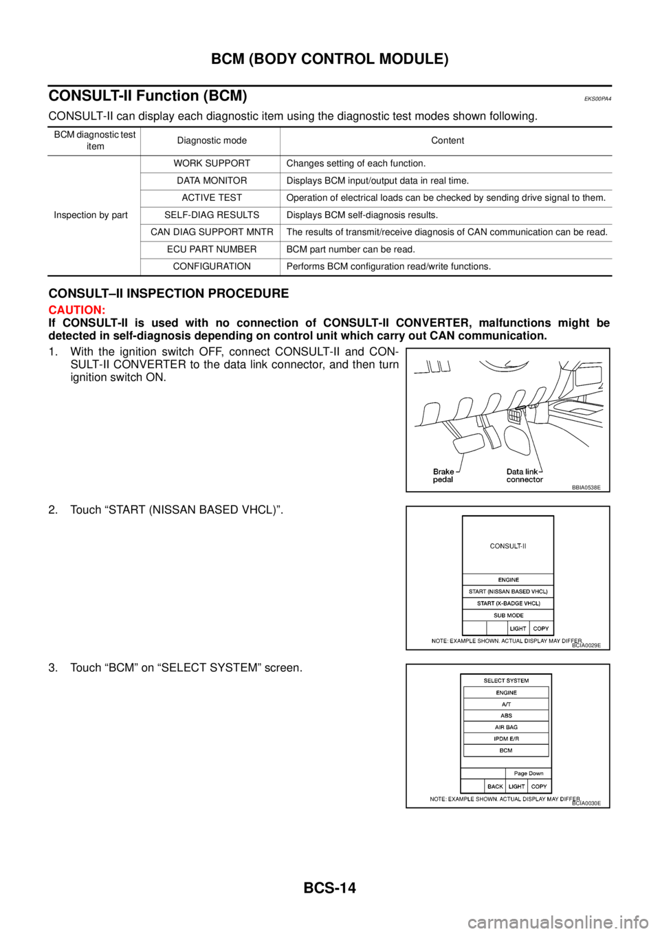
CONSULT-II Function (BCM)
EKS00PA4
CONSULT-II can display each diagnostic item using the diagnostic test modes shown following.
CONSULT–II INSPECTION PROCEDURE
CAUTION:
If CONSULT-II is used with no connection of CONSULT-II CONVERTER, malfunctions might be
detected in self-diagnosis depending on control unit which carry out CAN communication.
1. With the ignition switch OFF, connect CONSULT-II and CON-
SULT-II CONVERTER to the data link connector, and then turn
ignition switch ON.
2. Touch “START (NISSAN BASED VHCL)”.
3. Touch “BCM” on “SELECT SYSTEM” screen.
BCM diagnostic test
itemDiagnostic mode Content
Inspection by partWORK SUPPORT Changes setting of each function.
DATA MONITOR Displays BCM input/output data in real time.
ACTIVE TEST Operation of electrical loads can be checked by sending drive signal to them.
SELF-DIAG RESULTS Displays BCM self-diagnosis results.
CAN DIAG SUPPORT MNTR The results of transmit/receive diagnosis of CAN communication can be read.
ECU PART NUMBER BCM part number can be read.
CONFIGURATION Performs BCM configuration read/write functions.
BBIA0538E
BCIA0029E
BCIA0030E
Page 581 of 3171

BCM (BODY CONTROL MODULE)
BCS-15
C
D
E
F
G
H
I
J
L
MA
B
BCS
4. Select item to be diagnosed on “SELECT TEST ITEM” screen.
ITEMS OF EACH PART
NOTE:
CONSULT-II will only display systems the vehicle possesses.
WORK SUPPORT
Operation Procedure
1. Touch “BCM” on “SELECT TEST ITEM” screen.
PKIC0325E
System and itemCONSULT-II
displayDiagnostic test mode (Inspection by part)
WORK
SUPPORTSELF-
DIAG
RESULTSCAN DIAG
SUPPORT
MNTRDATA
MONITORECU
PA RT
NUMBERACTIVE
TESTCON-
FIGU-
RATION
BCM BCM´´ ´ ´ ´
Power door lock sys-
temDOOR LOCK´´´
Rear window defoggerREAR DEFOG-
GER´´
Warning chime BUZZER´´
Room lamp timer INT LAMP´´´
Headlamp HEAD LAMP´´´
Wiper WIPER´´´
Turn signal lamp
Hazard lampFLASHER´´
Blower fan switch sig-
nal
Air conditioner switch
signalAIR CONDI-
TONER´
Combination switch COMB SW´
NATS IMMU´´
Interior lamp battery
saverBATTERY
SAVER´´´
Theft alarm THEFT ALARM´´´
Retained power control RETAINED PWR´´´
Oil pressure switch SIGNAL BUFFER´´
PKIC0325E
Page 585 of 3171

BL-1
BODY, LOCK & SECURITY SYSTEM
IBODY
CONTENTS
C
D
E
F
G
H
J
K
L
M
SECTIONBL
A
B
BL
BODY, LOCK & SECURITY SYSTEM
PRECAUTIONS .......................................................... 4
Precautions for Supplemental Restraint System
(SRS)“AIRBAG”and“SEATBELTPRE-TEN-
SIONER” .................................................................. 4
Precautions for procedures with out cowl top cover..... 4
Precautions for Work ................................................ 4
Wiring Diagrams and Trouble Diagnosis .................. 4
PREPARATION ........................................................... 5
Commercial Service Tools ........................................ 5
SQUEAK AND RATTLE TROUBLE DIAGNOSES..... 6
Work Flow ................................................................ 6
CUSTOMER INTERVIEW ..................................... 6
DUPLICATE THE NOISE AND TEST DRIVE ....... 7
CHECK RELATED SERVICE BULLETINS ........... 7
LOCATE THE NOISE AND IDENTIFY THE
ROOT CAUSE ...................................................... 7
REPAIR THE CAUSE ........................................... 7
CONFIRM THE REPAIR ....................................... 8
Generic Squeak and Rattle Troubleshooting ........... 8
INSTRUMENT PANEL .......................................... 8
CENTER CONSOLE ............................................. 8
DOORS ................................................................. 8
TRUNK .................................................................. 9
SUNROOF/HEADLINING ..................................... 9
SEATS ................................................................... 9
UNDERHOOD ....................................................... 9
Diagnostic Worksheet ............................................ 10
HOOD ....................................................................... 12
Fitting Adjustment .................................................. 12
LONGITUDINAL AND LATERAL CLEARANCE
ADJUSTMENT .................................................... 13
FRONT END HEIGHT ADJUSTMENT ............... 13
SURFACE HEIGHT ADJUSTMENT ................... 13
Removal and Installation of Hood Assembly .......... 14
REMOVAL ........................................................... 14
INSTALLATION ................................................... 14
Removal and Installation of Hood Hinge ................ 15
REMOVAL ........................................................... 15
INSTALLATION ................................................... 15
Removal and Installation of Hood Lock Control ..... 15REMOVAL ........................................................... 15
INSTALLATION ................................................... 16
Hood Lock Control Inspection ................................ 17
RADIATOR CORE SUPPORT .................................. 18
Removal and Installation ........................................ 18
REMOVAL ........................................................... 18
INSTALLATION ................................................... 19
FRONT FENDER ...................................................... 20
Removal and Installation ........................................ 20
REMOVAL ........................................................... 20
INSTALLATION ................................................... 20
POWER DOOR LOCK SYSTEM .............................. 21
Component Parts and Harness Connector Location... 21
KING CAB ........................................................... 21
DOUBLE CAB ..................................................... 22
System Description ................................................. 23
OUTLINE ............................................................. 24
CAN Communication System Description .............. 25
CAN Communication Unit ....................................... 25
Schematic ............................................................... 26
Wiring Diagram —D/LOCK— ................................. 27
Terminals and Reference Value for BCM ............... 34
CONSULT-II Function (BCM) ................................. 35
CONSULT-II BASIC OPERATION PROCEDURE
... 35
CONSULT-II APPLICATION ITEMS .................... 36
Work Flow ............................................................... 37
Trouble Diagnoses Chart by Symptom ................... 37
Check Power Supply and Ground Circuit ............... 37
Check Door Switch ................................................. 39
CHECK DOOR SWITCH (DOUBLE CAB) .......... 39
CHECK DOOR SWITCH (KING CAB) ................ 41
Check Key Switch ................................................... 43
Check Door Key Cylinder Switch (LHD Model Only)... 45
Check Front Door Lock Actuator (Driver Side) ....... 48
Check Front Door Lock Actuator (Passenger Side)... 49
Check Front Door Lock Actuator Switch ................. 50
Check Rear Door Lock Actuator LH (Double Cab
Model) ..................................................................... 50
Check Rear Door Lock Actuator RH (Double Cab
Page 591 of 3171

SQUEAK AND RATTLE TROUBLE DIAGNOSES
BL-7
C
D
E
F
G
H
J
K
L
MA
B
BL
DUPLICATE THE NOISE AND TEST DRIVE
If possible, drive the vehicle with the customer until the noise is duplicated. Note any additional information on
the Diagnostic Worksheet regarding the conditions or location of the noise. This information can be used to
duplicate the same conditions when you confirm the repair.
If the noise can be duplicated easily during the test drive, to help identify the source of the noise, try to dupli-
cate the noise with the vehicle stopped by doing one or all of the following:
1) Close a door.
2) Tap or push/pull around the area where the noise appears to be coming from.
3) Rev the engine.
4) Use a floor jack to recreate vehicle “twist”.
5) At idle, apply engine load (electrical load, half-clutch on M/T models, drive position on A/T models).
6) Raisethevehicleonahoistandhitatirewitharubberhammer.
lDrive the vehicle and attempt to duplicate the conditions the customer states exist when the noise occurs.
lIf it is difficult to duplicate the noise, drive the vehicle slowly on an undulating or rough road to stress the
vehicle body.
CHECK RELATED SERVICE BULLETINS
After verifying the customer concern or symptom, check ASIST for Technical Service Bulletins (TSBs) related
to that concern or symptom.
If a TSB relates to the symptom, follow the procedure to repair the noise.
LOCATE THE NOISE AND IDENTIFY THE ROOT CAUSE
1. Narrow down the noise to a general area. To help pinpoint the source of the noise, use a listening tool
(Engine Ear or mechanics stethoscope).
2. Narrow down the noise to a more specific area and identify the cause of the noise by:
lremoving the components in the area that you suspect the noise is coming from.
Do not use too much force when removing clips and fasteners, otherwise clips and fastener can be broken
or lost during the repair, resulting in the creation of new noise.
ltapping or pushing/pulling the component that you suspect is causing the noise.
Do not tap or push/pull the component with excessive force, otherwise the noise will be eliminated only
temporarily.
lfeeling for a vibration with your hand by touching the component(s) that you suspect is (are) causing the
noise.
lplacing a piece of paper between components that you suspect are causing the noise.
llooking for loose components and contact marks.
Refer toBL-8, "
Generic Squeak and Rattle Troubleshooting".
REPAIR THE CAUSE
lIf the cause is a loose component, tighten the component securely.
lIf the cause is insufficient clearance between components:
–separate components by repositioning or loosening and retightening the component, if possible.
–insulate components with a suitable insulator such as urethane pads, foam blocks, felt cloth tape or ure-
thane tape are available through your authorized Nissan Parts Department.
CAUTION:
Do not use excessive force as many components are constructed of plastic and may be damaged.
NOTE:
Always check with the Parts Department for the latest parts information.
Each item can be ordered separately as needed.
URETHANE PADS [1.5 mm (0.059 in) thick]
Insulates connectors, harness, etc.
76268-9E005: 100´135 mm (3.94´5.31 in)/76884-71L01: 60´85 mm (2.36´3.35 in)/76884-71L02: 15´
25 mm (0.59´0.98 in)
INSULATOR (Foam blocks)
Insulates components from contact. Can be used to fill space behind a panel.
73982-9E000: 45 mm (1.77 in) thick, 50´50 mm (1.97´1.97 in)/73982-50Y00: 10 mm (0.39 in) thick, 50
´50 mm (1.97´1.97 in)
INSULATOR (Light foam block)
80845-71L00: 30 mm (1.18 in) thick, 30´50 mm (1.18´1.97 in)
Page 593 of 3171

SQUEAK AND RATTLE TROUBLE DIAGNOSES
BL-9
C
D
E
F
G
H
J
K
L
MA
B
BL
TRUNK
Trunk noises are often caused by a loose jack or loose items put into the trunk by the owner.
In addition look for:
1. Trunk lid dumpers out of adjustment
2. Trunk lid striker out of adjustment
3. Trunk lid torsion bars knocking together
4. A loose license plate or bracket
Most of these incidents can be repaired by adjusting, securing or insulating the item(s) or component(s) caus-
ing the noise.
SUNROOF/HEADLINING
Noises in the sunroof/headlining area can often be traced to one of the following:
1. Sunroof lid, rail, linkage or seals making a rattle or light knocking noise
2. Sunvisor shaft shaking in the holder
3. Front or rear windshield touching headlining and squeaking
Again, pressing on the components to stop the noise while duplicating the conditions can isolate most of these
incidents. Repairs usually consist of insulating with felt cloth tape.
SEATS
When isolating seat noise it's important to note the position the seat is in and the load placed on the seat when
the noise is present. These conditions should be duplicated when verifying and isolating the cause of the
noise.
Cause of seat noise include:
1. Headrest rods and holder
2. A squeak between the seat pad cushion and frame
3. Rear seatback lock and bracket
These noises can be isolated by moving or pressing on the suspected components while duplicating the con-
ditions under which the noise occurs. Most of these incidents can be repaired by repositioning the component
or applying urethane tape to the contact area.
UNDERHOOD
Some interior noise may be caused by components under the hood or on the engine wall. The noise is then
transmitted into the passenger compartment.
Causes of transmitted underhood noise include:
1. Any component mounted to the engine wall
2. Components that pass through the engine wall
3. Engine wall mounts and connectors
4. Loose radiator mounting pins
5. Hood bumpers out of adjustment
6. Hood striker out of adjustment
These noises can be difficult to isolate since they cannot be reached from the interior of the vehicle. The best
method is to secure, move or insulate one component at a time and test drive the vehicle. Also, engine RPM
or load can be changed to isolate the noise. Repairs can usually be made by moving, adjusting, securing, or
insulating the component causing the noise.
Page 597 of 3171

HOOD
BL-13
C
D
E
F
G
H
J
K
L
MA
B
BL
LONGITUDINAL AND LATERAL CLEARANCE ADJUSTMENT
1. Remove the hood lock, loosen the hood hinge nuts and close the hood.
2. Adjust the lateral and longitudinal clearance, and open the hood to tighten the mounting bolts to the spec-
ified torque.
3. Install the hood lock temporarily, and align the hood striker and lock so that the centers of striker and lock
become vertical viewed from the front, by moving the hood lock laterally.
4. Tighten hood lock mounting bolts to the specified torque.
FRONT END HEIGHT ADJUSTMENT
1. Remove the hood lock and adjust the height by rotating the bumper rubber until the hood becomes 1 to1.5
mm (0.04 to 0.059 in) lower than the fender.
2. Temporarily tighten the hood lock, and position it by engaging it with the hood striker. Check the lock and
striker for looseness, and tighten the hood lock mounting bolts to the specified torque.
CAUTION:
Adjust right/left clearance between hood and each part to the following specification.
SURFACE HEIGHT ADJUSTMENT
1. Remove the hood lock, and adjust the surface height difference of hood, fender and headlamp according
to the fitting standard dimension, by rotating RH and LH bumper rubbers.
2. Install hood lock temporarily, and move hood lock laterally until the centers of striker and lock become ver-
tical when viewed from the front.
3. Check that the hood lock secondary latch is properly engaged with the secondary striker with hood's own
weight.
4. Check that the hood lock primary latch is securely engaged with the hood striker with hood's own weight
by dropping hood from approx. 200 mm (7.87) height.
CAUTION:
Do not drop hood from a height of 300 mm (11.81 in) or more.
5. Move hood lockup and down until striker smoothly engages the lock when the hood is closed.
6. When pulling the hood opener lever gently, make sure that front end of the hood rises by approximately 20
mm (0.79) and that hood striker and hood lock primary latch is disengaged. Also make sure that hood
opener returns to the original position.
7. After adjustment, tighten lock bolts to the specified torque.
CAUTION:
lAfter installing, apply touch-up paint (the body color) onto the head of the hinge mounting nuts.
lAdjust evenness between hood and each part to the following specification.
Portion Clearance
Hood - Front grille A - A (a) 3.7 - 8.3 mm (0.146 - 0.327 in)
Hood - Front fender B - B (c) 3.6 - 5.6 mm (0.142 - 0.220 in)
Hood - Headlamp C - C (e) 6.0 - 8.0 mm (0.236 - 0.315 in)
Portion R / L difference
Hood - Front grille A - A (a) Less than 2.2 mm (0.087 in)
Hood - Front fender B - B (c) Less than 1.0 mm (0.039 In)
Portion Surface height
Hood - Front grille A - A (b) -1.7 - 3.1 mm (-0.067 - 0.122 in)
Hood - Front fender B - B (d) -1.0 - 1.0 mm (-0.039 - 0.039 in)
Hood - Headlamp C - C (f) -1.3 - 2.7 mm (-0.051 - 0.106 in)
Page 600 of 3171

BL-16
HOOD
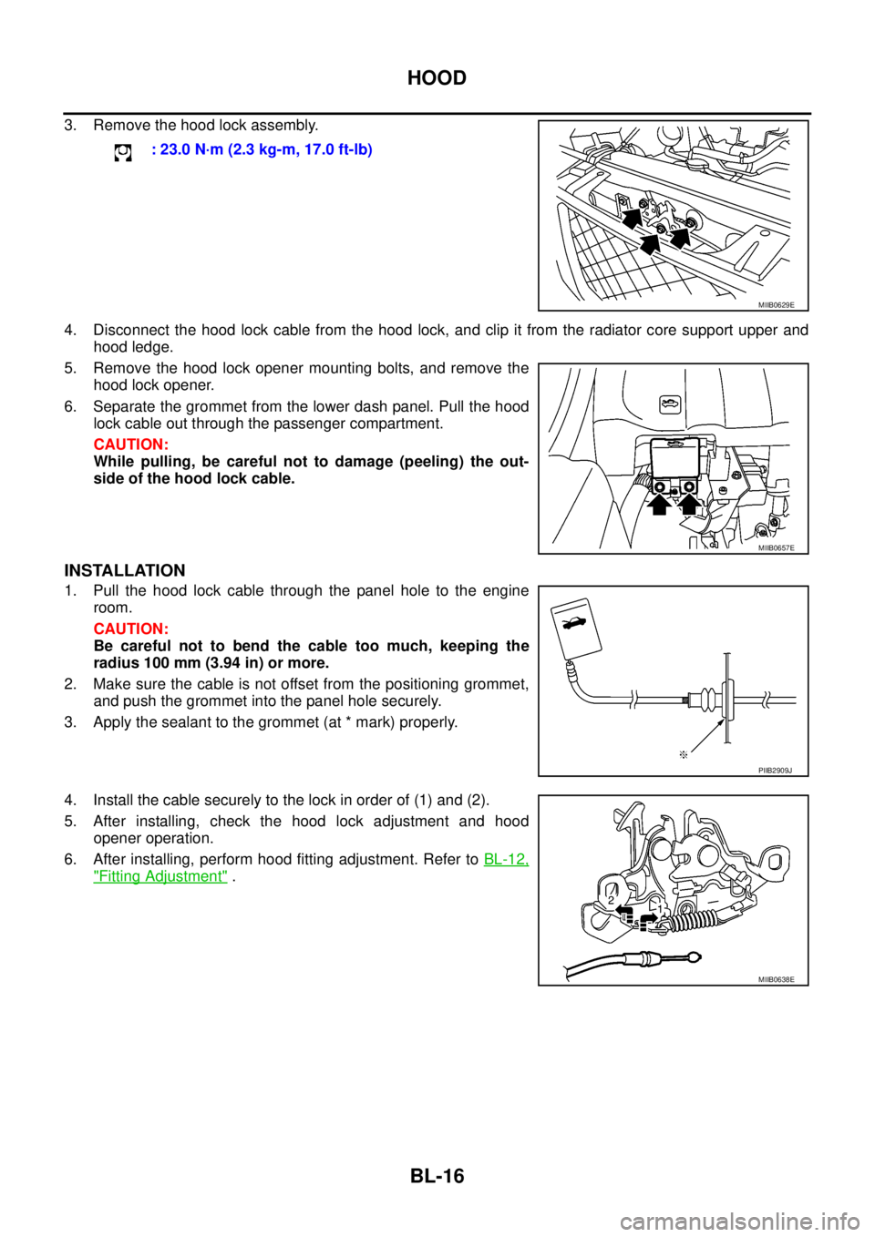
3. Remove the hood lock assembly.
4. Disconnect the hood lock cable from the hood lock, and clip it from the radiator core support upper and
hood ledge.
5. Remove the hood lock opener mounting bolts, and remove the
hood lock opener.
6. Separate the grommet from the lower dash panel. Pull the hood
lock cable out through the passenger compartment.
CAUTION:
While pulling, be careful not to damage (peeling) the out-
side of the hood lock cable.
INSTALLATION
1. Pull the hood lock cable through the panel hole to the engine
room.
CAUTION:
Be careful not to bend the cable too much, keeping the
radius 100 mm (3.94 in) or more.
2. Make sure the cable is not offset from the positioning grommet,
and push the grommet into the panel hole securely.
3. Apply the sealant to the grommet (at * mark) properly.
4. Install the cable securely to the lock in order of (1) and (2).
5. After installing, check the hood lock adjustment and hood
opener operation.
6. After installing, perform hood fitting adjustment. Refer toBL-12,
"Fitting Adjustment". : 23.0 N·m (2.3 kg-m, 17.0 ft-lb)
MIIB0629E
MIIB0657E
PIIB2909J
MIIB0638E
Page 601 of 3171

HOOD
BL-17
C
D
E
F
G
H
J
K
L
MA
B
BL
Hood Lock Control InspectionEIS00BQ1
CAUTION:
If the hood lock cable is bent or deformed, replace it.
1. Make sure that the hood lock secondary latch is properly engaged with the secondary striker with hood's
own weight.
2. Make sure that the hood lock primary latch is securely engaged with the hood striker with hood's own
weight by dropping it from approx. 200 mm (7.87 in) height.
CAUTION:
Do not drop hood from a height of 300 mm (11.81 in) or more.
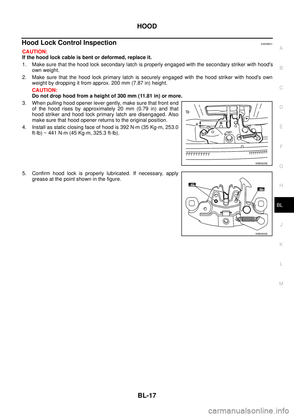
3. When pulling hood opener lever gently, make sure that front end
of the hood rises by approximately 20 mm (0.79 in) and that
hood striker and hood lock primary latch are disengaged. Also
make sure that hood opener returns to the original position.
4. Install as static closing face of hood is 392 N·m (35 Kg-m, 253.0
ft-lb) ~ 441 N·m (45 Kg-m, 325.3 ft-lb).
5. Confirm hood lock is properly lubricated. If necessary, apply
grease at the point shown in the figure.
MIIB0639E
MIIB0640E