Page 178 of 3171

AT-170
1ST POSITION SWITCH
1ST POSITION SWITCH
PFP:31918
CONSULT-II Reference ValueECS00I5W
Diagnostic ProcedureECS00I5X
1.CHECK CAN COMMUNICATION LINE
Perform the self-diagnosis. Refer toAT-80, "
SELF-DIAGNOSTIC RESULT MODE".
Is any malfunction in the CAN communication indicated in the results?
YES >> Check CAN communication line. Refer toAT-91, "DTC U1000 CAN COMMUNICATION LINE".
NO >> GO TO 2.
2.CHECK 1ST POSITION SWITCH CIRCUIT
With CONSULT-II
1. Turn ignition switch ON.
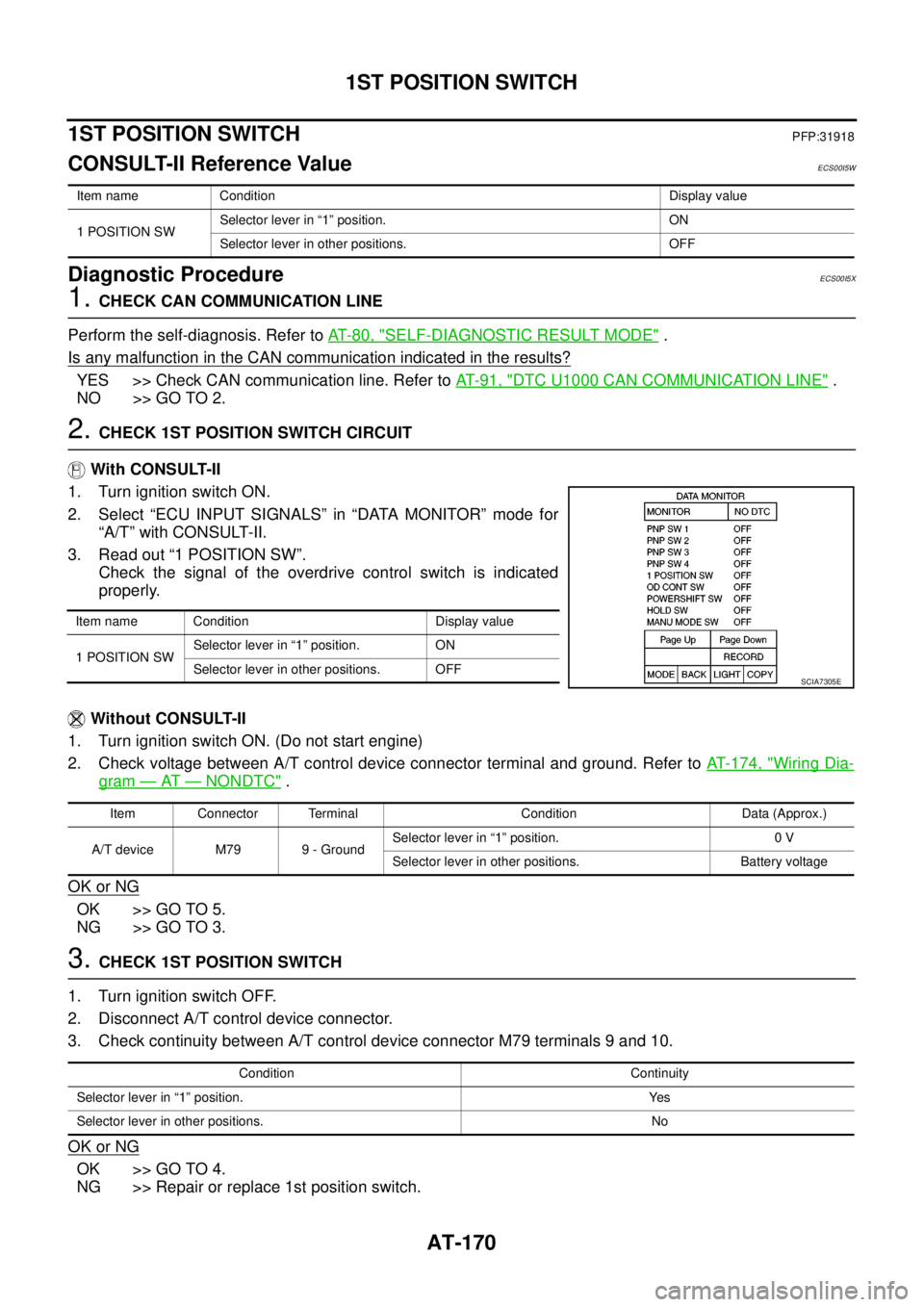
2. Select “ECU INPUT SIGNALS” in “DATA MONITOR” mode for
“A/T” with CONSULT-II.
3. Read out “1 POSITION SW”.
Check the signal of the overdrive control switch is indicated
properly.
Without CONSULT-II
1. Turn ignition switch ON. (Do not start engine)
2. Check voltage between A/T control device connector terminal and ground. Refer toAT- 1 7 4 , "
Wiring Dia-
gram—AT—NONDTC".
OK or NG
OK >> GO TO 5.
NG >> GO TO 3.
3.CHECK 1ST POSITION SWITCH
1. Turn ignition switch OFF.
2. Disconnect A/T control device connector.
3. Check continuity between A/T control device connector M79 terminals 9 and 10.
OK or NG
OK >> GO TO 4.
NG >> Repair or replace 1st position switch.
Item name Condition Display value
1 POSITION SWSelector lever in “1” position. ON
Selector lever in other positions. OFF
Item name Condition Display value
1 POSITION SWSelector lever in “1” position. ON
Selector lever in other positions. OFF
SCIA7305E
Item Connector Terminal Condition Data (Approx.)
A/T device M79 9 - GroundSelector lever in “1” position. 0 V
Selector lever in other positions. Battery voltage
Condition Continuity
Selector lever in “1” position. Yes
Selector lever in other positions. No
Page 180 of 3171

AT-172
OVERDRIVE CONTROL SWITCH
OVERDRIVE CONTROL SWITCH
PFP:25130
CONSULT-II Reference ValueECS00HQY
Diagnostic ProcedureECS00HQZ
1.CHECK CAN COMMUNICATION LINE
Perform the self-diagnosis. Refer toAT-80, "
SELF-DIAGNOSTIC RESULT MODE".
Is any malfunction in the CAN communication indicated in the results?
YES >> Check CAN communication line. Refer toAT-91, "DTC U1000 CAN COMMUNICATION LINE".
NO >> GO TO 2.
2.CHECK OVERDRIVE CONTOROL SWITCH CIRCUIT
With CONSULT-II
1. Turn ignition switch ON.
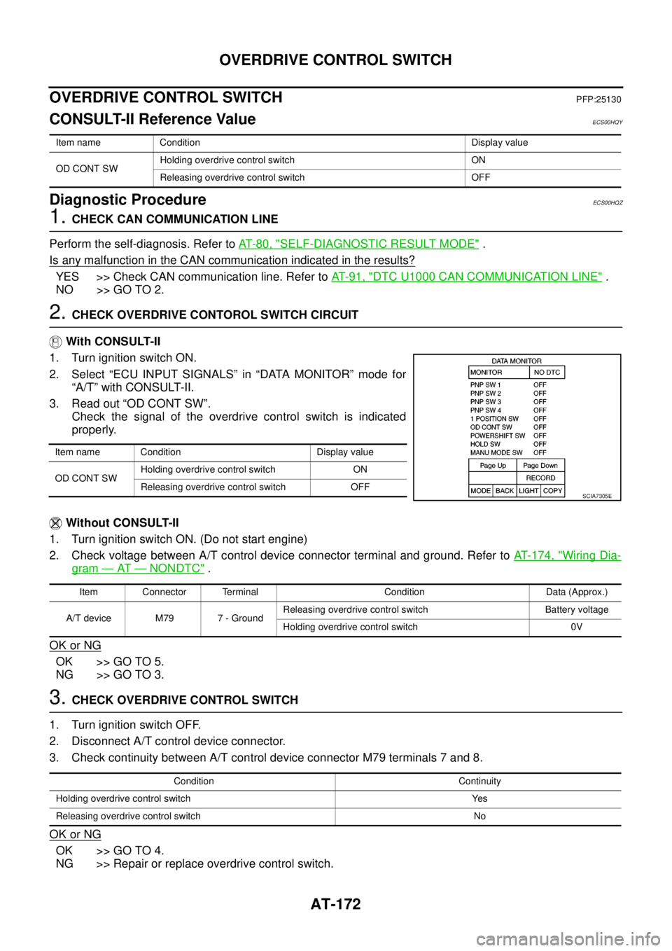
2. Select “ECU INPUT SIGNALS” in “DATA MONITOR” mode for
“A/T” with CONSULT-II.
3. Read out “OD CONT SW”.
Check the signal of the overdrive control switch is indicated
properly.
Without CONSULT-II
1. Turn ignition switch ON. (Do not start engine)
2. Check voltage between A/T control device connector terminal and ground. Refer toAT- 1 7 4 , "
Wiring Dia-
gram—AT—NONDTC".
OK or NG
OK >> GO TO 5.
NG >> GO TO 3.
3.CHECK OVERDRIVE CONTROL SWITCH
1. Turn ignition switch OFF.
2. Disconnect A/T control device connector.
3. Check continuity between A/T control device connector M79 terminals 7 and 8.
OK or NG
OK >> GO TO 4.
NG >> Repair or replace overdrive control switch.
Item name Condition Display value
OD CONT SWHolding overdrive control switch ON
Releasing overdrive control switch OFF
Item name Condition Display value
OD CONT SWHolding overdrive control switch ON
Releasing overdrive control switch OFF
SCIA7305E
Item Connector Terminal Condition Data (Approx.)
A/T device M79 7 - GroundReleasing overdrive control switch Battery voltage
Holding overdrive control switch 0V
Condition Continuity
Holding overdrive control switch Yes
Releasing overdrive control switch No
Page 224 of 3171
AT-216
KEY INTERLOCK CABLE
KEY INTERLOCK CABLE
PFP:34908
Removal and InstallationECS00G33
COMPONENTS
CAUTION:
lInstall key interlock cable in such a way that it will not be damaged by sharp bends, twists or inter-
ference with adjacent parts.
lAfter installing key interlock cable to control device, make sure that casing cap and bracket are
firmly secured in their positions. If casing cap can be removed with an external load of less than
39 N (4.0 kg, 8.8 lb), replace key interlock cable with new one.
SCIA6791E
Page 225 of 3171

KEY INTERLOCK CABLE
AT-217
D
E
F
G
H
I
J
K
L
MA
B
AT
REMOVAL
1. Remove center console. Refer toIP-16, "CENTER CONSOLE".
2. Remove lower instrument panel LH (for LHD models) or lower instrument panel RH (for RHD models) and
cluster lid A. Refer toIP-13, "
LOWER INSTRUMENT PANEL LH",IP-15, "LOWER INSTRUMENT
PANEL RH AND GLOVE BOX",IP-10, "INSTRUMENT PANEL".
3. Unlock slider by squeezing lock tabs on slider from adjuster
holder.
4. Remove casing cap from bracket of control device assembly
and remove interlock rod from adjuster holder.
5. Remove holder from key cylinder and remove key interlock
cable.
INSTALLATION
1. Set key interlock cable to key cylinder and install holder.
2. Turn ignition key to lock position.
3. Set selector lever to “P” position.
4. Insert interlock rod into adjuster holder.
5. Install casing cap to bracket.
6. Move slider in order to secure adjuster holder to interlock rod.
CAUTION:
Do not touch any other areas than slider or apply any force
to slider except in the sliding direction.
7. Install lower instrument panel LH (for LHD models) or lower
instrument panel RH (for RHD models) and cluster lid A. Refer
toIP-13, "
LOWER INSTRUMENT PANEL LH",IP-15, "LOWER
INSTRUMENT PANEL RH AND GLOVE BOX",IP-10,
"INSTRUMENT PANEL".
8. Install center console. Refer toIP-16, "
CENTER CONSOLE".
SCIA6793E
SCIA6900E
SCIA6900E
SCIA1232E
Page 232 of 3171
AT-224
ON-VEHICLE SERVICE
7. Install control valve with TCM in transmission case.
CAUTION:
lMake sure that turbine revolution sensor securely installs
turbine revolution sensor hole.
lHang down revolution sensor harness toward outside so
as not to disturb installation of control valve with TCM.
lAdjust A/T assembly harness connector of control valve
with TCM to terminal hole of transmission case.
lAssemble it so that manual valve cutout is engaged with
manual plate projection.
8. Install bolts A, B and C in control valve with TCM.
9. Tighten bolt 1, 2 and 3 temporarily to prevent dislocation. After
that tighten them in order (1®2®3), and then tighten other
bolts. Tighten control valve with TCM mounting bolts to the
specified torque. Refer toAT- 2 1 8 , "
COMPONENTS".
SCIA5034E
SCIA5142E
Bolt symbol Length [mm (in)] Number of bolts
A 42 (1.65) 5
B 55 (2.17) 6
C 40 (1.57) 1
SCIA5139E
SCIA5140E
Page 233 of 3171
ON-VEHICLE SERVICE
AT-225
D
E
F
G
H
I
J
K
L
MA
B
AT
10. Connect A/T fluid temperature sensor 2 connector.
11. Securely fasten terminal cord assembly and A/T fluid tempera-
ture sensor 2 harness with terminal clips.
12. Connect revolution sensor connector.
13. Securely fasten revolution sensor harness with terminal clips.
14. Install magnets onto oil pan.
SCIA5023E
SCIA5446E
SCIA5024E
SCIA7022E
SCIA5200E
Page 237 of 3171

ON-VEHICLE SERVICE
AT-229
D
E
F
G
H
I
J
K
L
MA
B
AT
3. Connect A/T fluid temperature sensor 2 connector.
4. Securely fasten A/T fluid temperature sensor 2 harness with ter-
minal clip.
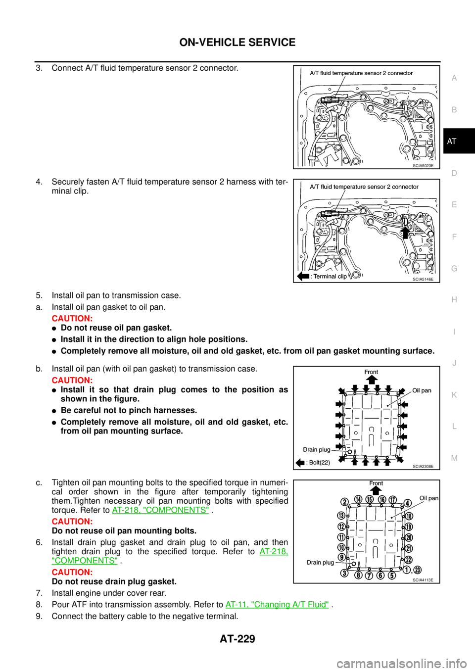
5. Install oil pan to transmission case.
a. Install oil pan gasket to oil pan.
CAUTION:
lDo not reuse oil pan gasket.
lInstall it in the direction to align hole positions.
lCompletely remove all moisture, oil and old gasket, etc. from oil pan gasket mounting surface.
b. Install oil pan (with oil pan gasket) to transmission case.
CAUTION:
lInstall it so that drain plug comes to the position as
shown in the figure.
lBe careful not to pinch harnesses.
lCompletely remove all moisture, oil and old gasket, etc.
from oil pan mounting surface.
c. Tighten oil pan mounting bolts to the specified torque in numeri-
cal order shown in the figure after temporarily tightening
them.Tighten necessary oil pan mounting bolts with specified
torque. Refer toAT- 2 1 8 , "
COMPONENTS".
CAUTION:
Do not reuse oil pan mounting bolts.
6. Install drain plug gasket and drain plug to oil pan, and then
tighten drain plug to the specified torque. Refer toAT-218,
"COMPONENTS".
CAUTION:
Do not reuse drain plug gasket.
7. Install engine under cover rear.
8. Pour ATF into transmission assembly. Refer toAT-11, "
Changing A/T Fluid".
9. Connect the battery cable to the negative terminal.
SCIA5023E
SCIA5146E
SCIA2308E
SCIA4113E
Page 249 of 3171

ON-VEHICLE SERVICE
AT-241
D
E
F
G
H
I
J
K
L
MA
B
AT
Installation
CAUTION:
After completing installation, check A/T fluid leakage, A/T fluid level and A/T position. Refer toAT- 1 2 ,
"Checking A/T Fluid",AT- 2 11 , "Checking of A/T Position".
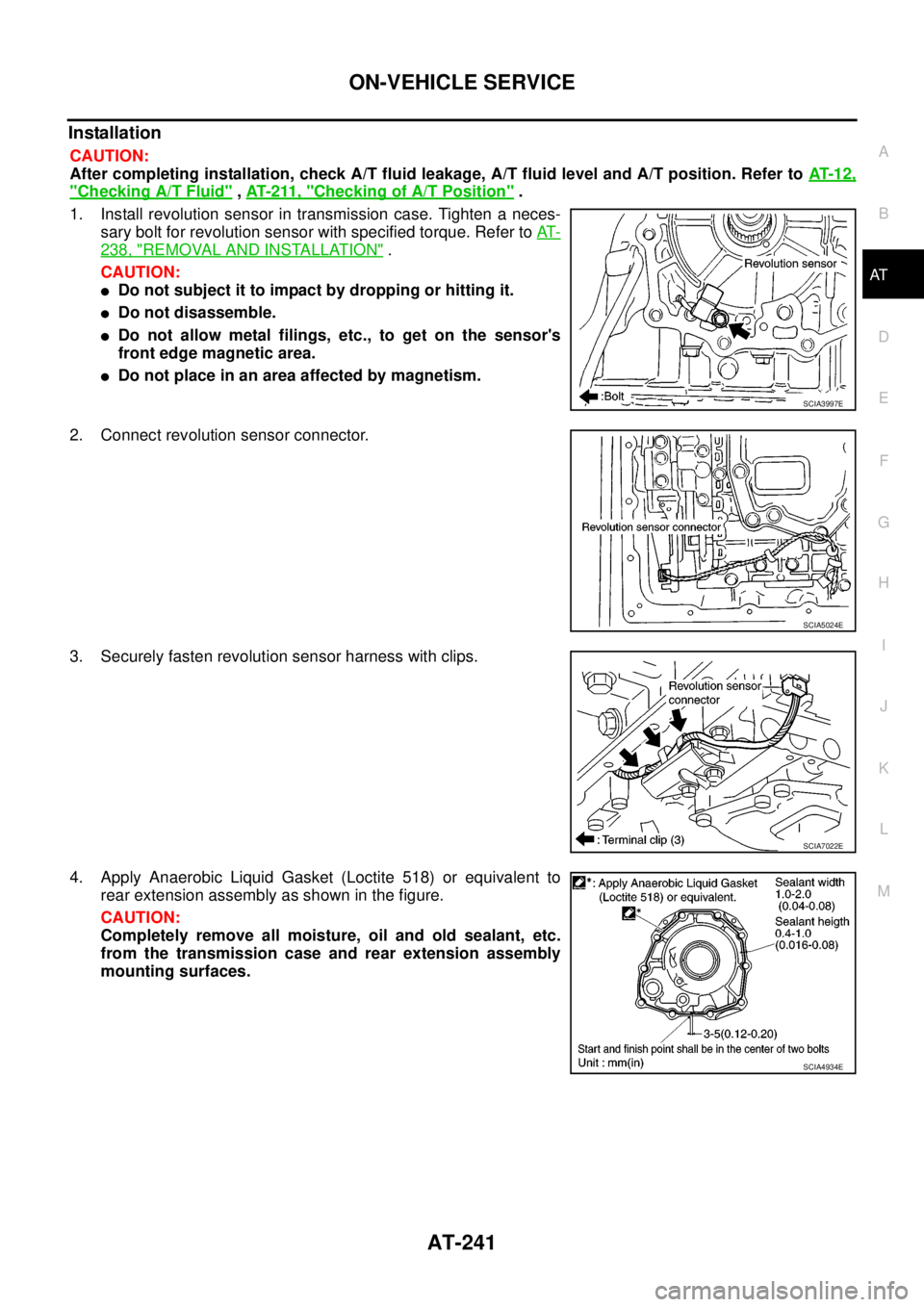
1. Install revolution sensor in transmission case. Tighten a neces-
sary bolt for revolution sensor with specified torque. Refer toAT-
238, "REMOVAL AND INSTALLATION".
CAUTION:
lDo not subject it to impact by dropping or hitting it.
lDo not disassemble.
lDo not allow metal filings, etc., to get on the sensor's
front edge magnetic area.
lDo not place in an area affected by magnetism.
2. Connect revolution sensor connector.
3. Securely fasten revolution sensor harness with clips.
4. Apply Anaerobic Liquid Gasket (Loctite 518) or equivalent to
rear extension assembly as shown in the figure.
CAUTION:
Completely remove all moisture, oil and old sealant, etc.
from the transmission case and rear extension assembly
mounting surfaces.
SCIA3997E
SCIA5024E
SCIA7022E
SCIA4934E