2005 NISSAN NAVARA ECU
[x] Cancel search: ECUPage 94 of 3171

AT-86
TROUBLE DIAGNOSIS
CAN DIAGNOSTIC SUPPORT MONITOR MODE
Operation Procedure
1. PerformAT- 7 9 , "CONSULT-II SETTING PROCEDURE".
2. Touch “CAN DIAG SUPPORT MNTR”. Refer toLAN-15, "
CAN
Diagnostic Support Monitor".
DTC WORK SUPPORT MODE
Operation Procedure
1. PerformAT- 7 9 , "CONSULT-II SETTING PROCEDURE".
2. Touch “DTC WORK SUPPORT”.
START RLY MON — —
NEXT GR POSI — —
SHIFT MODE — —
MANU GR POSI — —
VEHICLE SPEED (km/h) — X Vehicle speed recognized by TCM.
Vo l ta g e (V ) — —Displays the value measured by the voltage
probe.
Frequency (Hz) — —
The value measured by the pulse probe is dis-
played. DUTY-HI (high) (%) — —
DUTY-LOW (low) (%) — —
PLS WIDTH-HI (ms) — —
PLS WIDTH-LOW (ms) — —Monitored item (Unit)Monitor Item Selection
Remarks ECU
INPUT
SIGNALSMAIN SIG-
NALSSELEC-
TION
FROM
MENU
BCIA0031E
BCIA0031E
Page 98 of 3171
AT-90
TROUBLE DIAGNOSIS
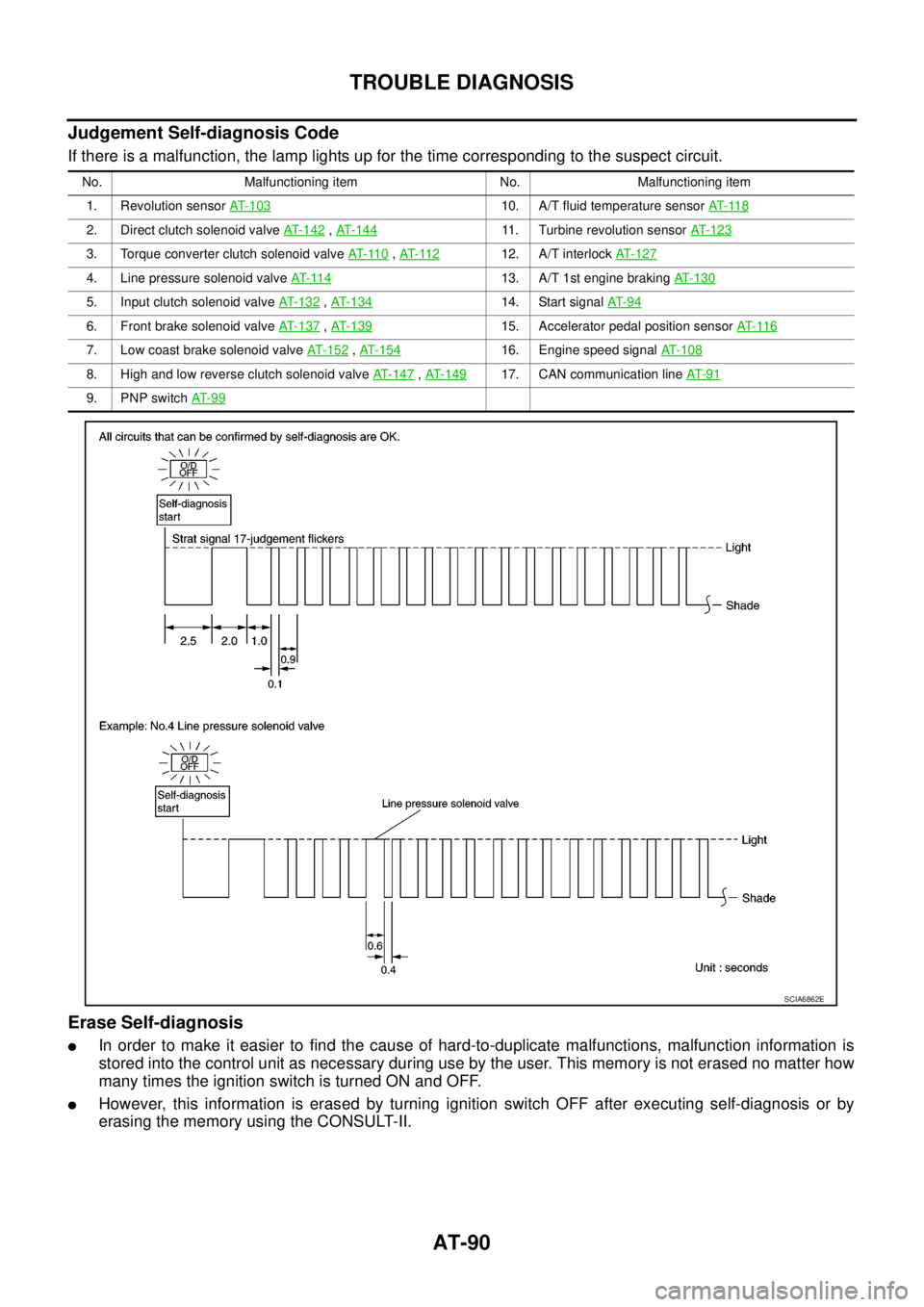
Judgement Self-diagnosis Code
If there is a malfunction, the lamp lights up for the time corresponding to the suspect circuit.
Erase Self-diagnosis
lIn order to make it easier to find the cause of hard-to-duplicate malfunctions, malfunction information is
stored into the control unit as necessary during use by the user. This memory is not erased no matter how
many times the ignition switch is turned ON and OFF.
lHowever, this information is erased by turning ignition switch OFF after executing self-diagnosis or by
erasing the memory using the CONSULT-II.
No. Malfunctioning item No. Malfunctioning item
1. Revolution sensorAT- 1 0 3
10. A/T fluid temperature sensorAT- 11 8
2. Direct clutch solenoid valveAT- 1 4 2,AT-14411. Turbine revolution sensorAT- 1 2 3
3. Torque converter clutch solenoid valveAT- 11 0,AT- 11 212. A/T interlockAT-127
4. Line pressure solenoid valveAT- 11 413. A/T 1st engine brakingAT-130
5. Input clutch solenoid valveAT- 1 3 2,AT- 1 3 414. Start signalAT- 9 4
6. Front brake solenoid valveAT-137,AT- 1 3 915. Accelerator pedal position sensorAT- 11 6
7. Low coast brake solenoid valveAT- 1 5 2,AT- 1 5 416. Engine speed signalAT-108
8. High and low reverse clutch solenoid valveAT-147,AT- 1 4 917. CAN communication lineAT- 9 1
9. PNP switchAT- 9 9
SCIA6862E
Page 102 of 3171

AT-94
DTC P0615 START SIGNAL CIRCUIT
DTC P0615 START SIGNAL CIRCUIT
PFP:25230
DescriptionECS00FXI
TCM prohibits cranking other than at “P” or “N” position.
CONSULT-II Reference ValueECS00FXJ
On Board Diagnosis LogicECS00FXK
Diagnostic trouble code “P0615 STARTER RELAY/CIRC” with CONSULT-II or 14th judgement flicker without
CONSULT-II is detected when starter relay is switched ON other than at “P” or “N” position. (Or when switched
OFF at “P” or “N” position).
Possible CauseECS00FXL
lHarness or connectors
(starter relay and TCM circuit is open or shorted.)
lstarter relay
DTC Confirmation ProcedureECS00FXM
CAUTION:
Always drive vehicle at a safe speed.
NOTE:
If “DTC Confirmation Procedure” has been previously performed, always turn ignition switch OFF and
wait at least 10 seconds before performing the next test.
After the repair, perform the following procedure to confirm the malfunction is eliminated.
WITH CONSULT-II
1. Turn ignition switch ON. (Do not start engine.)
2. Select “SELECTION FROM MENU” in “DATA MONITOR” mode
for “A/T” with CONSULT-II and check monitor “STARTER
RELAY” ON/OFF.
3. Start engine.
4. Drive vehicle for at least 2 consecutive seconds.
5. If DTC is detected, go toAT-96, "
Diagnostic Procedure".
WITHOUT CONSULT-II
1. Start engine.
2. Drive vehicle for at least 2 consecutive seconds.
3. Perform self-diagnosis. Refer toAT-89, "
Diagnostic Procedure Without CONSULT-II".
4. If DTC is detected, go toAT-96, "
Diagnostic Procedure".
Item name Condition Display value
STARTER RELAYSelector lever in “N” or “P” position. ON
Selector lever in other positions. OFF
BCIA0031E
Page 106 of 3171
AT-98
DTC P0700 TCM
DTC P0700 TCM
PFP:31036
DescriptionECS00FXP
TCM consists of a microcomputer and connectors for signal input and output and for power supply. TCM con-
trols A/T.
On Board Diagnosis LogicECS00FXQ
Diagnostic trouble code “P0700 TCM” with CONSULT-II is detected when TCM is malfunctioning.
Possible CauseECS00FXR
TCM
DTC Confirmation ProcedureECS00FXS
NOTE:
If “DTC Confirmation Procedure” has been previously performed, always turn ignition switch OFF and
wait at least 10 seconds before performing the next test.
After the repair, perform the following procedure to confirm the malfunction is eliminated.
WITH CONSULT-II
1. Turn ignition switch ON. (Do not start engine.)
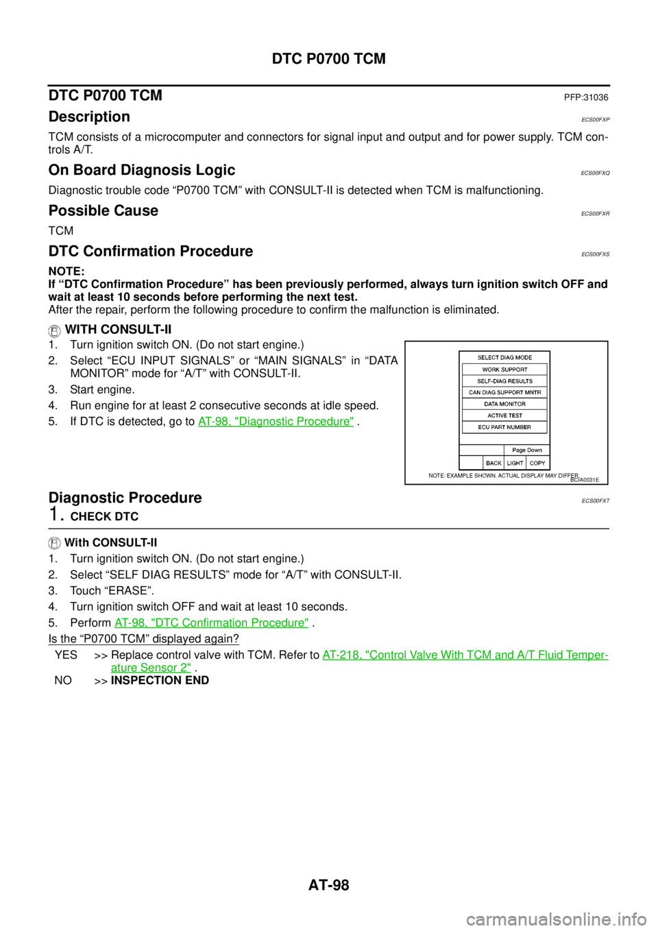
2. Select “ECU INPUT SIGNALS” or “MAIN SIGNALS” in “DATA
MONITOR” mode for “A/T” with CONSULT-II.
3. Start engine.
4. Run engine for at least 2 consecutive seconds at idle speed.
5. If DTC is detected, go toAT-98, "
Diagnostic Procedure".
Diagnostic ProcedureECS00FXT
1.CHECK DTC
With CONSULT-II
1. Turn ignition switch ON. (Do not start engine.)
2. Select “SELF DIAG RESULTS” mode for “A/T” with CONSULT-II.
3. Touch “ERASE”.
4. Turn ignition switch OFF and wait at least 10 seconds.
5. PerformAT- 9 8 , "
DTC Confirmation Procedure".
Is the
“P0700 TCM”displayed again?
YES >> Replace control valve with TCM. Refer toAT- 2 1 8 , "Control Valve With TCM and A/T Fluid Temper-
ature Sensor 2".
NO >>INSPECTION END
BCIA0031E
Page 107 of 3171
DTC P0705 PARK/NEUTRAL POSITION SWITCH
AT-99
D
E
F
G
H
I
J
K
L
MA
B
AT
DTC P0705 PARK/NEUTRAL POSITION SWITCHPFP:32006
DescriptionECS00FXU
lPNP switch includes a transmission range switch.
lThe transmission range switch detects the selector lever position and sends a signal to TCM.
CONSULT-II Reference ValueECS00FXV
On Board Diagnosis LogicECS00FXW
Diagnostic trouble code “P0705 PNP SW/CIRC” with CONSULT-II or 9th judgement flicker without CONSULT-
II is detected under the following conditions.
lWhen TCM does not receive the correct voltage signal from PNP switches 1, 2, 3 and 4 based on the gear
position.
lWhen no other positions but “P” position is detected from “N” position.
Possible CauseECS00FXX
lHarness or connectors
PNP switches 1, 2, 3 and 4 and TCM circuit is open or shorted.
lPNPswitches1,2,3and4
DTC Confirmation ProcedureECS00FXY
CAUTION:
Always drive vehicle at a safe speed.
NOTE:
If “DTC Confirmation Procedure” has been previously performed, always turn ignition switch OFF and
wait at least 10 seconds before performing the next test.
After the repair, perform the following procedure to confirm the malfunction is eliminated.
WITH CONSULT-II
1. Turn ignition switch ON. (Do not start engine.)
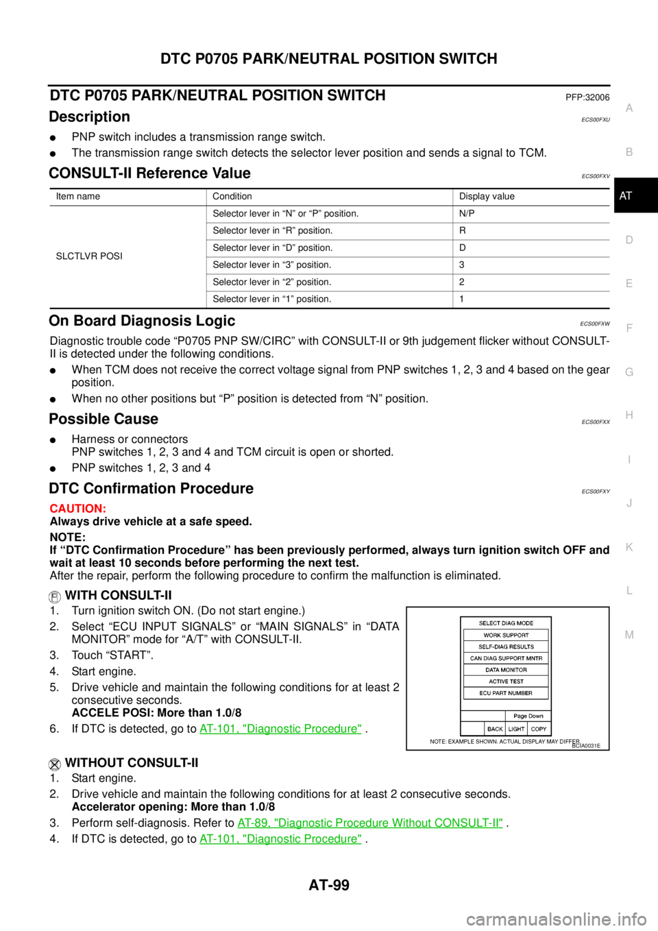
2. Select “ECU INPUT SIGNALS” or “MAIN SIGNALS” in “DATA
MONITOR” mode for “A/T” with CONSULT-II.
3. Touch “START”.
4. Start engine.
5. Drive vehicle and maintain the following conditions for at least 2
consecutive seconds.
ACCELE POSI: More than 1.0/8
6. If DTC is detected, go toAT- 1 0 1 , "
Diagnostic Procedure".
WITHOUT CONSULT-II
1. Start engine.
2. Drive vehicle and maintain the following conditions for at least 2 consecutive seconds.
Accelerator opening: More than 1.0/8
3. Perform self-diagnosis. Refer toAT-89, "
Diagnostic Procedure Without CONSULT-II".
4. If DTC is detected, go toAT- 1 0 1 , "
Diagnostic Procedure".
Item name Condition Display value
SLCTLVR POSISelector lever in “N” or “P” position. N/P
Selector lever in “R” position. R
Selector lever in “D” position. D
Selector lever in “3” position. 3
Selector lever in “2” position. 2
Selector lever in “1” position. 1
BCIA0031E
Page 111 of 3171
DTC P0720 VEHICLE SPEED SENSOR A/T (REVOLUTION SENSOR)
AT-103
D
E
F
G
H
I
J
K
L
MA
B
AT
DTC P0720 VEHICLE SPEED SENSOR A/T (REVOLUTION SENSOR)PFP:32702
DescriptionECS00FY1
Revolution sensor detects the revolution of the idler gear parking pawl lock gear and emits a pulse signal. The
pulse signal is sent to TCM which converts it into vehicle speed.
CONSULT-II Reference ValueECS00FY2
On Board Diagnosis LogicECS00FY3
Diagnostic trouble code “P0720 VEH SPD SEN/CIR AT” with CONSULT-II or 1st judgement flicker without
CONSULT-II is detected under the following conditions.
lWhen TCM does not receive the proper voltage signal from the sensor.
lAfter ignition switch is turned ON, irregular signal input from vehicle speed sensor MTR before the vehicle
starts moving.
Possible CauseECS00FY4
lHarness or connectors
(The sensor circuit is open or shorted.)
lRevolution sensor
lVehicle speed sensor MTR
DTC Confirmation ProcedureECS00FY5
CAUTION:
lAlways drive vehicle at a safe speed.
lBe careful not to rev engine into the red zone on the tachometer.
NOTE:
If “DTC Confirmation Procedure” has been previously performed, always turn ignition switch OFF and
wait at least 10 seconds before performing the next test.
After the repair, perform the following procedure to confirm the malfunction is eliminated.
WITH CONSULT-II
1. Turn ignition switch ON. (Do not start engine.)
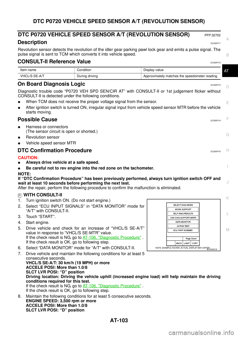
2. Select “ECU INPUT SIGNALS” in “DATA MONITOR” mode for
“A/T” with CONSULT-II.
3. Touch “START”.
4. Start engine.
5. Drive vehicle and check for an increase of “VHCL/S SE-A/T”
value in response to “VHCL/S SE-MTR” value.
If the check result is NG, go toAT- 1 0 6 , "
Diagnostic Procedure".
If the check result is OK, go to following step.
6. Select “DATA MONITOR” mode for “A/T” with CONSULT-II.
7. Drive vehicle and maintain the following conditions for at least 5
consecutive seconds.
VHCL/S SE-A/T: 30 km/h (19 MPH) or more
ACCELE POSI: More than 1.0/8
SLCT LVR POSI: “D” position
Driving location: Driving the vehicle uphill (increased engine load) will help maintain the driving
conditions required for this test.
If the check result is NG, go toAT- 1 0 6 , "
Diagnostic Procedure".
If the check result is OK, go to following step.
8. Maintain the following conditions for at least 5 consecutive seconds.
ENGINE SPEED: 3,500 rpm or more
ACCELE POSI: More than 1.0/8
SLCT LVR POSI: “D” position
Item name Condition Display value
VHCL/S SE-A/T During driving Approximately matches the speedometer reading.
BCIA0031E
Page 112 of 3171

AT-104
DTC P0720 VEHICLE SPEED SENSOR A/T (REVOLUTION SENSOR)
Driving location: Driving the vehicle uphill (increased engine load) will help maintain the driving
conditions required for this test.
If is detected, go toAT- 1 0 6 , "
Diagnostic Procedure".
WITHOUT CONSULT-II
1. Start engine.
2. Drive vehicle and maintain the following conditions for at least 5 consecutive seconds.
Vehicle speed: 30 km/h (19 MPH) or more
Accelerator opening: More than 1.0/8
Selector lever position: “D” position
Driving location: Driving the vehicle uphill (increased engine load) will help maintain the driving
conditions required for this test.
3. Perform self-diagnosis. Refer toAT-89, "
Diagnostic Procedure Without CONSULT-II".
4. If DTC is detected, go toAT- 1 0 6 , "
Diagnostic Procedure".
Page 114 of 3171
AT-106
DTC P0720 VEHICLE SPEED SENSOR A/T (REVOLUTION SENSOR)
Diagnostic Procedure
ECS00FY7
1.CHECK INPUT SIGNAL
With CONSULT-II
1. Turn ignition switch ON. (Do not start engine)
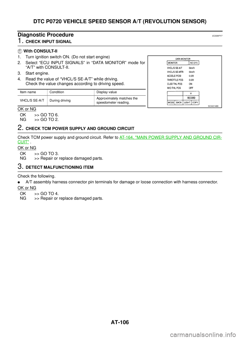
2. Select “ECU INPUT SIGNALS” in “DATA MONITOR” mode for
“A/T” with CONSULT-II.
3. Start engine.
4. Read the value of “VHCL/S SE-A/T” while driving.
Check the value changes according to driving speed.
OK or NG
OK >> GO TO 6.
NG >> GO TO 2.
2.CHECK TCM POWER SUPPLY AND GROUND CIRCUIT
Check TCM power supply and ground circuit. Refer toAT- 1 6 4 , "
MAIN POWER SUPPLY AND GROUND CIR-
CUIT".
OK or NG
OK >> GO TO 3.
NG >> Repair or replace damaged parts.
3.DETECT MALFUNCTIONING ITEM
Check the following.
lA/T assembly harness connector pin terminals for damage or loose connection with harness connector.
OK or NG
OK >> GO TO 4.
NG >> Repair or replace damaged parts.
Item name Condition Display value
VHCL/S SE-A/T During drivingApproximately matches the
speedometer reading.
SCIA2148E