Page 3075 of 4323
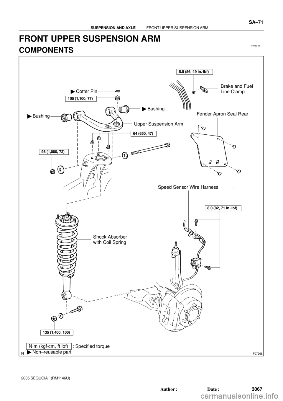
SA183±05
F07268
Upper Suspension Arm
N´m (kgf´cm, ft´lbf)
: Specified torque
� Non±reusable part
Brake and Fuel
Line Clamp
Fender Apron Seal Rear
Speed Sensor Wire Harness � Bushing
� Bushing � Cotter Pin
105 (1,100, 77)
64 (650, 47)
98 (1,000, 72)
135 (1,400, 100)
Shock Absorber
with Coil Spring
8.0 (82, 71 in.´lbf)
5.5 (56, 49 in.´lbf)
± SUSPENSION AND AXLEFRONT UPPER SUSPENSION ARM
SA±71
3067 Author�: Date�:
2005 SEQUOIA (RM1146U)
FRONT UPPER SUSPENSION ARM
COMPONENTS
Page 3076 of 4323
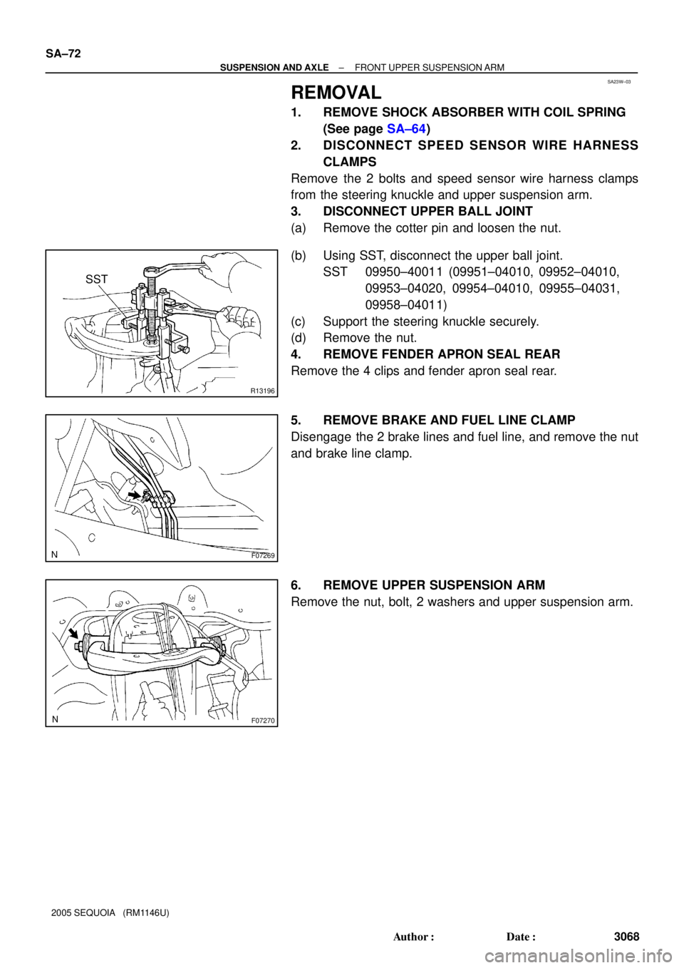
SA23W±03
R13196
SST
F07269
F07270
SA±72
± SUSPENSION AND AXLEFRONT UPPER SUSPENSION ARM
3068 Author�: Date�:
2005 SEQUOIA (RM1146U)
REMOVAL
1. REMOVE SHOCK ABSORBER WITH COIL SPRING
(See page SA±64)
2. DISCONNECT SPEED SENSOR WIRE HARNESS
CLAMPS
Remove the 2 bolts and speed sensor wire harness clamps
from the steering knuckle and upper suspension arm.
3. DISCONNECT UPPER BALL JOINT
(a) Remove the cotter pin and loosen the nut.
(b) Using SST, disconnect the upper ball joint.
SST 09950±40011 (09951±04010, 09952±04010,
09953±04020, 09954±04010, 09955±04031,
09958±04011)
(c) Support the steering knuckle securely.
(d) Remove the nut.
4. REMOVE FENDER APRON SEAL REAR
Remove the 4 clips and fender apron seal rear.
5. REMOVE BRAKE AND FUEL LINE CLAMP
Disengage the 2 brake lines and fuel line, and remove the nut
and brake line clamp.
6. REMOVE UPPER SUSPENSION ARM
Remove the nut, bolt, 2 washers and upper suspension arm.
Page 3078 of 4323

INSTALLATION
1. INSTALL UPPER SUSPENSION ARM
Install the upper suspension arm with the 2")
SA187±06
SA±74
± SUSPENSION AND AXLEFRONT UPPER SUSPENSION ARM
3070 Author�: Date�:
2005 SEQUOIA (RM1146U)
INSTALLATION
1. INSTALL UPPER SUSPENSION ARM
Install the upper suspension arm with the 2 washers, bolt and nut.
Torque: 98 N´m (1,000 kgf´cm, 72 ft´lbf)
HINT:
After stabilizing the suspension, torque the nut.
2. INSTALL BRAKE AND FUEL LINE CLAMP
Torque: 5.5 N´m (56 kgf´cm, 49 in.´lbf)
3. INSTALL FENDER APRON SEAL REAR
4. CONNECT UPPER BALL JOINT
(a) Connect the upper ball joint to the upper suspension arm.
(b) Install the nut and a new cotter pin.
If the holes for the cotter pin are not aligned, tighten the nut further up to 60°.
Torque: 105 N´m (1,100 kgf´cm, 77 ft´lbf)
5. CONNECT SPEED SENSOR WIRE HARNESS CLAMPS
Torque: 8.0 N´m (82 kgf´cm, 71 in.´lbf)
6. INSTALL SHOCK ABSORBER WITH COIL SPRING (See page SA±70)
7. CHECK FRONT WHEEL ALIGNMENT (See page SA±4)
8. PERFORM ZERO POINT CALIBRATION OF STEERING ANGLE, MASTER CYLINDER PRES-
SURE, YAW RATE AND DECELERATION SENSORS (See page DI±897)
Page 3079 of 4323
SA17M±06
F07272
No. 2 Spring Bumper
No. 1 Spring Bumper
N´m (kgf´cm, ft´lbf) : Specified torque
Non±reusable part
�
* For use with SST
31 (315, 23)
*23 (235, 17)
165 (1,700, 122)
130 (1,350, 96)
91 (930, 67)
91 (930, 67)
165 (1,700, 122)
Power Steering Gear
� Cotter Pin
� Cotter Pin
31 (315, 23)
*23 (235, 17)
135 (1,400, 100)
130 (1,325, 96)
Cam
Cam PlateCam
� No. 2 Bushing
� No. 1 Bushing
Lower Suspension Arm
Stabilizer
Bar Link
159 (1,621, 117)
� Cotter Pin
69 (700, 51)
Retainer
Retainer Bushing
Stabilizer Bar
Stabilizer Bar
Bracket Bushing
37 (377, 27)
130 (1,325, 96)�19 (190, 14)
± SUSPENSION AND AXLEFRONT LOWER SUSPENSION ARM
SA±75
3071 Author�: Date�:
2005 SEQUOIA (RM1146U)
FRONT LOWER SUSPENSION ARM
COMPONENTS
Page 3080 of 4323
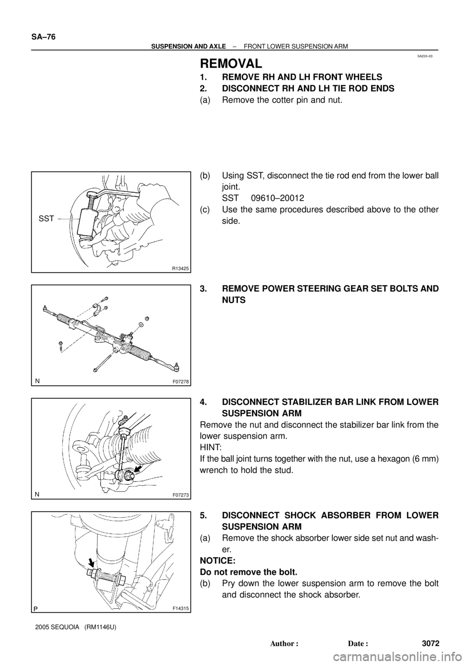
SA23X±03
R13425
SST
F07278
F07273
F14315
SA±76
± SUSPENSION AND AXLEFRONT LOWER SUSPENSION ARM
3072 Author�: Date�:
2005 SEQUOIA (RM1146U)
REMOVAL
1. REMOVE RH AND LH FRONT WHEELS
2. DISCONNECT RH AND LH TIE ROD ENDS
(a) Remove the cotter pin and nut.
(b) Using SST, disconnect the tie rod end from the lower ball
joint.
SST 09610±20012
(c) Use the same procedures described above to the other
side.
3. REMOVE POWER STEERING GEAR SET BOLTS AND
NUTS
4. DISCONNECT STABILIZER BAR LINK FROM LOWER
SUSPENSION ARM
Remove the nut and disconnect the stabilizer bar link from the
lower suspension arm.
HINT:
If the ball joint turns together with the nut, use a hexagon (6 mm)
wrench to hold the stud.
5. DISCONNECT SHOCK ABSORBER FROM LOWER
SUSPENSION ARM
(a) Remove the shock absorber lower side set nut and wash-
er.
NOTICE:
Do not remove the bolt.
(b) Pry down the lower suspension arm to remove the bolt
and disconnect the shock absorber.
Page 3081 of 4323
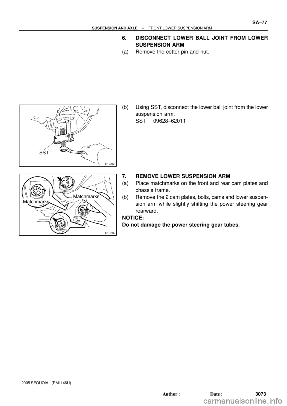
R12863
SST
R13282
MatchmarksMatchmarks
± SUSPENSION AND AXLEFRONT LOWER SUSPENSION ARM
SA±77
3073 Author�: Date�:
2005 SEQUOIA (RM1146U)
6. DISCONNECT LOWER BALL JOINT FROM LOWER
SUSPENSION ARM
(a) Remove the cotter pin and nut.
(b) Using SST, disconnect the lower ball joint from the lower
suspension arm.
SST 09628±62011
7. REMOVE LOWER SUSPENSION ARM
(a) Place matchmarks on the front and rear cam plates and
chassis frame.
(b) Remove the 2 cam plates, bolts, cams and lower suspen-
sion arm while slightly shifting the power steering gear
rearward.
NOTICE:
Do not damage the power steering gear tubes.
Page 3084 of 4323

INSTALLATION
1. INSTALL LOWER SUSPENSION ARM TO")
SA23Y±05
R13282
MatchmarksMatchmarks
F07278
AC
B SA±80
± SUSPENSION AND AXLEFRONT LOWER SUSPENSION ARM
3076 Author�: Date�:
2005 SEQUOIA (RM1146U)
INSTALLATION
1. INSTALL LOWER SUSPENSION ARM TO CHASSIS
FRAME
Install the lower suspension arm with the 2 cams, bolts and cam
plates while slightly shifting the power steering gear rearward.
Torque: 130 N´m (1,325 kgf´cm, 96 ft´lbf)
NOTICE:
Do not damage the power steering gear tubes.
HINT:
After stabilizing the suspension, align the matchmarks on the
front and rear cam plates and chassis frame, and torque the
bolts.
2. CONNECT LOWER BALL JOINT TO LOWER SUSPEN-
SION ARM
Connect the lower ball joint and install the nut and a new cotter
pin.
Torque: 159 N´m (1,621 kgf´cm, 117 ft´lbf)
If the holes for the cotter pin are not aligned, tighten the nut fur-
ther up to 60°.
3. CONNECT SHOCK ABSORBER TO LOWER SUSPEN-
SION ARM
Torque: 135 N´m (1,400 kgf´cm, 100 ft´lbf)
4. CONNECT STABILIZER BAR LINK TO LOWER SUS-
PENSION ARM
Torque: 69 N´m (700 kgf´cm, 51 ft´lbf)
HINT:
If the ball joint turns together with the nut, use a hexagon (6 mm)
wrench to hold the stud.
5. INSTALL POWER STEERING GEAR
Torque:
A bolt: 165 N´m (1,700 kgf´cm, 122 ft´lbf)
B nut: 130 N´m (1,350 kgf´cm, 96 ft´lbf)
C bolt and nut: 165 N´m (1,700 kgf´cm, 122 ft´lbf)
6. CONNECT RH AND LH TIE ROD ENDS
Connect the RH and LH tie rod ends to the lower ball joints with
the nuts and new cotter pins.
Torque: 91 N´m (930 kgf´cm, 67 ft´lbf)
If the holes for the cotter pin are not aligned, tighten the nut fur-
ther up to 60°.
7. INSTALL RH AND LH FRONT WHEELS
Torque: 110 N´m (1,150 kgf´cm, 83 ft´lbf)
8. CHECK FRONT WHEEL ALIGNMENT (See page
SA±4)
9. PERFORM ZERO POINT CALIBRATION OF STEER-
ING ANGLE, MASTER CYLINDER PRESSURE, YAW
RATE AND DECELERATION SENSORS (See page
DI±897)
Page 3085 of 4323
SA23Z±04
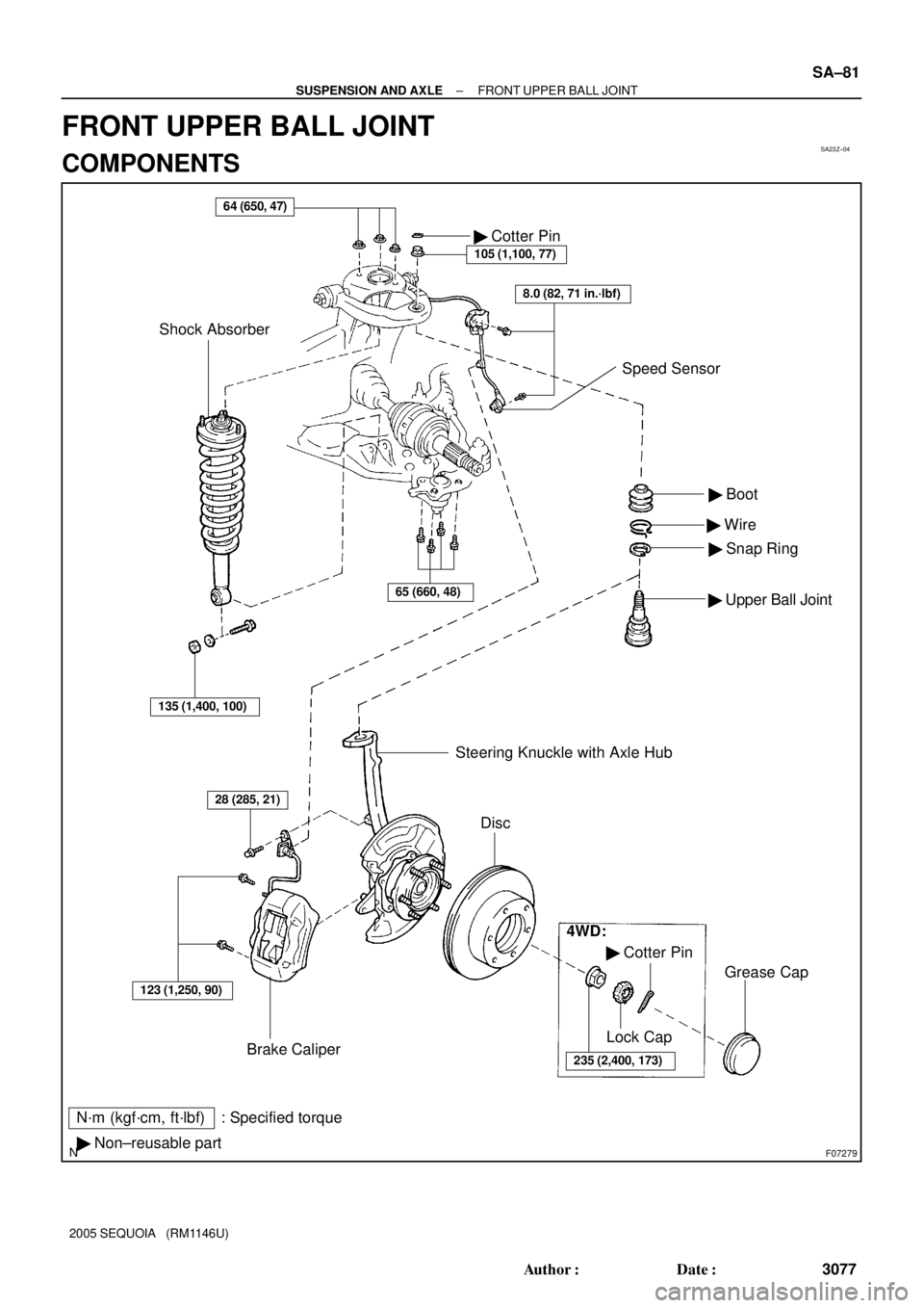
F07279
N´m (kgf´cm, ft´lbf) : Specified torque
� Non±reusable part� Boot
� Wire
� Snap Ring
� Upper Ball Joint
64 (650, 47)
Brake Caliper� Cotter Pin
105 (1,100, 77)
Shock Absorber
123 (1,250, 90)
28 (285, 21)
Steering Knuckle with Axle Hub
Disc
4WD:
� Cotter Pin
235 (2,400, 173)
Lock Cap
Grease Cap
8.0 (82, 71 in.´lbf)
Speed Sensor
135 (1,400, 100)
65 (660, 48)
± SUSPENSION AND AXLEFRONT UPPER BALL JOINT
SA±81
3077 Author�: Date�:
2005 SEQUOIA (RM1146U)
FRONT UPPER BALL JOINT
COMPONENTS