Page 148 of 4323
 Cylinder block
Cylinder head surface warpage Maximum
Cylinder bore diameter STD Mark 1
Mark 2
Mark 3
Maxi")
SS±6
± SERVICE SPECIFICATIONSENGINE MECHANICAL
148 Author�: Date�:
2005 SEQUOIA (RM1146U) Cylinder block
Cylinder head surface warpage Maximum
Cylinder bore diameter STD Mark 1
Mark 2
Mark 3
Maximum STD
O/S 050
Main bearing cap bolt tension portion diameter STD
Minimum0.07 mm (0.0028 in.)
94.002 to 94.010 mm (3.7009 to 3.7012 in.)
94.010 to 94.023 mm (3.7012 to 3.7017 in.)
94.023 to 94.031 mm (3.7017 to 3.7020 in.)
94.231 mm (3.7099 in.)
94.731 mm (3.7296 in.)
10.760 to 10.970 mm (0.4236 to 0.4319 in.)
10.40 mm (0.4094 in.)
Piston and
piston ringPiston diameter STD Mark 1
Mark 2
Mark 3
O/S 0.50
Piston oil clearance STD
Maximum
Piston ring groove clearance No.1
No.2
Piston ring end gap STD No.1
No.2
Oil
Maximum No.1
No.2
Oil93.902 to 93.935 mm (3.6969 to 3.6982 in.)
93.912 to 93.940 mm (3.6973 to 3.6984 in.)
93.920 to 93.950 mm (3.6976 to 3.6988 in.)
94.402 to 94.450 mm (3.7166 to 3.7185 in.)
0.030 to 0.071 mm (0.0012 to 0.0028 in.)
0.13 mm (0.0051 in.)
0.030 to 0.080 mm (0.0012 to 0.0031 in.)
0.020 to 0.060 mm (0.0008 to 0.0024 in.)
0.300 to 0.400 mm (0.0118 to 0.0157 in.)
0.400 to 0.550 mm (0.0157 to 0.0217 in.)
0.130 to 0.380 mm (0.0051 to 0.0150 in.)
1.10 mm (0.0433 in.)
1.30 mm (0.0511 in.)
0.09 mm (0.0354 in.)
Connecting rodThrust clearance STD
Maximum
Connecting rod thickness
Connecting rod oil clearance STD
Maximum
Connecting rod bearing center wall thickness
(Reference) Mark 2
Mark 3
Mark 4
Mark 5
Mark 6
Mark 7
Rod bend Maximum per 100 mm (3.94 in.)
Rod twist Maximum per 100 mm (3.94 in.)
Bushing inside diameter
Piston pin diameter
Bushing oil clearance STD
Maximum
Connecting rod bolt tension portion diameter STD
Minimum0.160 to 0.290 mm (0.0063 to 0.0138 in.)
0.35 mm (0.0138 in.)
22.880 to 22.920 mm (0.9008 to 0.9024 in.)
0.021 to 0.047 mm (0.0008 to 0.0019 in.)
0.059 mm (0.0023 in.)
1.487 to 1.490 mm (0.0585 to 0.0587 in.)
1.490 to 1.493 mm (0.0587 to 0.0588 in.)
1.493 to 1.496 mm (0.0588 to 0.0589 in.)
1.496 to 1.499 mm (0.0589 to 0.0590 in.)
1.499 to 1.502 mm (0.0590 to 0.0591 in.)
1.502 to 1.505 mm (0.0591 to 0.0593 in.)
0.05 mm (0.0020 in.)
0.15 mm (0.0059 in.)
22.005 to 22.014 mm (0.8663 to 0.8667 in.)
21.997 to 22.009 mm (0.8660 to 0.8664 in.)
0.005 to 0.011 mm (0.0002 to 0.0004 in)
0.05 mm (0.0020 in.)
7.200 to 7.300 mm (0.2835 to 0.2874 in.)
7.00 mm (0.2756 in.)
CrankshaftThrust clearance STD
Maximum
Thrust washer thickness
Main journal bore diameter on cylinder block
(with main bearing)
Main journal oil clearance STD No.1, No.5
others
Maximum
Main journal diameter0.020 to 0.220 mm (0.0008 to 0.0087 in.)
0.30 mm (0.0118 in.)
2.440 to 2.490 mm (0.0961 to 0.0980 in.)
66.986 to 67.000 mm (2.6372 to 2.6378 in.)
0.028 to 0.046 mm (0.0011 to 0.0018 in.)
0.040 to 0.058 mm (0.0016 to 0.0023 in.)
0.065 mm (0.0026 in.)
66.988 to 67.000 mm (2.6373 to 2.6378 in.)
Page 149 of 4323
± SERVICE SPECIFICATIONSENGINE MECHANICAL
SS±7
149 Author�: Date�:
2005 SEQUOIA (RM1146U) Crankshaft
(cont'd)
Main bearing center wall thickness (Reference)
No.1 and No.5 Mark 3
Mark 4
Mark 5
Mark 6
Mark 7
Others Mark 1
Mark 2
Mark 3
Mark 4
Mark 5
Crank pin diameter
Circle runout Maximum
Main journal taper and out±of±roundMaximum
Crank pin taper and out±of±roundMaximum
2.487 to 2.490 mm (0.0979 to 0.0980 in.)
2.490 to 2.493 mm (0.0980 to 0.0981 in.)
2.493 to 2.496 mm (0.0981 to 0.0983 in.)
2.496 to 2.499 mm (0.0983 to 0.0984 in.)
2.499 to 2.502 mm (0.0984 to 0.0985 in.)
2.481 to 2.484 mm (0.0977 to 0.0978 in.)
2.484 to 2.487 mm (0.0978 to 0.0979 in.)
2.487 to 2.490 mm (0.0979 to 0.0980 in.)
2.490 to 2.493 mm (0.0980 to 0.0981 in.)
2.493 to 2.496 mm (0.0981 to 0.0983 in.)
51.982 to 52.000 mm (2.0465 to 2.0472 in.)
0.04 mm (0.0016 in.)
0.02 mm (0.0008 in.)
0.02 mm (0.0008 in.)
Page 227 of 4323

PROBLEM SYMPTOMS TABLE
SymptomSuspect AreaSee page
Engine does not crank (Does not start)
22.Starter
23.Starter relay")
DI3HJ±10
± DIAGNOSTICSENGINE
DI±33
227 Author�: Date�:
2005 SEQUOIA (RM1146U)
PROBLEM SYMPTOMS TABLE
SymptomSuspect AreaSee page
Engine does not crank (Does not start)
22.Starter
23.Starter relay
24.Park/neutral position switchST±15
ST±17
DI±576
No initial combustion (Does not start)
1. ECM power source circuit
2. Fuel pump control circuit
3. Engine control module (ECM)DI±493
DI±509
IN±35
No complete combustion (Does not start)1. Fuel pump control circuitDI±509
Engine cranks normally but difficult to start
1. Starter signal circuit
2. Fuel pump control circuit
3. CompressionDI±298
DI±509
EM±3
Difficult to start with cold engine1. Starter signal circuit
2. Fuel pump control circuitDI±298
DI±509
Difficult to start with hot engine1. Starter signal circuit
2. Fuel pump control circuitDI±298
DI±509
High engine idle speed (Poor idling)1. A/C switch circuit
2. ECM power source circuit±
DI±493
Low engine idle speed (Poor idling)1. A/C switch circuit
2. Fuel pump control circuit±
DI±509
Rough idling (Poor idling)1. Compression
2. Fuel pump control circuitEM±3
DI±509
Hunting (Poor idling)1. ECM power source circuit
2. Fuel pump control circuitDI±493
DI±509
Hesitation/Poor acceleration (Poor driveability)1. Fuel pump control circuit
2. A/T faultyDI±509
±
Surging (Poor driveability)1. Fuel pump control circuitDI±509
Engine stalls soon after starting1. Fuel pump control circuitDI±509
Engine stalls during A/C operation1. A/C switch circuit
2. Engine control module (ECM)±
IN±35
Unable to refuel/Difficult to refuel1. ORVR system±
Page 302 of 4323
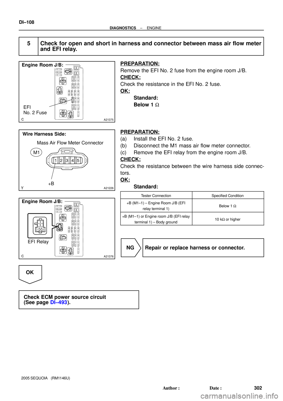
A21375
Engine Room J/B:
EFI
No. 2 Fuse
A21226
Wire Harness Side:
Mass Air Flow Meter Connector
M1
+B
A21376
Engine Room J/B:
EFI Relay
DI±108
± DIAGNOSTICSENGINE
302 Author�: Date�:
2005 SEQUOIA (RM1146U)
5 Check for open and short in harness and connector between mass air flow meter
and EFI relay.
PREPARATION:
Remove the EFI No. 2 fuse from the engine room J/B.
CHECK:
Check the resistance in the EFI No. 2 fuse.
OK:
Standard:
Below 1 W
PREPARATION:
(a) Install the EFI No. 2 fuse.
(b) Disconnect the M1 mass air flow meter connector.
(c) Remove the EFI relay from the engine room J/B.
CHECK:
Check the resistance between the wire harness side connec-
tors.
OK:
Standard:
Tester ConnectionSpecified Condition
+B (M1±1) ± Engine Room J/B (EFI
relay terminal 1)Below 1 W
+B (M1±1) or Engine room J/B (EFI relay
terminal 1) ± Body ground10 kW or higher
NG Repair or replace harness or connector.
OK
Check ECM power source circuit
(See page DI±493).
Page 501 of 4323
A23548
ECM
E4
STAR ACCR
AM28
ED I18
Ignition SWB B
B±W 1C9
620
42 P
1
B±W
B 1
J2
J/C 1
17
B±O
2D
ALTE7 J38
1FGR
W4
ED2 IA1
S3 F10
Fusible
Link Block4
W±R
B±L
Battery 5B
ST 3A
1
StarterST Relay 5
B
12 3
Instrument Panel J/B
12
Engine Room J/B
2C
5 Sub J/B No. 4
P 3A 12A36
ACC CUT Relay
to Audio
J37J/C
C
GR
4 GR
N B±R
B±R
J/C BD
J51 J52B±R
STSW
E6 IG4B
Engine Room R/B No.2
2 B
2 2
2
2 2 B±RB±R RAD No.2
1C
1C
1C
1J 1J1J
1L
1E 3
5
W±L W±R
W±R
2C
2E1
3B±R
3
B1
B±W
W±B 6
A 1
2 3 58
3
J5
J/C 1
1W±B 128 B±R
W±RJ51 BE6 11
STA W±R
21
3
S2W±R4A
4B 19
9 Sub J/B No.4 GR
P1
Park/Neutral
Position SW
AM1ACC
AM2
ST2
ECU±B
SHORT PIN
B 7
B 2AM1
1
STA8
IA5
± DIAGNOSTICSENGINE
DI±299
493 Author�: Date�:
2005 SEQUOIA (RM1146U)
WIRING DIAGRAM
Page 695 of 4323
± DIAGNOSTICSENGINE
DI±493
687 Author�: Date�:
2005 SEQUOIA (RM1146U)
ECM Power Source Circuit
CIRCUIT DESCRIPTION
When the ignition switch is turned ON, battery positive voltage is applied to terminal IGSW of the ECM and
the EFI relay control circuit in the ECM sends a signal to terminal MREL of the ECM switching on the EFI
relay.
This signal causes current to flow to the coil, closing the contacts of the EFI relay and supplying power to
terminal +B of the ECM.
DID8K±01
Page 1501 of 4323
± DIAGNOSTICSSUPPLEMENTAL RESTRAINT SYSTEM
DI±1299
1493 Author�: Date�:
2005 SEQUOIA (RM1146U)
12 Replace front seat assembly RH.
(a) Turn the ignition switch to the LOCK position.
(b) Disconnect the negative (±) terminal cable from the battery, and wait for at least 90 seconds.
(c) Replace the front seat assembly RH (see page BO±112, BO±126).
NEXT
13 Perform zero point calibration.
(a) Connect the negative (±) terminal cable to the battery.
(b) Connect the hand±held tester to the DLC3.
(c) Turn the ignition switch to the ON position.
(d) Using the hand±held tester, perform ºZero point calibrationº (see page DI±1128).
OK:
The ºCOMPLETEDº is displayed.
NEXT
14 Perform sensitivity check.
Using the hand±held tester, perform ºSensitivity checkº (see page DI±1128).
OK:
Standard value: 27 to 33 kg (59.52 to 72.75 lb)
NEXT
END
Page 1695 of 4323

INSPECTION PROCEDURE
1 Check battery.
CHECK:
Measure the voltage of the battery.
OK:
Voltage: 11 to 1")
± DIAGNOSTICSSUPPLEMENTAL RESTRAINT SYSTEM
DI±1493
1687 Author�: Date�:
2005 SEQUOIA (RM1146U)
INSPECTION PROCEDURE
1 Check battery.
CHECK:
Measure the voltage of the battery.
OK:
Voltage: 11 to 14 V
NG Replace battery.
OK
2 Check connection of connectors.
PREPARATION:
Disconnect the negative (±) terminal cable from the battery, and wait for at least 90 seconds.
CHECK:
Check that the connectors are properly connected to the airbag sensor assembly and combination meter.
OK:
The connectors are connected securely.
NG Connect connectors.
OK
3 Prepare for inspection.
CAUTION:
Be sure to perform the following procedures before troubleshooting to avoid unexpected airbag de-
ployment.
(a) Disconnect the connectors from the airbag sensor assembly.
(b) Disconnect the connectors from the steering wheel pad.
(c) Disconnect the connectors from the front passenger airbag assembly.
(d) w/ Side and curtain shield airbag:
Disconnect the connectors from the side airbag assembly LH and RH.
(e) w/ Side and curtain shield airbag:
Disconnect the connectors from the curtain shield airbag assembly LH and RH.
(f) Disconnect the connectors from the front seat outer belt LH and RH.
NEXT