Page 3090 of 4323
SA244±06
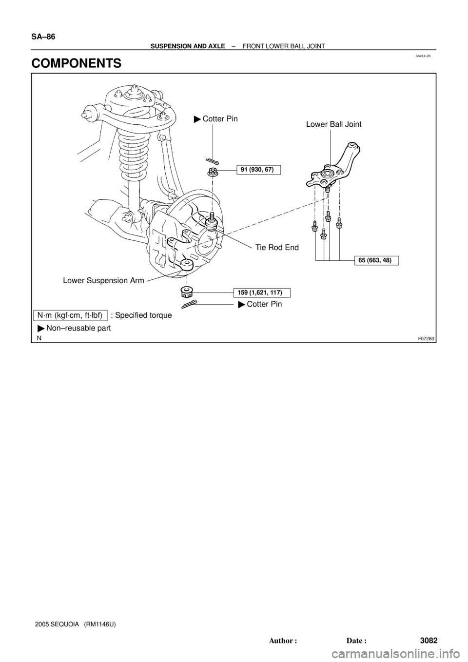
F07280
N´m (kgf´cm, ft´lbf) : Specified torque
� Non±reusable part
Tie Rod End
� Cotter Pin Lower Suspension ArmLower Ball Joint � Cotter Pin
91 (930, 67)
65 (663, 48)
159 (1,621, 117)
SA±86
± SUSPENSION AND AXLEFRONT LOWER BALL JOINT
3082 Author�: Date�:
2005 SEQUOIA (RM1146U)
COMPONENTS
Page 3091 of 4323
SA245±05
R13300
R13425
SST
R12863
SST
± SUSPENSION AND AXLEFRONT LOWER BALL JOINT
SA±87
3083 Author�: Date�:
2005 SEQUOIA (RM1146U)
REMOVAL
1. REMOVE FRONT WHEEL
2. LOOSEN 4 LOWER BALL JOINT SET BOLTS
HINT:
Do not remove the bolts.
3. DISCONNECT TIE ROD END
(a) Remove the cotter pin and nut from the tie rod end.
(b) Using SST, disconnect the tie rod end from the lower ball
joint.
SST 09610±20012
4. REMOVE LOWER BALL JOINT
(a) Remove the cotter pin and nut from the lower ball joint.
(b) Using SST, disconnect the lower ball joint from the lower
suspension arm.
SST 09628±62011
(c) Remove the 4 lower ball joint set bolts.
(d) While lifting the upper suspension arm and steering
knuckle, remove the lower ball joint.
(e) Support the upper suspension arm and steering knuckle
securely.
Page 3093 of 4323

INSTALLATION
1. INSTALL LOWER BALL JOINT
(a) While lifting the upper suspension arm and stee")
SA247±07
± SUSPENSION AND AXLEFRONT LOWER BALL JOINT
SA±89
3085 Author�: Date�:
2005 SEQUOIA (RM1146U)
INSTALLATION
1. INSTALL LOWER BALL JOINT
(a) While lifting the upper suspension arm and steering knuckle, install the lower ball joint.
(b) Temporarily install the 4 bolts to the lower ball joint.
(c) Install the set nut to hold the lower ball joint to the lower suspension arm and a new cotter pin.
Torque: 159 N´m (1,621 kgf´cm, 117 ft´lbf)
If the holes for the cotter pin are not aligned, tighten the nut further up to 60°.
2. CONNECT TIE ROD END
Connect the tie rod end to the lower ball joint with the nut and a new cotter pin.
Torque: 91 N´m (930 kgf´cm, 67 ft´lbf)
If the holes for the cotter pin are not aligned, tighten the nut further up to 60°.
3. TIGHTEN LOWER BALL JOINT SET 4 BOLTS
Torque: 65 N´m (663 kgf´cm, 48 ft´lbf)
4. INSTALL FRONT WHEEL
Torque: 110 N´m (1,150 kgf´cm, 83 ft´lbf)
5. CHECK FRONT WHEEL ALIGNMENT (See page SA±4)
6. PERFORM ZERO POINT CALIBRATION OF STEERING ANGLE, MASTER CYLINDER PRES-
SURE, YAW RATE AND DECELERATION SENSORS (See page DI±897)
Page 3108 of 4323
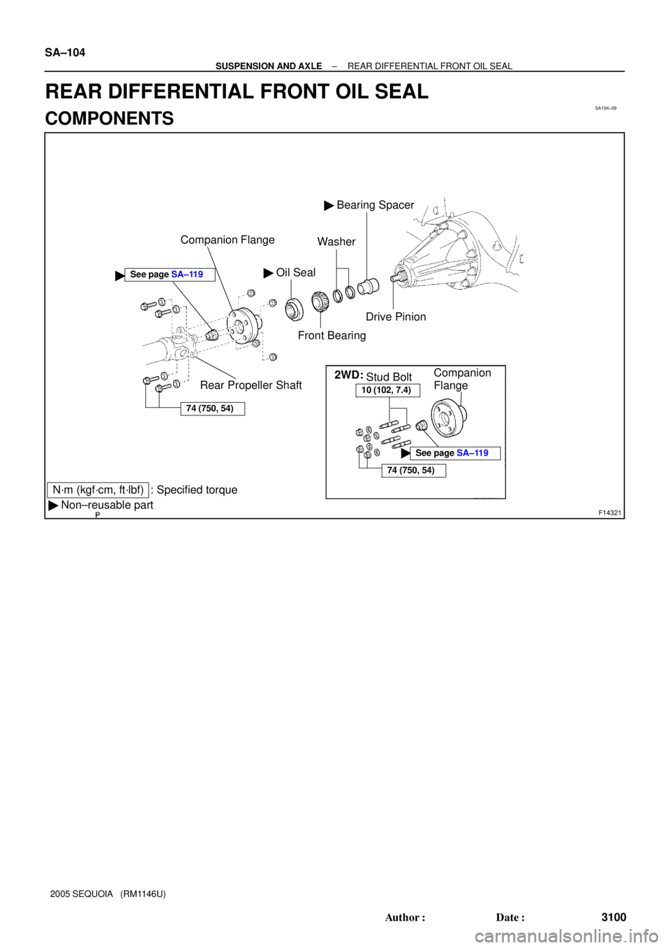
SA15K±09
F14321
� Oil Seal
Front Bearing
� Bearing Spacer
N´m (kgf´cm, ft´lbf) : Specified torque
� Non±reusable partCompanion Flange
Rear Propeller ShaftWasher
�
74 (750, 54)
Drive Pinion
2WD:
10 (102, 7.4)
74 (750, 54)
�See page SA±119
Stud BoltCompanion
Flange
See page SA±119
SA±104
± SUSPENSION AND AXLEREAR DIFFERENTIAL FRONT OIL SEAL
3100 Author�: Date�:
2005 SEQUOIA (RM1146U)
REAR DIFFERENTIAL FRONT OIL SEAL
COMPONENTS
Page 3110 of 4323
SA2349
SST
R13357
SST
R13358
SST SST
R13359
SST SA±106
± SUSPENSION AND AXLEREAR DIFFERENTIAL FRONT OIL SEAL
3102 Author�: Date�:
2005 SEQUOIA (RM1146U)
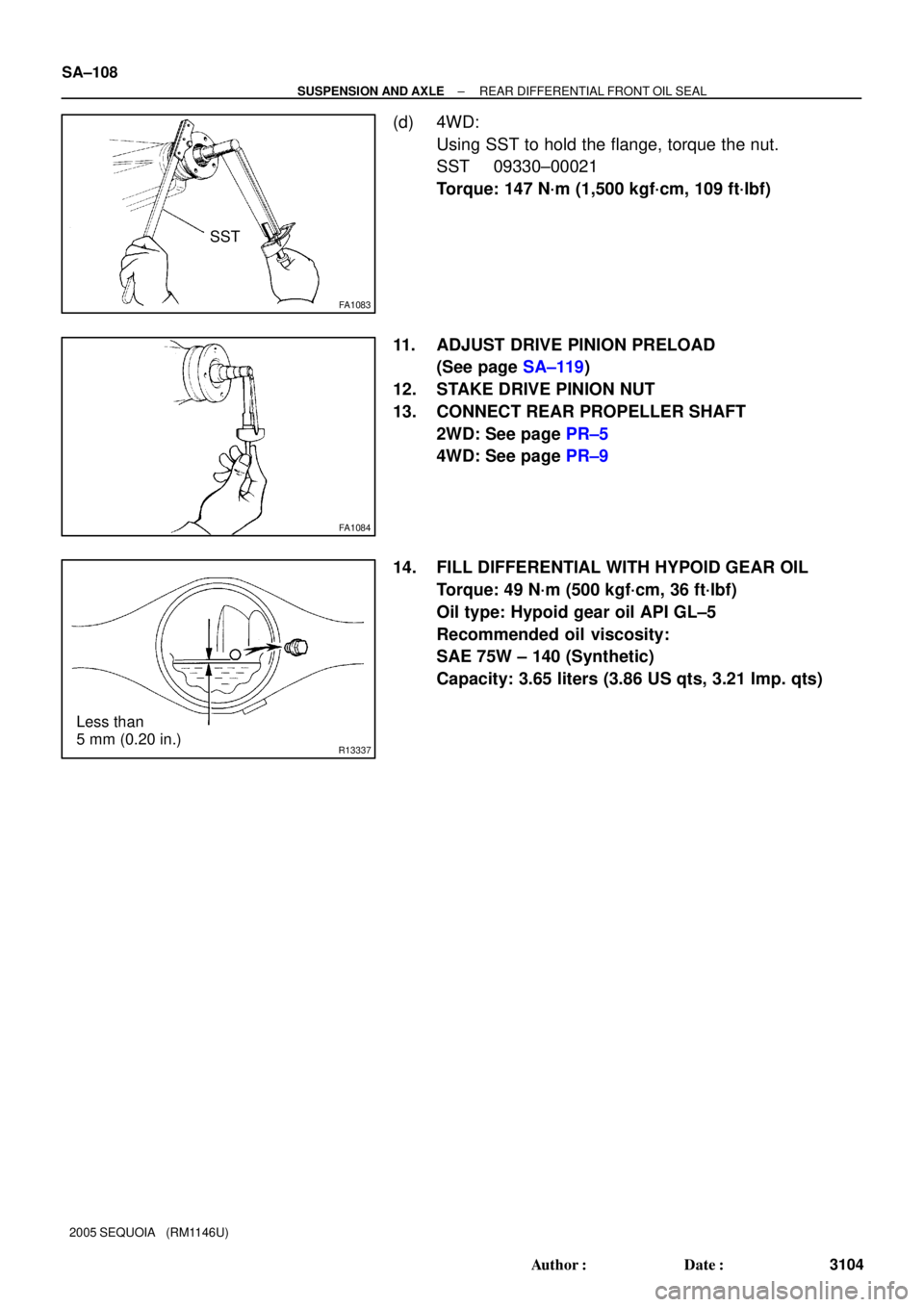
(b) 4WD:
(1) Using a chisel and hammer, loosen the staked part
of the nut.
(2) Using SST to hold the flange, remove the nut.
SST 09330±00021
(c) Using SST, remove the companion flange.
SST 09950±30012 (09951±03010, 09953±03010,
09954±03010, 09955±03030, 09956±03050)
4. REMOVE OIL SEAL
Using SST, remove the oil seal.
SST 09308±10010
5. REMOVE FRONT BEARING
Using SST, remove the front bearing from the drive pinion.
SST 09556±22010
6. REMOVE BEARING SPACER
(a) Remove the 2 washers.
(b) Remove the bearing spacer.
7. INSTALL NEW BEARING SPACER
(a) Install a new bearing spacer.
(b) Install the 2 washers.
8. INSTALL FRONT BEARING
(a) Place the front bearing.
Page 3111 of 4323

F14485
SST
F14522SST
± SUSPENSION AND AXLEREAR DIFFERENTIAL FRONT OIL SEAL
SA±107
3103 Author�: Date�:
2005 SEQUOIA (RM1146U)
(b) Using SST")
R13361
SST
R13360
SST
Vinyl Tape
F14486
40 mm
(1.57 in.)
F14485
SST
F14522SST
± SUSPENSION AND AXLEREAR DIFFERENTIAL FRONT OIL SEAL
SA±107
3103 Author�: Date�:
2005 SEQUOIA (RM1146U)
(b) Using SST and the companion flange, install the front
bearing then remove the companion flange.
SST 09950±30012 (09951±03010, 09953±03010,
09954±03010, 09955±03030, 09956±03050)
9. INSTALL NEW OIL SEAL
(a) Coat a new oil seal lip with MP grease.
(b) Using SST and a plastic hammer, install the oil seal until
its surface is flush with the differential carrier end.
SST 09316±12010, 09649±17010
HINT:
Connect 2 SST with vinyl tape.
10. INSTALL COMPANION FLANGE
(a) Place the companion flange on the drive pinion.
(b) Coat the threads of a new nut with hypoid gear oil.
(c) 2WD:
Install the companion flange nut.
(1) Install the 3 stud bolts so that the heads come out
40 mm (1.57 in.).
(2) Set the SST and install the 3 nuts to the companion
flange .
SST 09213±58013
(3) Install the other SST to the set SST to hold the com-
panion flange and torque the nut.
SST 09330±00021
Torque: 147 N´m (1,500 kgf´cm, 109 ft´lbf)
(4) Remove the 3 nuts, SST and stud bolts from the
companion flange.
Page 3112 of 4323
FA1083
SST
FA1084
R13337
Less than
5 mm (0.20 in.) SA±108
± SUSPENSION AND AXLEREAR DIFFERENTIAL FRONT OIL SEAL
3104 Author�: Date�:
2005 SEQUOIA (RM1146U)
(d) 4WD:
Using SST to hold the flange, torque the nut.
SST 09330±00021
Torque: 147 N´m (1,500 kgf´cm, 109 ft´lbf)
11. ADJUST DRIVE PINION PRELOAD
(See page SA±119)
12. STAKE DRIVE PINION NUT
13. CONNECT REAR PROPELLER SHAFT
2WD: See page PR±5
4WD: See page PR±9
14. FILL DIFFERENTIAL WITH HYPOID GEAR OIL
Torque: 49 N´m (500 kgf´cm, 36 ft´lbf)
Oil type: Hypoid gear oil API GL±5
Recommended oil viscosity:
SAE 75W ± 140 (Synthetic)
Capacity: 3.65 liters (3.86 US qts, 3.21 Imp. qts)
Page 3114 of 4323
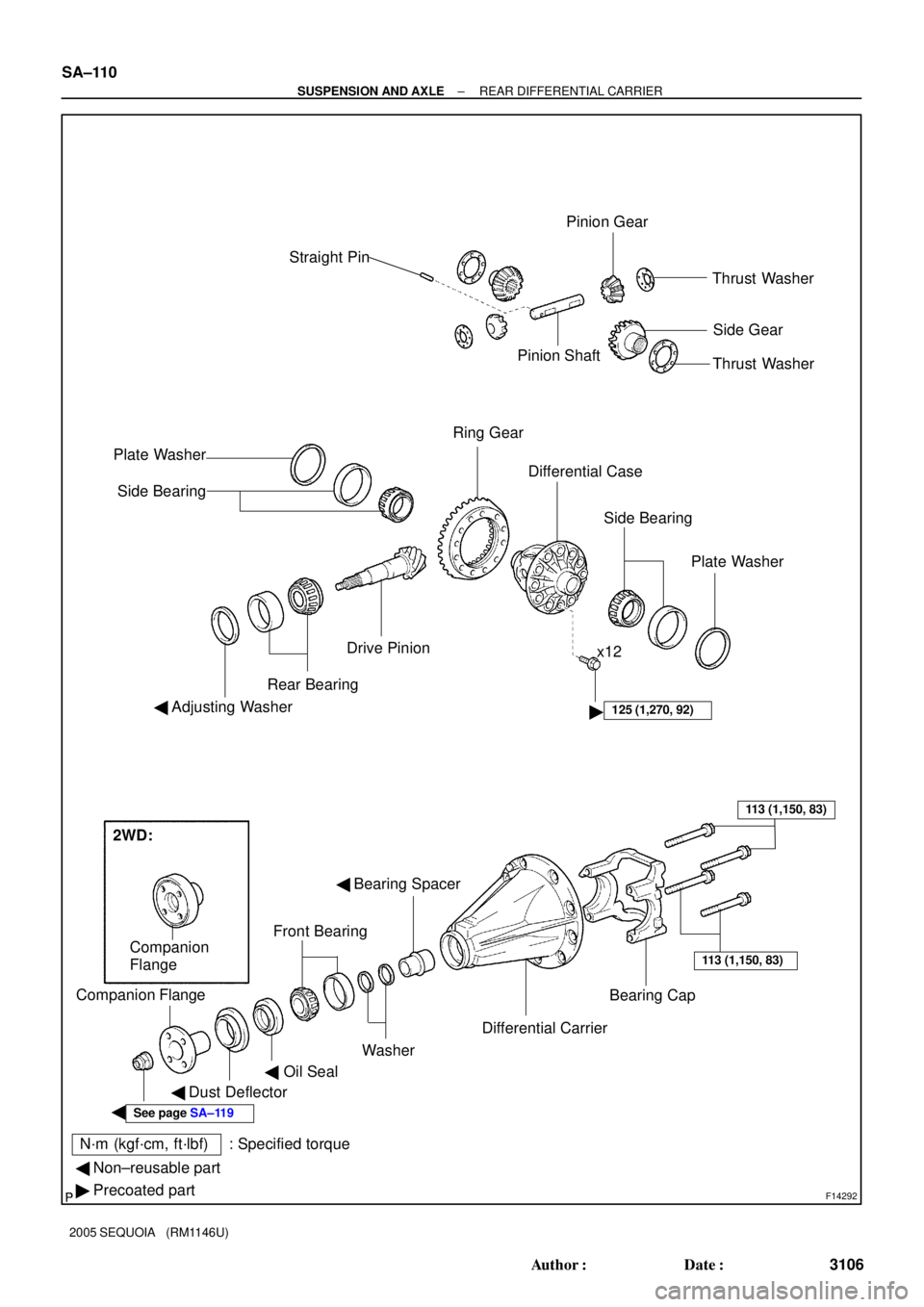
F14292
N´m (kgf´cm, ft´lbf) : Specified torqueStraight Pin
Pinion ShaftPinion Gear
Thrust Washer
Side Gear
Ring Gear
� Differential Case
Drive Pinion
Rear Bearing
� Adjusting Washer
� Bearing Spacer
Front Bearing
� Dust Deflector Companion Flange
Bearing CapThrust Washer
Plate Washer
Side Bearing
Side Bearing
Plate Washer
Differential Carrier
Washer
��Oil Seal
x12
125 (1,270, 92)
113 (1,150, 83)
113 (1,150, 83)
See page SA±119
� Non±reusable part
� Precoated part
Companion
Flange
2WD: SA±110
± SUSPENSION AND AXLEREAR DIFFERENTIAL CARRIER
3106 Author�: Date�:
2005 SEQUOIA (RM1146U)