Page 162 of 4323
SS0PK±05
SS±20
± SERVICE SPECIFICATIONSSTARTING
162 Author�: Date�:
2005 SEQUOIA (RM1146U)
STARTING
SERVICE DATA
StarterRated voltage and output power
No±load characteristics Current
rpm
Brush length
STD
Minimum
Spring installed load
STD
Minimum
Commutator
Diameter STD
Minimum
Undercut depth STD
Minimum
Circle runout Maximum
Field frame
Shunt coil resistance at 20°C (68°F)
Magnetic switch
Contact plate for wear Maximum12 V
100 A or less at 11.5 V
2,500 rpm or less
15.0 mm (0.591 in.)
9.0 mm (0.354 in.)
21.5 to 27.5 N (2.2 to 2.8 kgf, 4.8 to 6.2 lbf)
12.7 N (1.3 kgf, 2.9 lbf)
35.0 mm (1.378 in.)
34.0 mm (1.339 in.)
0.7 mm (0.028 in.)
0.2 mm (0.008 in.)
0.05 mm (0.0020 in.)
1.5 to 1.9 W
0.9 mm (0.035 in.)
Page 902 of 4323

DIDCN±01
F19465
: CAN
Compressor Assy
Combination Meter
Suspension
Control
ECU Exhaust Solenoid
Valve
Gate Solenoid Valve
Leveling Solenoid ValveAIR SUS Relay
Height Control Cylinder
(Pneumatic Cylinder)
Height Control Sensor
Sub±assy : ECU Output Signal
: ECU Input Signal
: Air Flow Path
Dryer
Height Control Cylinder
(Pneumatic Cylinder)� Speed Sensors
� Engine Speed
� L4 Switch
� Shift Position
Information
� Transmission
Model Informa-
tion
� Height Control Mode Select
Switch
� Height Control Switch
� Courtesy Light Switches
� Stop Light SwitchHI
N
LO
MAN. DI±700
± DIAGNOSTICSAIR SUSPENSION SYSTEM
894 Author�: Date�:
2005 SEQUOIA (RM1146U)
SYSTEM DESCRIPTION
1. GENERAL
�This system uses pneumatic cylinders instead of the coil springs that are used in a conventional rear
suspension. The suspension control ECU analyzes the information based on the switches, sensors,
and input signals, operates the compressor assy, and uses the solenoid valves to control the vehicle
height.
�The suspension control ECU detects, via the height control sensor, the changes in the rear vehicle
height that results from the number of occupants or the amount of the load. Then, the suspension con-
trol ECU controls the height control solenoid valves and the compressor assy in order to automatically
adjust the rear vehicle height to a constant (normal) vehicle height.
�Furthermore, three vehicle heights can be selected by operating the height control switch: HI, NOR-
MAL, and LO. The HI vehicle height ensures the vehicle's drive±through performance on rough roads.
The LO vehicle height facilitates the entry and exit of the occupants and the loading and unloading
of cargo. The NORMAL vehicle height helps realize excellent controllability and riding comfort during
normal driving.
Page 2886 of 4323
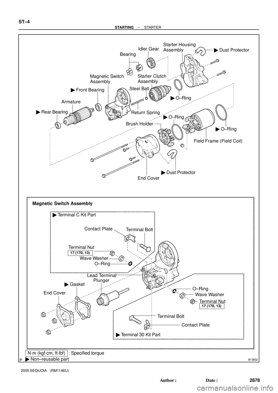
B13802
� O±Ring Idler GearStarter Housing
Assembly
Return SpringStarter Clutch
Assembly
Steel Ball
Contact Plate � Rear BearingArmatureMagnetic Switch
AssemblyBearing
� Front Bearing
� O±Ring
End Cover
Brush Holder
Magnetic Switch Assembly
Terminal Nut
O±Ring Wave WasherTerminal Bolt
� Terminal C Kit Part
Lead Terminal
Plunger
� Gasket
End Cover
Terminal BoltWave Washer O±Ring
Terminal Nut
� Terminal 30 Kit Part
� Non±reusable part
� Dust Protector
� Dust Protector
Field Frame (Field Coil)
17 (170, 13)
17 (170, 13)
N´m (kgf´cm, ft´lbf) : Specified torque� O±Ring
Contact Plate
ST±4
± STARTINGSTARTER
2878 Author�: Date�:
2005 SEQUOIA (RM1146U)
Page 2891 of 4323

(A)
Z00037
ST0019
± STARTINGSTARTER
ST±9
2883 Author�: Date�:
2005 SEQUOIA (RM1146U)
7. INSPECT FIELD COIL FOR OPEN CIRCUIT")
P10588
Ohmmeter
Continuity
P00299
OhmmeterContinuity
S02267
Ohmmeter(B)
(A)
Z00037
ST0019
± STARTINGSTARTER
ST±9
2883 Author�: Date�:
2005 SEQUOIA (RM1146U)
7. INSPECT FIELD COIL FOR OPEN CIRCUIT
Using an ohmmeter, check that there is continuity between the
lead wire and field coil brush lead.
If there is no continuity, replace the field frame.
8. INSPECT SHUNT COIL FOR OPEN CIRCUIT
Using an ohmmeter, check that there is continuity between the
field coil end and field frame.
If there is no continuity, repair or replace the field frame.
9. INSPECT SHUNT COIL FOR OPEN CIRCUIT
Using an ohmmeter, measure the resistance between shunt
coil terminals (A) and (B).
Resistance: 1.5 to 1.9 W at 20 °C (68 °F)
If the resistance is not as specified, replace the field frame.
10. INSPECT BRUSH LENGTH
Using vernier calipers, measure the brush length.
Standard length: 15.0 mm (0.591 in. )
Minimum length: 9.0 mm (0.354 in. )
If the length is less than minimum, replace the brush holder and
field frame.
11. INSPECT BRUSH SPRING LOAD
Using a pull scale, measure the spring load by pulling the spring
from the brush until they are separated.
Standard spring installed load: 21.5 to 27.5 N ( 2.2 to
2.8 kgf, 4.8 to 6.2 lbf )
Minimum installed load: 12.7 N (1.3 kgf, 2.9 lbf )
If the installed load is less than minimum, replace the brush
springs.
Page 3034 of 4323
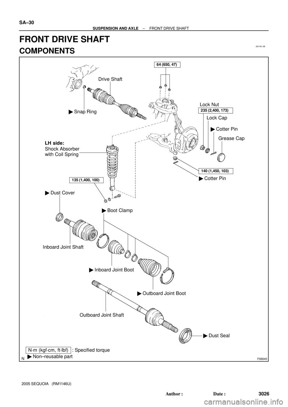
SA14E±08
F06645
� Snap Ring
Drive Shaft
� Dust Cover
Inboard Joint Shaft
� Inboard Joint Boot
� Outboard Joint Boot
� Boot Clamp
� Dust Seal Outboard Joint Shaft
� Cotter Pin� Cotter Pin
Grease Cap Lock Cap Lock Nut
235 (2,400, 173)
140 (1,450, 103)
� Non±reusable part
N´m (kgf´cm, ft´lbf) : Specified torqueShock Absorber
with Coil Spring
135 (1,400, 100)
LH side:
64 (650, 47)
SA±30
± SUSPENSION AND AXLEFRONT DRIVE SHAFT
3026 Author�: Date�:
2005 SEQUOIA (RM1146U)
FRONT DRIVE SHAFT
COMPONENTS
Page 3067 of 4323
SA17Y±06
F14311
Shock Absorber
with Coil Spring
N´m (kgf´cm, ft´lbf)
: Specified torque
64 (650, 47)
Retainer
Cushion
Suspension
Support
Retainer
Coil Spring
Shock Absorber
25 (250, 18)
135 (1,400, 100)
Bushing�
± SUSPENSION AND AXLEFRONT SHOCK ABSORBER
SA±63
3059 Author�: Date�:
2005 SEQUOIA (RM1146U)
FRONT SHOCK ABSORBER
COMPONENTS
Page 3068 of 4323
SA23R±03
F14315
R12773
SA±64
± SUSPENSION AND AXLEFRONT SHOCK ABSORBER
3060 Author�: Date�:
2005 SEQUOIA (RM1146U)
REMOVAL
1. REMOVE FRONT WHEEL
2. DISCONNECT SHOCK ABSORBER FROM LOWER
SUSPENSION ARM
(a) Remove the shock absorber lower side set nut and wash-
er.
NOTICE:
Do not remove the bolt.
(b) Pry down the lower suspension arm to remove the bolt
and disconnect the shock absorber.
3. REMOVE SHOCK ABSORBER WITH COIL SPRING
Remove the 3 nuts and shock absorber with the coil spring.
Page 3069 of 4323
SA23S±03
F14523
± SUSPENSION AND AXLEFRONT SHOCK ABSORBER
SA±65
3061 Author�: Date�:
2005 SEQUOIA (RM1146U)
DISASSEMBLY
REMOVE SUSPENSION SUPPORT AND COIL SPRING
(a) Using a spring compressor, compress the coil spring.
NOTICE:
�Use a spring compressor with which compressive
force of 12,740 N (1,300 kgf, 2,860 lbf) or more can be
applied.
�Make sure that the suspension support is free from
the coil spring.
�Do not compress the coil spring more than neces-
sary.
�Do not place yourself over the top of the shock ab-
sorber.
(b) Remove the suspension support center nut.
(c) Remove the 2 retainers, cushion, suspension support
and coil spring.


: Specified torque
64 (650, 47)
Retainer
Cushion
Suspension
Support
Retainer
Coil Spring
Shock Absorber
25 (250, 18)
135 (1,400")