Page 3376 of 4323

RS0BO±11
H23231
± SUPPLEMENTAL RESTRAINT SYSTEMAIRBAG SENSOR ASSEMBLY
RS±85
3368 Author�: Date�:
2005 SEQUOIA (RM1146U)
INSTALLATION
NOTICE:
�Never use SRS parts from another vehicle. When re-
placing parts, replace them with new ones.
�Never reuse the airbag sensor assembly involved in
a collision when the airbag has deployed.
�If the airbag sensor assembly center has been
dropped, or there are any cracks, dents or other de-
fects in the case, bracket or connector, replace it with
a new one.
�When installing the airbag sensor assembly center,
be careful that the SRS wiring does not interfere with
other parts and that it is not pinched between other
parts.
�After installing, shake the airbag sensor assembly to
check that there is no looseness.
1. INSTALL AIRBAG SENSOR ASSEMBLY
(a) Install the airbag sensor assembly with the 4 bolts.
Torque: 17.5 N´m (179 kgf´cm, 13 ft´lbf)
(b) Connect the airbag sensor holder (with connectors).
2. INSTALL FRONT CONSOLE BOX ASSEMBLY
(SEE PAGE BO±89)
3. INSTALL REAR CONSOLE BOX ASSEMBLY
(SEE PAGE BO±89)
4. INSTALL UPPER CONSOLE PANEL
(SEE PAGE BO±89)
5. INSTALL SHIFTING HOLE COVER
(SEE PAGE BO±89)
6. CONNECT CABLE TO NEGATIVE BATTERY TERMI-
NAL
7. PERFORM INITIALIZATION (SEE PAGE BE±77)
Some system need initialization when disconnecting the cable
from the negative battery terminal.
8. INSPECT SRS WARNING LIGHT (SEE PAGE DI±1137)
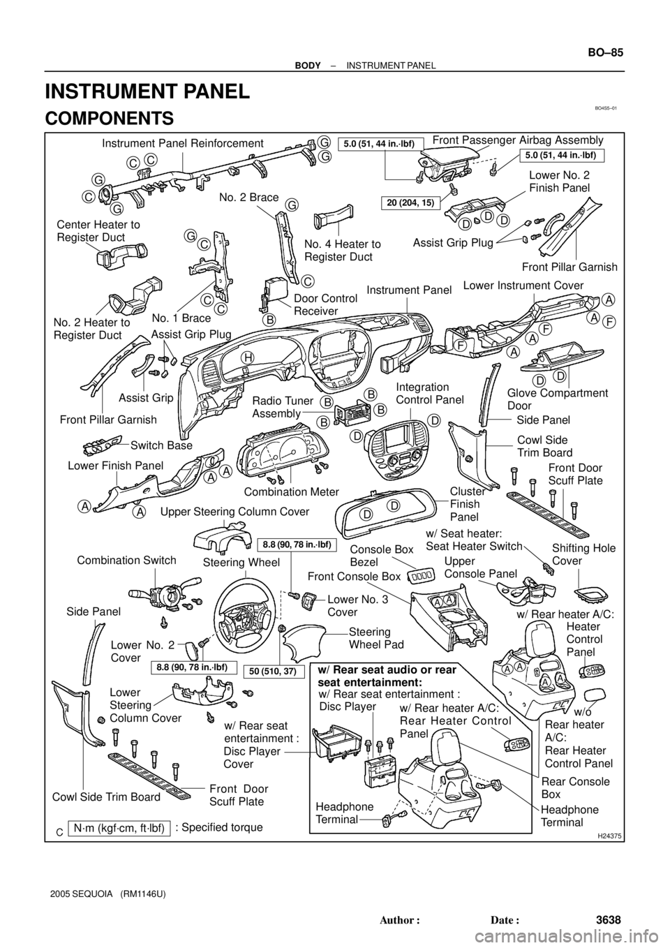
Page 3646 of 4323

BO4S5±01
H24375
Instrument Panel ReinforcementFront Passenger Airbag Assembly
Lower No. 2
Finish Panel
No. 2 Brace
Center Heater to
Register Duct
No. 1 Brace
No. 2 Heater to
Register DuctNo. 4 Heater to
Register DuctAssist Grip Plug
Instrument Panel
Radio Tuner
Assembly Assist Grip
Front Pillar Garnish
Combination Meter Switch Base
Lower Finish PanelGlove Compartment
Door
Side Panel
Cowl Side
Trim Board
Cluster
Finish
Panel
Console Box
BezelUpper
Console Panel w/ Seat heater:
Seat Heater Switch
Steering
Wheel Pad Front Console Box
Lower
Steering
Column Cover
Front Door
Scuff Plate
N´m (kgf´cm, ft´lbf): Specified torque
CC
G
G
C
G
G
G
GC
CC
C
DDD
DD
A
A
A
A
AA
AA
F
FF
DD
D
DB
BB
B
5.0 (51, 44 in.´lbf)
20 (204, 15)
A
A
Headphone
Terminal
8.8 (90, 78 in.´lbf)
Lower No. 2
CoverLower No. 3
Cover
AAAA
Headphone
TerminalRear Console
Box w/ Rear seat entertainment :
w/ Rear heater A/C:
Rear Heater Control
Panel
w/ Rear seat
entertainment :
Disc Player
Coverw/ Rear heater A/C:
Disc Player
w/o
Rear heater
A/C:
Rear Heater
Control PanelHeater
Control
Panel
w/ Rear seat audio or rear
seat entertainment:
8.8 (90, 78 in.´lbf)
Steering Wheel
Upper Steering Column Cover
Front Door
Scuff Plate
Side Panel
Cowl Side Trim Board
5.0 (51, 44 in.´lbf)
Integration
Control Panel
Combination Switch
50 (510, 37)
Front Pillar Garnish
Lower Instrument Cover
Shifting Hole
Cover
Door Control
Receiver
Assist Grip Plug
H
B
± BODYINSTRUMENT PANEL
BO±85
3638 Author�: Date�:
2005 SEQUOIA (RM1146U)
INSTRUMENT PANEL
COMPONENTS
Page 3655 of 4323
H11182
BO±94
± BODYINSTRUMENT PANEL
3647 Author�: Date�:
2005 SEQUOIA (RM1146U)
31. REMOVE CENTER HEATER TO REGISTER DUCT
32. REMOVE INSTRUMENT PANEL REINFORCEMENT
(a) Disconnect the connectors.
(b) Remove the bolt and door control receiver.
(c) Remove the 3 bolts, nut and No. 1 brace.
(d) Remove the bolt, nut and No. 2 brace.
(e) Remove the 3 bolts, 4 nuts and instrument panel rein-
forcement.
33. REMOVE CONSOLE COMPARTMENT BOX AS-
SEMBLY
34. REMOVE BOX PANEL SUB±ASSEMBLY
Remove the 3 bolts and box panel sub±assembly.
Torque: 40 N´m (408 kgf´cm, 30 ft´lbf)
Page 3861 of 4323
05_SEQUOIA_U (L/O 0408)
2
2005 SEQUOIA from Aug. '04 Prod. (OM34424U)
1. Side vents
2. Instrument cluster
3. Center vents
4. Multi±information display
5. Personal lights
6. Garage door opener box or auxiliary
box
7. Electric moon roof switches
8. Side defroster outlet
9. Glove box
10. Power door lock switches
11. Power window switches
12. Power outlets
13. Seat heater switches
14. Rear console box
15. Rear air conditioning controls
16. Headphone input jacks and headphone
volume control dials
17. Input terminal adapter
18. Cup holders
19. Power rear view mirror control switches
20. Lower vent
Instrument panel overview
�View A