Page 3142 of 4323

(c) While holding the piston rod, remove the nut, retainer,")
F16919
F16920
F14307
F04396
SA±138
± SUSPENSION AND AXLECOIL SPRING AND REAR SHOCK ABSORBER
3134 Author�: Date�:
2005 SEQUOIA (RM1146U)
(c) While holding the piston rod, remove the nut, retainer,
cushion and shock absorber.
Torque: 58 N´m (591 kgf´cm, 43 ft´lbf)
(d) Remove the retainer and cushion from the shock absorb-
er.
5. DISCONNECT LH AND RH STABILIZER BAR LINKS
Remove the 2 nuts and disconnect the LH and RH stabilizer bar
links.
Torque: 69 N´m (704 kgf´cm, 51 ft´lbf)
6. DISCONNECT LATERAL CONTROL ROD
Remove the nut, washer, bolt and disconnect the lateral control
rod.
Torque: 140 N´m (1,428 kgf´cm, 103 ft´lbf)
HINT:
At the time of installation, after stabilizing the suspension,
torque the nut and bolt.
7. REMOVE COIL SPRING
(a) Lower the axle housing.
NOTICE:
Be careful not to snap the brake line and parking brake
cable.
(b) While lowering the axle housing, remove the coil spring,
hollow spring and insulator.
HINT:
At the time of installation, please refer to the following items.
�Check that the coil spring end is installed correctly.
�If the coil spring end is not in the correct position, reinstall
the coil spring.
Page 3143 of 4323
SA174±05
SA0627
± SUSPENSION AND AXLECOIL SPRING AND REAR SHOCK ABSORBER
SA±139
3135 Author�: Date�:
2005 SEQUOIA (RM1146U)
INSPECTION
Normal Type:
INSPECT SHOCK ABSORBER
Compress and extend the shock absorber rod and check that
there is no abnormal resistance or unusual operation sounds.
If there is any abnormality, replace the shock absorber with a
new one.
Page 3144 of 4323
30 mm
(1.18 in.)
F17130
50 mm (1.97 in.) High Pressure
Chamber Side:130 mm (5.12 in.)
F17131
Low Pressure
Chamber Side:50 mm (1.97 in.)
40 mm (1.57 in.) SA±140")
SA2BI±02
W03120F07370
50 mm
(1.97 in.)30 mm
(1.18 in.)
F17130
50 mm (1.97 in.) High Pressure
Chamber Side:130 mm (5.12 in.)
F17131
Low Pressure
Chamber Side:50 mm (1.97 in.)
40 mm (1.57 in.) SA±140
± SUSPENSION AND AXLECOIL SPRING AND REAR SHOCK ABSORBER
3136 Author�: Date�:
2005 SEQUOIA (RM1146U)
DISPOSAL
1. FULLY EXTEND SHOCK ABSORBER ROD
2. Normal Type:
DRILL HOLE TO REMOVE GAS FROM CYLINDER
Using a drill, make a hole in the cylinder, as shown in the illustra-
tion to discharge the gas inside.
CAUTION:
The discharged gas is harmless, but be careful of chips
which may fly out when drilling.
3. Auto Leveler Type:
DRILL HOLE TO REMOVE GAS FROM CYLINDER
Using a drill, make a hole on the shaded area of the cylinder,
as shown in the illustration to discharge the gas inside.
CAUTION:
�Be sure to perform the procedure in the order, the
high pressure chamber and the low pressure cham-
ber.
�Wear protective goggles and cover the absorber with
a plastic bag or like when boring.
�The discharged gas is harmless, but be careful of
chips which may fly out when drilling.
Page 3145 of 4323
SA175±05
F05063
SST
SST
F14312
SST
SST
± SUSPENSION AND AXLECOIL SPRING AND REAR SHOCK ABSORBER
SA±141
3137 Author�: Date�:
2005 SEQUOIA (RM1146U)
REPLACEMENT
1. Normal Type:
REMOVE BUSHING
Using SST and a press, remove the bushing.
SST 09710±14013 (09710±00061),
09710±28012 (09710±07031),
09950±70010 (09951±07100)
2. Normal Type:
INSTALL BUSHING
Using SST and a press, install a new bushing.
SST 09710±14013 (09710±00061),
09710±28012 (09710±07031),
09950±70010 (09951±07100)
Page 3146 of 4323
SA176±04
SA±142
± SUSPENSION AND AXLECOIL SPRING AND REAR SHOCK ABSORBER
3138 Author�: Date�:
2005 SEQUOIA (RM1146U)
INSTALLATION
Installation is in the reverse order of removal (See page SA±137).
Page 3248 of 4323
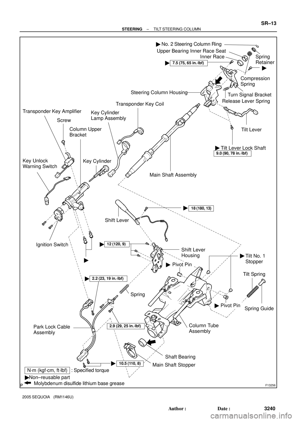
F13256
�Non±reusable part
Molybdenum disulfide lithium base grease
: Specified torqueN´m (kgf´cm, ft´lbf)Column Upper
Bracket
Key Cylinder Key Unlock
Warning Switch
Ignition Switch
10.5 (110, 8)�Column Tube
Assembly
2.2 (23, 19 in.´lbf)�
Spring Guide
�
Tilt Spring Main Shaft Assembly Steering Column Housing
Tilt Lever Release Lever SpringTurn Signal Bracket�
Compression
SpringSpring
Retainer Upper Bearing Inner Race Seat
Inner Race
�12 (120, 9)
Pivot Pin
Spring
Park Lock Cable
Assembly
Shaft Bearing
Main Shaft Stopper
Pivot Pin Shift Lever
Housing
18 (180, 13)�� �
Shift Lever
No. 2 Steering Column Ring�
Tilt Lever Lock Shaft9.0 (90, 78 in.´lbf)
�
��
7.5 (75, 65 in.´lbf)
2.9 (29, 25 in.´lbf)
Transponder Key Coil
Key Cylinder
Lamp Assembly
Screw
Transponder Key Amplifier
Tilt No. 1
Stopper
± STEERINGTILT STEERING COLUMN
SR±13
3240 Author�: Date�:
2005 SEQUOIA (RM1146U)
Page 3252 of 4323
SR0V1±06
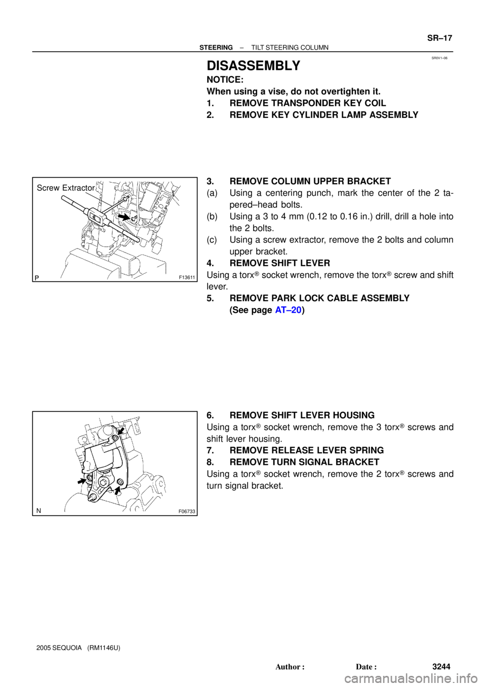
F13611
Screw Extractor
F06733
± STEERINGTILT STEERING COLUMN
SR±17
3244 Author�: Date�:
2005 SEQUOIA (RM1146U)
DISASSEMBLY
NOTICE:
When using a vise, do not overtighten it.
1. REMOVE TRANSPONDER KEY COIL
2. REMOVE KEY CYLINDER LAMP ASSEMBLY
3. REMOVE COLUMN UPPER BRACKET
(a) Using a centering punch, mark the center of the 2 ta-
pered±head bolts.
(b) Using a 3 to 4 mm (0.12 to 0.16 in.) drill, drill a hole into
the 2 bolts.
(c) Using a screw extractor, remove the 2 bolts and column
upper bracket.
4. REMOVE SHIFT LEVER
Using a torx® socket wrench, remove the torx® screw and shift
lever.
5. REMOVE PARK LOCK CABLE ASSEMBLY
(See page AT±20)
6. REMOVE SHIFT LEVER HOUSING
Using a torx® socket wrench, remove the 3 torx® screws and
shift lever housing.
7. REMOVE RELEASE LEVER SPRING
8. REMOVE TURN SIGNAL BRACKET
Using a torx® socket wrench, remove the 2 torx® screws and
turn signal bracket.
Page 3257 of 4323

7. INSTALL TURN SIGNAL BRACKET
Using a torx® socket wrench, install the turn signal bracket with
2 n")
F06737
F13612
SR±22
± STEERINGTILT STEERING COLUMN
3249 Author�: Date�:
2005 SEQUOIA (RM1146U)
7. INSTALL TURN SIGNAL BRACKET
Using a torx® socket wrench, install the turn signal bracket with
2 new torx® screws.
Torque: 7.5 N´m (75 kgf´cm, 65 in.´lbf)
HINT:
Make sure that the protrusion on the steering column housing
is fitted into the hole of the turn signal bracket.
8. INSTALL RELEASE LEVER SPRING
9. INSTALL SHIFT LEVER HOUSING
Using a torx® socket wrench, install the shift lever housing with
3 new torx® screws.
Torque: 12 N´m (120 kgf´cm, 9 ft´lbf)
10. INSTALL PARK LOCK CABLE ASSEMBLY (See page
AT±21)
11. INSTALL SHIFT LEVER
Using a torx® socket wrench, install the shift lever with a new
torx® screw.
Torque: 18 N´m (180 kgf´cm, 13 ft´lbf)
12. INSTALL COLUMN UPPER BRACKET
(a) Install the column upper bracket with 2 new tapered±
head bolts.
HINT:
Insert the bracket pin into the column tube hole.
(b) Tighten the tapered±head bolts until the bolt heads break
off.
13. INSTALL KEY CYLINDER LAMP ASSEMBLY
14. INSTALL TRANSPONDER KEY COIL
Page:
< prev 1-8 9-16 17-24