Page 281 of 4323
A02961
V5
VVT Sensor (Bank 1)ECM
1
2R
G
Y
LVVL+
VVL±
VVR+
E5 18
19
19
18
VVR±
1
2E5
E4
E4 V6
VVT Sensor (Bank 2)
± DIAGNOSTICSENGINE
DI±87
281 Author�: Date�:
2005 SEQUOIA (RM1146U)
WIRING DIAGRAM
INSPECTION PROCEDURE
HINT:
�If DTC P0016 is displayed, check left bank VVT sensor.
�If DTC P0018 is displayed, check right bank VVT sensor.
�Read freeze frame data using hand±held tester or OBD II scan tool. Because freeze frame records
the engine conditions when the malfunction is detected. When troubleshooting, it is useful for deter-
mining whether the vehicle was running or stopped, the engine was warmed up or not, the air±fuel ratio
was lean or rich, etc. at the time of the malfunction.
1 Check valve timing (Check for loose and jumping teeth of timing belt) (See page
EM±16).
NG Adjust valve timing (Repair or replace timing
belt).
OK
Replace ECM (See page SF±80).
Page 284 of 4323

B17396
HT +B
AF± AF+ Sensor 1A/F Sensor Component Side:
Front View
DI±90
± DIAGNOSTICSENGINE
284 Author�: Date�:
2005 SEQUOIA (RM1146U) P0032, P0052 (High current):
Time after engine start10 sec.±
TYPICAL MALFUNCTION THRESHOLDS
Detection CriteriaThreshold
P0031, P0051 (Low current):
A/F sensor heater currentLess than 0.8 A
P0032, P0052 (High current):
A/F sensor heater currentMore than 10 A
COMPONENT OPERATING RANGE
ParameterStandard Value
A/F sensor heater current1.8 to 3.4 A at 20°C (68°F)
WIRING DIAGRAM
Refer to DTC P2195 on page DI±383.
INSPECTION PROCEDURE
HINT:
Read freeze frame data using a hand±held tester or OBD II scan tool. Freeze frame data record the engine
condition when malfunctions are detected. When troubleshooting, freeze frame data can help determine if
the vehicle was moving or stationary, if the engine was warmed up or not, if the air±fuel ratio was lean or
rich, and other data, from the time the malfunction occurred.
1 Check resistance of air±fuel ratio (A/F) sensor heater.
PREPARATION:
Disconnect the air±fuel ratio (A/F) sensor connector.
CHECK:
Measure resistance between the terminals of the A/F sensor
connector.
OK:
Standard:
Tester ConnectionSpecified Condition
HT (1) ± +B (2)1.8 W to 3.4 W at 20�C (68�F)
HT (1) ± AF± (4)10 kW or higher
NG Replace air±fuel ratio (A/F) sensor.
OK
Page 309 of 4323
A15651
ECM
Intake Air Temp. Sensor
(Built into Mass Air Flow Meter)
54 Y±G5 V
THA 22R
E8
E8 G±W28
E2
E1 M1
THA
E2
± DIAGNOSTICSENGINE
DI±115
309 Author�: Date�:
2005 SEQUOIA (RM1146U)
WIRING DIAGRAM
INSPECTION PROCEDURE
HINT:
�If DTCs related to different systems that have terminal E2 as the ground terminal are output simulta-
neously, terminal E2 may have an open circuit.
�Read freeze frame data using the hand-held tester. Freeze frame data records the engine conditions
when a malfunction is detected. When troubleshooting, freeze frame data can help determine if the
vehicle was running or stopped, if the engine was warmed up or not, if the air±fuel ratio was lean or
rich, as well as other data from the time when a malfunction occurred.
Page 315 of 4323
FI6448
ECM
5 V
THW E2
Engine Coolant Temp. Sensor
2
1G±Y
G±W
E1 E2
E8
E8
2821
± DIAGNOSTICSENGINE
DI±121
315 Author�: Date�:
2005 SEQUOIA (RM1146U)
WIRING DIAGRAM
INSPECTION PROCEDURE
HINT:
�If DTCs related to different system that have terminal E2 as the ground terminal are output simulta-
neously, terminal E2 may have an open circuit.
�Read freeze frame data using the hand-held tester. Freeze frame data records the engine conditions
when a malfunction is detected. When troubleshooting, freeze frame data can help determine if the
vehicle was running or stopped, if the engine was warmed up or not, if the air±fuel ratio was lean or
rich, as well as other data from the time when a malfunction occurred.
Page 326 of 4323
A19212
T14
Throttle Control Motor
and Position Sensor
4
6
1
2G±W
G±B
P±L
B±Y28
23
19
20
4
5
17 E8
P
VECM
E2
VC
VTA2
VTA1 3
5
(Shielded)
L±RM±
M+
GE01 E8
E8
E8
E8
E8
E8 DI±132
± DIAGNOSTICSENGINE
326 Author�: Date�:
2005 SEQUOIA (RM1146U)
WIRING DIAGRAM
INSPECTION PROCEDURE
HINT:
�If DTCs related to different system that have terminal E2 as the ground terminal are output simulta-
neously, terminal E2 may have an open circuit.
�Read freeze frame data using the hand-held tester. Freeze frame data records the engine conditions
when a malfunction is detected. When troubleshooting, freeze frame data can help determine if the
vehicle was running or stopped, if the engine was warmed up or not, if the air±fuel ratio was lean or
rich, as well as other data from the time when a malfunction occurred.
Page 362 of 4323

DI±168
± DIAGNOSTICSENGINE
362 Author�: Date�:
2005 SEQUOIA (RM1146U)
TYPICAL ENABLING CONDITIONS
ItSpecificationItemMinimumMaximum
The monitor will run whenever these
DTCs are not presentSee page DI±18
Battery voltage11 V±
Fuel system statusClosed±loop
Throttle position learningCompleted
Either of the following conditions is met:Condition 1 or 2
1. Engine RPM±1,000 rpm
2. Intake air amount per revolution0.26 g/sec.±
Catalyst monitorNo executed
TYPICAL MALFUNCTION THRESHOLDS
Detection CriteriaThreshold
Purge±cutExecuting
Either of the following conditions is metCondition 1 or 2
1. Average between short±term fuel trim and long±term fuel
trim35% or more (varies with ECT)
2. Average between short±term fuel trim and long±term fuel
trim±35% or less (varies with ECT)
WIRING DIAGRAM
Refer to DTC P2195 on page DI±383.
INSPECTION PROCEDURE
HINT:
Hand±held tester only:
Malfunctioning areas can be identified by performing the A/F CONTROL function provided in the ACTIVE
TEST. The A/F CONTROL function can help to determine whether the Air±Fuel Ratio (A/F) sensor, Heated
Oxygen (HO2) sensor and other potential trouble areas are malfunctioning.
The following instructions describe how to conduct the A/F CONTROL operation using a hand±held tester.
(1) Connect a hand±held tester to the DLC3.
(2) Start the engine and turn the tester ON.
(3) Warm up the engine at an engine speed of 2,500 rpm for approximately 90 seconds.
(4) On the tester, select the following menu items: DIAGNOSIS / ENHANCED OBD II / ACTIVE
TEST / A/F CONTROL.
(5) Perform the A/F CONTROL operation with the engine in an idling condition (press the RIGHT
or LEFT button to change the fuel injection volume).
(6) Monitor the voltage outputs of the A/F and HO2 sensors (AFS B1S1 (AFS B2S1) and OS2 B1S2
(O2S B2S2)) displayed on the tester.
HINT:
�The A/F CONTROL operation lowers the fuel injection volume by 12.5 % or increases the injection
volume by 25 %.
�Each sensor reacts in accordance with increases and decreases in the fuel injection volume.
Page 400 of 4323

A23549
ECU
KNK1 21
E7
B GR
4 K1
Knock Sensor 1
(Bank 1)B 8
1 K2
Knock Sensor 2
(Bank 2)
1
20KNK2
E7
BR7
2
EB4 EB4
23
EB
EC 1
BR BR
BR
E (Shielded)
BR (Shielded)
EB4 EB4
EB4(Shielded)
(Shielded)
2G
RWW
G
REKN2
EKNK
E1 E6 E7
E7 29
28
BRE D
DJ42
J/C J42
J/C DI±206
± DIAGNOSTICSENGINE
400 Author�: Date�:
2005 SEQUOIA (RM1146U)
TYPICAL MALFUNCTION THRESHOLDS
Detection CriteriaThreshold
Knock sensor range check (Chattering) P0325, P0330:
Knock sensor voltageLess than 0.5 V, or more than 4.5 V
Knock sensor range check (Low voltage) P0327, P0332:
Knock sensor voltageLess than 0.5 V
Knock sensor range check (High voltage) P0328, P0333:
Knock sensor voltageMore than 4.5 V
WIRING DIAGRAM
INSPECTION PROCEDURE
HINT:
�DTC P0325, P0327 and P0328 are for the bank 1 knock sensor circuit.
�DTC P0330, P0332 and P0333 are for the bank 2 knock sensor circuit.
�Read freeze frame data using the hand±held tester. Freeze frame data records the engine conditions
when a malfunction is detected. When troubleshooting, freeze frame data can help determine if the
vehicle was running or stopped, if the engine was warmed up or not, if the air±fuel ratio was lean or
rich, and other data from the time the malfunction occurred.
Page 412 of 4323
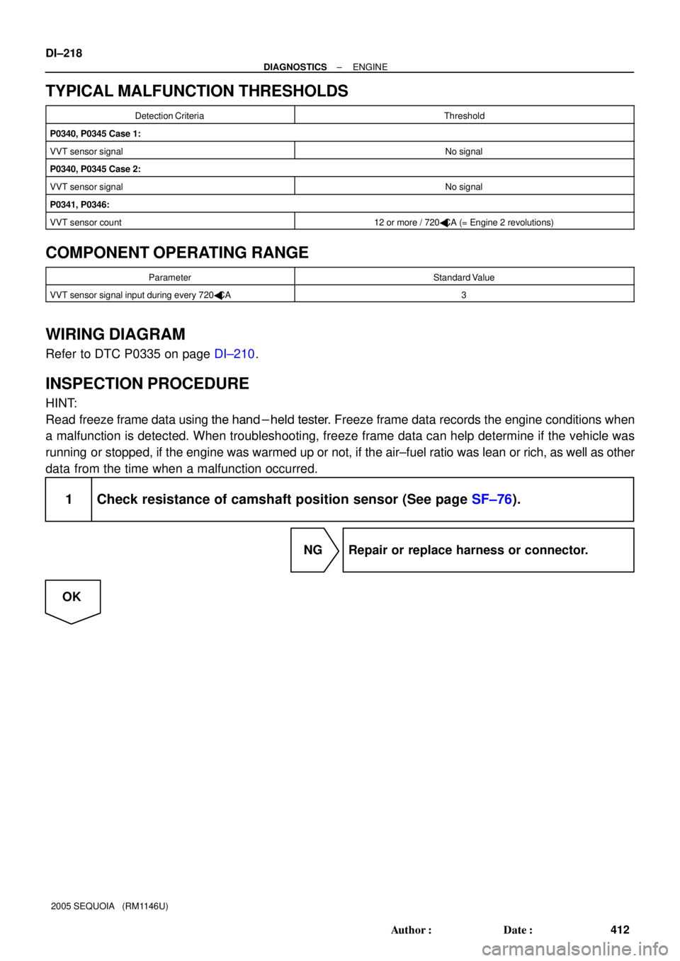
DI±218
± DIAGNOSTICSENGINE
412 Author�: Date�:
2005 SEQUOIA (RM1146U)
TYPICAL MALFUNCTION THRESHOLDS
Detection CriteriaThreshold
P0340, P0345 Case 1:
VVT sensor signalNo signal
P0340, P0345 Case 2:
VVT sensor signalNo signal
P0341, P0346:
VVT sensor count12 or more / 720�CA (= Engine 2 revolutions)
COMPONENT OPERATING RANGE
ParameterStandard Value
VVT sensor signal input during every 720�CA3
WIRING DIAGRAM
Refer to DTC P0335 on page DI±210.
INSPECTION PROCEDURE
HINT:
Read freeze frame data using the hand-held tester. Freeze frame data records the engine conditions when
a malfunction is detected. When troubleshooting, freeze frame data can help determine if the vehicle was
running or stopped, if the engine was warmed up or not, if the air±fuel ratio was lean or rich, as well as other
data from the time when a malfunction occurred.
1 Check resistance of camshaft position sensor (See page SF±76).
NG Repair or replace harness or connector.
OK