Page 3646 of 4323

BO4S5±01
H24375
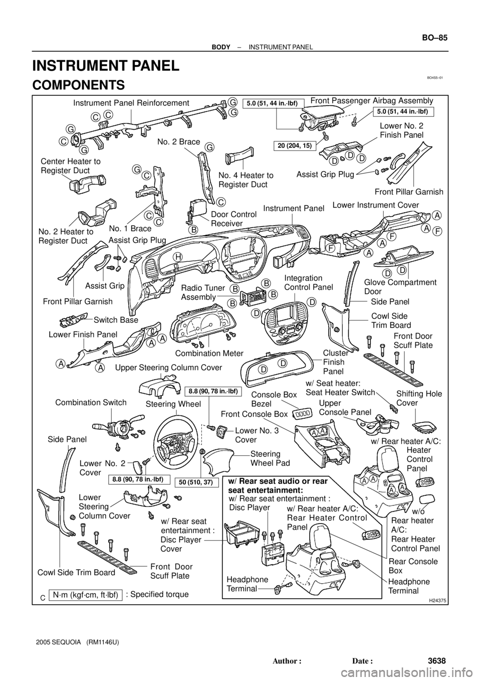
Instrument Panel ReinforcementFront Passenger Airbag Assembly
Lower No. 2
Finish Panel
No. 2 Brace
Center Heater to
Register Duct
No. 1 Brace
No. 2 Heater to
Register DuctNo. 4 Heater to
Register DuctAssist Grip Plug
Instrument Panel
Radio Tuner
Assembly Assist Grip
Front Pillar Garnish
Combination Meter Switch Base
Lower Finish PanelGlove Compartment
Door
Side Panel
Cowl Side
Trim Board
Cluster
Finish
Panel
Console Box
BezelUpper
Console Panel w/ Seat heater:
Seat Heater Switch
Steering
Wheel Pad Front Console Box
Lower
Steering
Column Cover
Front Door
Scuff Plate
N´m (kgf´cm, ft´lbf): Specified torque
CC
G
G
C
G
G
G
GC
CC
C
DDD
DD
A
A
A
A
AA
AA
F
FF
DD
D
DB
BB
B
5.0 (51, 44 in.´lbf)
20 (204, 15)
A
A
Headphone
Terminal
8.8 (90, 78 in.´lbf)
Lower No. 2
CoverLower No. 3
Cover
AAAA
Headphone
TerminalRear Console
Box w/ Rear seat entertainment :
w/ Rear heater A/C:
Rear Heater Control
Panel
w/ Rear seat
entertainment :
Disc Player
Coverw/ Rear heater A/C:
Disc Player
w/o
Rear heater
A/C:
Rear Heater
Control PanelHeater
Control
Panel
w/ Rear seat audio or rear
seat entertainment:
8.8 (90, 78 in.´lbf)
Steering Wheel
Upper Steering Column Cover
Front Door
Scuff Plate
Side Panel
Cowl Side Trim Board
5.0 (51, 44 in.´lbf)
Integration
Control Panel
Combination Switch
50 (510, 37)
Front Pillar Garnish
Lower Instrument Cover
Shifting Hole
Cover
Door Control
Receiver
Assist Grip Plug
H
B
± BODYINSTRUMENT PANEL
BO±85
3638 Author�: Date�:
2005 SEQUOIA (RM1146U)
INSTRUMENT PANEL
COMPONENTS
Page 3651 of 4323

H11174: 4 Clips
H11372
3 Clips
H11177
2 Clips
H16769
5 Clips
H24384
BO±90
± BODYINSTRUMENT PANEL
3643 Author�: Date�:
2005 SEQUOIA (RM1146U)
10. REMOVE LOWER FINISH PANEL
(a) Remove the 2 screws and hood lock release lever.
(b) Remove the 4 bolts and lower finish panel.
(c) Disconnect the connector.
11. REMOVE SWITCH BASE
(a) Using a screwdriver, lift up the switch base and remove it.
HINT:
Tape the screwdriver tip before use.
(b) Disconnect the connectors.
12. REMOVE NO. 2 HEATER TO REGISTER DUCT
13. REMOVE STEERING COLUMN (See page SR±14)
14. REMOVE CLUSTER FINISH PANEL
Remove the 2 screws and cluster finish panel.
15. REMOVE COMBINATION METER
(a) Remove the 4 screws.
(b) Remove the combination meter and disconnect the 4
connectors.
16. REMOVE INTEGRATION CONTROL PANEL
(a) Remove the 2 screws as shown in the illustration.
(b) Using a screwdriver, remove the integration panel, then
disconnect the connectors.
HINT:
Tape the screwdriver tip before use.
17. REMOVE RADIO TUNER ASSEMBLY
(a) Disconnect the connector.
(b) Remove the 4 bolts and radio tuner assembly.
18. REMOVE AIR CONDITIONER CONTROL ASSEMBLY
(See page AC±103)
Page 3860 of 4323
05_SEQUOIA_U (L/O 0408)
1
2005 SEQUOIA from Aug. '04 Prod. (OM34424U)
OPERATION OF INSTRUMENTS AND
CONTROLS
Overview of instruments and controls
Instrument panel overview2 . . . . . . . . . . . . . . . . . . . . . . . . . . . . . . . . . . . . .
Instrument cluster overview8 . . . . . . . . . . . . . . . . . . . . . . . . . . . . . . . . . . . .
Indicator symbols on the instrument panel10 . . . . . . . . . . . . . . . . . . . . . .
SECTION 1± 1
Page 3861 of 4323
05_SEQUOIA_U (L/O 0408)
2
2005 SEQUOIA from Aug. '04 Prod. (OM34424U)
1. Side vents
2. Instrument cluster
3. Center vents
4. Multi±information display
5. Personal lights
6. Garage door opener box or auxiliary
box
7. Electric moon roof switches
8. Side defroster outlet
9. Glove box
10. Power door lock switches
11. Power window switches
12. Power outlets
13. Seat heater switches
14. Rear console box
15. Rear air conditioning controls
16. Headphone input jacks and headphone
volume control dials
17. Input terminal adapter
18. Cup holders
19. Power rear view mirror control switches
20. Lower vent
Instrument panel overview
�View A
Page 3867 of 4323
05_SEQUOIA_U (L/O 0408)
8
2005 SEQUOIA from Aug. '04 Prod. (OM34424U)
1. Service reminder indicators and
indicator lights
2. Oil pressure gauge
3. Tachometer4. Speedometer
5. Fuel gauge
6. Engine coolant temperature gauge7. Trip meter reset knob
8. Odometer and two trip meters
9. Height control indicator lights
10. Volt meter
Instrument cluster overview
�Ty p e A
Page 4032 of 4323

05_SEQUOIA_U (L/O 0408)
173
2005 SEQUOIA from Aug. '04 Prod. (OM34424U)
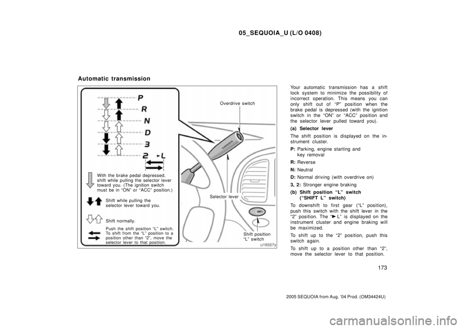
Your automatic transmission has a shift
lock system to minimize the possibility of
incorrect operation. This means you can
only shift out of ªPº position when the
brake pedal is depressed (with the ignition
switch in the ªONº or ªACCº position and
the selector lever pulled toward you).
(a) Selector lever
The shift position is displayed on the in-
strument cluster.
P:Parking, engine starting and
key removal
R:Reverse
N:Neutral
D:Normal driving (with overdrive on)
3, 2: Stronger engine braking
(b) Shift position ªLº switch
(ªSHIFT Lº switch)
To downshift to first gear (ªLº position),
push this switch with the shift lever in the
ª2º position. The ª
Lº is displayed on the
instrument cluster and engine braking will
be maximized.
To shift up to the ª2º position, push this
switch again.
To shift up to a position other than ª2º,
move the selector lever to that position.
Automatic transmission
With the brake pedal depressed,
shift while pulling the selector lever
toward you. (The ignition switch
must be in ªONº or ªACCº position.)
Shift while pulling the
selector lever toward you.
Shift normally.Selector leverOverdrive switch
Shift position
ªLº switch
Push the shift position ªLº switch.
To shift from the ªLº position to a
position other than ª2º, move the
selector lever to that position.
Page 4065 of 4323

05_SEQUOIA_U (L/O 0408)
206
2005 SEQUOIA from Aug. '04 Prod. (OM34424U)
If you need accelerationÐfor example,
when passingÐdepress the accelerator
pedal enough for the vehicle to exceed
the set speed. When you release it, the
vehicle will return to the speed set prior
to the acceleration.
CANCELLING THE PRESET SPEED
You can cancel the preset speed by:
a. Pulling the lever in the ªCANCELº di-
rection and releasing it.
b. Depressing the brake pedal.
c. Pushing ªON±OFFº button.
If the vehicle speed falls below about 40
km/h (25 mph), the preset speed will auto-
matically cancel out.
If the vehicle speed drops 16 km/h (10
mph) below the preset speed, the preset
speed will also automatically cancel out.
If the preset speed automatically cancels
out other than for the above cases, have
your vehicle checked by your Toyota deal-
er at the earliest opportunity.RESETTING TO A FASTER SPEED
Push the lever up in the ª+ RESº direction
and hold it. Release the lever when the
desired speed is attained. While the lever
is held up, the vehicle will gradually gain
speed.
However, a faster way to reset is to ac-
celerate the vehicle and then push the
lever down in the ª± SETº direction.
RESETTING TO A SLOWER SPEED
Push the lever down in the ª± SETº direc-
tion and hold it. Release the lever when
the desired speed is attained. While the
lever is held down, the vehicle speed will
gradually decrease.
However, a faster way to reset is to de-
press the brake pedal and then push the
lever down in the ª± SETº direction.
Even if you turn off the overdrive switch,
with the cruise control on, engine braking
will not be applied because the cruise
control is not cancelled. To decrease the
vehicle speed, reset to a slower speed
with the cruise control lever or depress
the brake pedal. If you use the brake
pedal, cruise control is cancelled.RESUMING THE PRESET SPEED
If the preset speed is cancelled by pulling
the control lever or by depressing the
brake pedal, pushing the lever up in the
ª+ RESº direction will restore the speed
set prior to cancellation.
CRUISE CONTROL FAILURE WARNING
If the ªCRUISEº indicator light in the
instrument cluster flashes when using the
cruise control, press the ªON±OFFº button
to turn the system off and then press it
again to turn it on.
If any of the following conditions then oc-
curs, there is some trouble in the cruise
control system.
�The indicator light does not come on.
�The indicator light flashes again.
�The indicator light goes out after it
comes on.
If this is the case, contact your Toyota
dealer and have your vehicle inspected.