Page 3037 of 4323

DISASSEMBLY
1. CHECK DRIVE SHAFT
(a) Check")
SA24M±03
F06646
F07259
W03190
Matchmarks
F06647
SST
F06648
SST
± SUSPENSION AND AXLEFRONT DRIVE SHAFT
SA±33
3029 Author�: Date�:
2005 SEQUOIA (RM1146U)
DISASSEMBLY
1. CHECK DRIVE SHAFT
(a) Check to see that there is no remarkable play in the out-
board joint.
(b) Check to see that the inboard joint slides smoothly in the
thrust direction.
(c) Check to see that there is no remarkable play in the radial
direction of the inboard joint.
(d) Check the boots for damage.
2. REMOVE INBOARD AND OUTBOARD JOINT BOOT
CLAMPS
(a) Using pliers, pinch the claws to compress the large in-
board joint boot clamp and remove it.
(b) Using a side cutter, cut the small inboard joint boot clamp
and remove it.
(c) Using a side cutter, cut the 2 outboard joint boot clamps
and remove them.
3. REMOVE INBOARD JOINT SHAFT FROM OUTBOARD
JOINT SHAFT
(a) Place matchmarks on the inboard and outboard joint
shafts.
NOTICE:
Do not punch the marks.
(b) Using a snap ring expander, pull out the outboard joint
shaft while expanding the snap ring.
4. REMOVE INBOARD AND OUTBOARD JOINT BOOTS
5. REMOVE DUST SEAL
Using SST and a press, remove the dust seal.
SST 09950±00020
6. REMOVE DUST COVER
Using SST and a press, remove the dust cover.
SST 09950±00020
Page 3039 of 4323
F07260
F07256
SST
F07257
SST
± SUSPENSION AND AXLEFRONT DRIVE SHAFT
SA±35
3031 Author�: Date�:
2005 SEQUOIA (RM1146U)
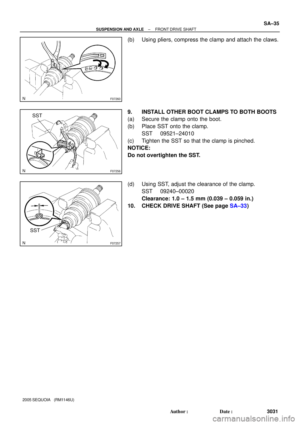
(b) Using pliers, compress the clamp and attach the claws.
9. INSTALL OTHER BOOT CLAMPS TO BOTH BOOTS
(a) Secure the clamp onto the boot.
(b) Place SST onto the clamp.
SST 09521±24010
(c) Tighten the SST so that the clamp is pinched.
NOTICE:
Do not overtighten the SST.
(d) Using SST, adjust the clearance of the clamp.
SST 09240±00020
Clearance: 1.0 ± 1.5 mm (0.039 ± 0.059 in.)
10. CHECK DRIVE SHAFT (See page SA±33)
Page 3040 of 4323

INSTALLATION
1. INSTALL DRIVE SHAFT TO DIFFERENTIAL
(a) Install a new snap ring to the inboard jo")
SA14I±10
SA±36
± SUSPENSION AND AXLEFRONT DRIVE SHAFT
3032 Author�: Date�:
2005 SEQUOIA (RM1146U)
INSTALLATION
1. INSTALL DRIVE SHAFT TO DIFFERENTIAL
(a) Install a new snap ring to the inboard joint shaft.
(b) Apply gear oil to the inboard joint shaft and differential case sliding surface.
(c) Set the snap ring with opening side facing downward.
(d) Using a brass bar and hammer, install the drive shaft.
NOTICE:
Be careful not to damage the dust cover and oil seal.
HINT:
Whether the inboard joint shaft is in contact with the pinion shaft or not can be known from the sound or feel-
ing when driving.
(e) Check that there is 2 ± 3 mm (0.08 ± 0.12 in.) of play in the axial direction.
(f) Check that the drive shaft cannot be removed by hand.
2. LH drive shaft:
INSTALL LH SHOCK ABSORBER (See page SA±70)
3. CONNECT DRIVE SHAFT TO STEERING KNUCKLE
NOTICE:
Be careful not to damage the oil seal, boots and dust seal.
4. CONNECT LOWER SUSPENSION ARM TO LOWER BALL JOINT
(a) Connect the lower suspension arm to the lower ball joint.
(b) Install the nut and a new cotter pin.
If the holes for the cotter pin are not aligned, tighten the nut further up to 60°.
HINT:
Face the hole for the cotter pin forward.
Torque: 140 N´m (1,450 kgf´cm, 103 ft´lbf)
5. INSTALL DRIVE SHAFT LOCK NUT
(a) While applying brakes, install the nut.
Torque: 235 N´m (2,400 kgf´cm, 173 ft´lbf)
(b) Install the lock cap and a new cotter pin.
If the holes for the cotter pin are not aligned, tighten the nut further up to 60°.
6. FILL DIFFERENTIAL WITH HYPOID GEAR OIL (See page SA±38)
7. INSTALL ENGINE UNDER COVER
8. INSTALL FRONT WHEEL
Torque: 110 N´m (1,150 kgf´cm, 83 ft´lbf)
Page 3042 of 4323
SA23L±04
Z00638
SST
R13369
SST
R13370
SST
R13371
SST SA±38
± SUSPENSION AND AXLEFRONT DIFFERENTIAL REAR OIL SEAL
3034 Author�: Date�:
2005 SEQUOIA (RM1146U)
REPLACEMENT
1. REMOVE ENGINE UNDER COVER
2. DRAIN DIFFERENTIAL OIL
3. REMOVE FRONT PROPELLER SHAFT
(See page PR±7)
4. REMOVE COMPANION FLANGE
(a) Using a chisel and hammer, loosen the staked part of the
nut.
(b) Using SST to hold the flange, remove the nut.
SST 09330±00021
(c) Using SST, remove the companion flange.
SST 09950±30012 (09951±03010, 09953±03010,
09954±03010, 09955±03030, 09956±03020)
5. REMOVE OIL SEAL AND OIL SLINGER
(a) Using SST, remove the oil seal.
SST 09308±10010
(b) Remove the oil slinger.
6. REMOVE REAR BEARING AND BEARING SPACER
(a) Using SST, remove the rear bearing from the drive pinion.
SST 09556±22010
(b) Remove the bearing spacer.
7. INSTALL BEARING SPACER, REAR BEARING AND
OIL SLINGER
(a) Install a new bearing spacer and place the rear bearing
and oil slinger.
Page 3043 of 4323

FA1083
SST
FA1084
R13338
Less than
5 mm (0.20 in.)
± SUSPENSION AND AXLEFRONT DIFFERENTIAL REAR OIL SEAL
SA±39
3035 Author�: Date�:
2005 SE")
R13368
SST
R13374
SST
4.5 ± 0.3 mm
(0.177 ± 0.012 in.)
FA1083
SST
FA1084
R13338
Less than
5 mm (0.20 in.)
± SUSPENSION AND AXLEFRONT DIFFERENTIAL REAR OIL SEAL
SA±39
3035 Author�: Date�:
2005 SEQUOIA (RM1146U)
(b) Using SST and the companion flange, install the rear
bearing, then remove the companion flange.
SST 09950±30012 (09951±03010, 09953±03010,
09954±03010, 09955±03030, 09956±03020)
8. INSTALL OIL SEAL
(a) Coat a new oil seal lip with MP grease.
(b) Using SST and a hammer, install the oil seal.
SST 09554±22010
Oil seal drive in depth: 4.5 ± 0.3 mm (0.177 ± 0.012 in.)
9. INSTALL COMPANION FLANGE
(a) Place the companion flange on the drive pinion.
(b) Coat the threads of a new nut with hypoid gear oil.
(c) Using SST to hold the flange, torque the nut.
SST 09330±00021
Torque: 108 N´m (1,100 kgf´cm, 80 ft´lbf)
10. ADJUST DRIVE PINION PRELOAD
(See page SA±50)
11. STAKE DRIVE PINION NUT
12. INSTALL FRONT PROPELLER SHAFT
(See page PR±9)
13. FILL DIFFERENTIAL WITH HYPOID GEAR OIL
Torque: 39 N´m (400 kgf´cm, 29 ft´lbf)
Oil type: Hypoid gear oil API GL±5
Recommended oil viscosity: SAE 75W±90
Capacity: 1.15 liters (1.22 US qts, 1.01 Imp. qts)
14. INSTALL ENGINE UNDER COVER
Page 3045 of 4323
F06628
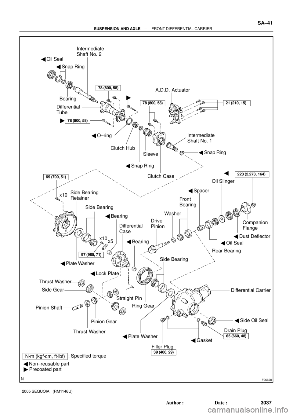
� Oil Seal
� Snap Ring
Bearing
Intermediate
Shaft No. 2
Differential
Tube
�78 (800, 58)
78 (800, 58)
�
A.D.D. Actuator
21 (210, 15)
� Snap Ring
Intermediate
Shaft No. 1
Clutch Case
Sleeve
� Snap Ring
� O±ring
Clutch Hub
�
Oil Slinger
� Spacer
Companion
Flange
� Dust Deflector
� Oil Seal
Rear Bearing
Washer
Drive
Pinion
Front
Bearing
Differential Carrier
� Side Oil Seal
Drain Plug
65 (660, 48)� Gasket
Filler Plug
39 (400, 29)
Ring Gear
69 (700, 51)
x10Side Bearing
Retainer
Side Bearing
x10
x5
� Plate Washer
97 (985, 71)
� Lock Plate
� Bearing
Differential
Case
� Bearing
Side Bearing
Straight Pin
� Plate Washer
Thrust Washer
Side Gear
Pinion Shaft
Pinion Gear
Thrust Washer
� Non±reusable part
� Precoated part
N´m (kgf´cm, ft´lbf): Specified torque
78 (800, 58)
223 (2,273, 164)
± SUSPENSION AND AXLEFRONT DIFFERENTIAL CARRIER
SA±41
3037 Author�: Date�:
2005 SEQUOIA (RM1146U)
Page 3047 of 4323

SA23N±04
R12683
SST
FA1158
F06631
± SUSPENSION AND AXLEFRONT DIFFERENTIAL CARRIER
SA±43
3039 Author�: Date�:
2005 SEQUOIA (RM1146U)
DISASSEMBLY
1. CHECK COMPANION FLANGE R")
W00493
30 mm (1.18 in.)
SA23N±04
R12683
SST
FA1158
F06631
± SUSPENSION AND AXLEFRONT DIFFERENTIAL CARRIER
SA±43
3039 Author�: Date�:
2005 SEQUOIA (RM1146U)
DISASSEMBLY
1. CHECK COMPANION FLANGE RUNOUT
Using a dial indicator, measure the vertical and lateral runout of
the companion flange.
Maximum runout: 0.10 mm (0.0039 in.)
If the runout exceeds the maximum, replace the companion
flange.
2. CHECK RING GEAR BACKLASH
Using SST and a dial indicator, measure the ring gear backlash.
SST 09564±32011
Backlash: 0.1 ± 0.18 mm (0.0039 ± 0.0071 in.)
HINT:
Measure at 3 or more points on the circumference of the ring
gear.
If the backlash is not within the specified value, adjust the side
bearing preload or repair as necessary.
3. MEASURE DRIVE PINION PRELOAD
Using a torque wrench, measure the preload using the back-
lash between the drive pinion and ring gear.
Preload (at starting):
0.6 ± 1.0 N´m (6 ± 10 kgf´cm, 5.2 ± 8.7 in.´lbf)
4. CHECK TOTAL PRELOAD
Using a torque wrench, measure the total preload with the teeth
of the drive pinion and ring gear in contact.
Total preload (at starting):
Drive pinion preload plus 0.4 ± 0.6 N´m (4 ± 6 kgf´cm,
3.5 ± 5.2 in.´lbf)
If necessary, disassemble and inspect the differential.
5. REMOVE A.D.D. ACTUATOR
(a) Remove the 4 bolts.
(b) Using a hammer handle, remove the actuator.
Page 3049 of 4323
SA2348
SST
Z00641
SST
W04006
R02482
SST
R13226
± SUSPENSION AND AXLEFRONT DIFFERENTIAL CARRIER
SA±45
3041 Author�: Date�:
2005 SEQUOIA (RM1146U)
11. REMOVE OIL SEAL AND OIL SLINGER
(a) Using SST, remove the oil seal.
SST 09308±10010
(b) Remove the oil slinger.
12. REMOVE REAR BEARING AND BEARING SPACER
(a) Using SST, remove the rear bearing from the drive pinion.
SST 09556±22010
(b) Remove the bearing spacer.
13. REMOVE SIDE BEARING RETAINER
Remove the 10 bolts and tap out the retainer with a plastic ham-
mer.
14. REMOVE DIFFERENTIAL CASE ASSEMBLY
15. REMOVE DRIVE PINION FROM DIFFERENTIAL CAR-
RIER
16. REMOVE DRIVE PINION FRONT BEARING
Using SST and a press, remove the bearing and washer from
the drive pinion.
SST 09950±00020
HINT:
If the drive pinion or ring gear is damaged, replace them as a
set.
17. REMOVE DRIVE PINION BEARING OUTER RACES
(a) Using a brass bar and hammer, remove the front bearing
outer race.