Page 2710 of 4323

RH Bank LH Bank
Front
Outside Mark
(Protrusion)
A05101
A05099
Painted
Mark Front90°
90°
± ENGINE MECHANICALCYLINDER BLOCK
EM±123
2702 Auth")
A05106
A05107A05108A05174
Front
Outside Mark
(Protrusion)
RH Bank LH Bank
Front
Outside Mark
(Protrusion)
A05101
A05099
Painted
Mark Front90°
90°
± ENGINE MECHANICALCYLINDER BLOCK
EM±123
2702 Author�: Date�:
2005 SEQUOIA (RM1146U)
11. PLACE CONNECTING ROD CAP ON CONNECTING
ROD
(a) Match the numbered connecting rod cap with the con-
necting rod.
(b) Align the pin groove of the connecting rod cap with the
pins of the connecting rod, and install the connecting rod
cap.
(c) Check that the outside mark of the connecting rod cap is
facing in correct direction.
12. INSTALL CONNECTING ROD CAP BOLTS
HINT:
�The connecting rod cap bolts are tightened in 2 progres-
sive steps (steps (b) and (d)).
�If any one of the connecting rod cap bolts is broken or de-
formed, replace it.
(a) Apply a light coat of engine oil on the threads and under
the heads of the connecting rod cap bolts.
(b) Install and alternately tighten the 2 connecting rod cap
bolts in several passes.
Torque: 24.5 N´m (250 kgf´cm, 18 ft´lbf)
If any one of the connecting rod cap bolts does not meet the
torque specification, replace the connecting rod cap bolts.
(c) Mark the front of the connecting cap bolt with paint.
(d) Retighten the cap bolts by 90° as shown.
(e) Check that the painted mark is now at a 90° angle to the
front.
(f) Check that the crankshaft turns smoothly.
13. CHECK CONNECTING ROD THRUST CLEARANCE
(See page EM±101)
Page 2726 of 4323
 CONTROL SYSTEM
2718 Author�: Date�:
2005 SEQUOIA (RM1146U)
(d) When not using a hand±held tester:
Ope")
B16489
Battery
B06545
Vacuum Gauge
B17595
EC±10
± EMISSION CONTROLEVAPORATIVE EMISSION (EVAP) CONTROL SYSTEM
2718 Author�: Date�:
2005 SEQUOIA (RM1146U)
(d) When not using a hand±held tester:
Operation of the VSV for the EVAP.
(1) Disconnect the VSV for the EVAP connector.
(2) Connect leads from the positive (+) and negative (±)
battery terminals to the VSV for EVAP terminals.
(3) Start the engine.
(e) Check the vacuum when the engine idles.
Vacuum:
Maintain between 0.368 and 19.713 in.Hg (5 to 268
in.Aq) for over 5 seconds
HINT:
If the vacuum does not change, the hose connecting the VSV
and the service port is loose or blocked, or the VSV is malfunc-
tioning.
(f) When using a hand±held tester:
Conclude operation of the VSV for EVAP.
(1) Stop the engine.
(2) Disconnect the hand±held tester from the DLC3.
(g) When not using a hand±held tester:
Conclude operation of the VSV for EVAP.
(1) Stop the engine.
(2) Disconnect the positive (+) and negative (±) leads
of the battery from the VSV for EVAP terminals.
(3) Connect the VSV for EVAP connector.
(h) Disconnect the vacuum gauge from the EVAP service
port on the purge line.
(i) Connect a pressure gauge to the EVAP service port on
the purge line.
(j) Check the pressure.
(1) Prepare a rubber hose that has an inside diameter
of 15 to 18.5 mm.
(2) Disconnect the atmospheric side hose of the pump
module.
(3) Connect the prepared rubber hose to the pump
module, and pinch the rubber hose with the clip to
prevent air from entering into the canister passage.
Page 2745 of 4323

B16499
Fulcrum
Length
30 cm
SST
B02714
CORRECT
WRONG
Delivery Pipe O±Ring
B04939
Delivery
Pipe
Intake
Manifold O±Ring
Grommet
Injector
Insulator
B17532
Quick Type
Disconnect
B11684
Quick Type
Push
Pull
± SFISFI SYSTEM
SF±3
2737 Author�: Date�:
2005 SEQUOIA (RM1146U)
(3) Using SST, tighten the union bolt to the specified
torque.
SST 09612±24014 (09617±24011)
Torque:
33 N´m (340 kgf´cm, 24 ft´lbf) for use with SST
39 N´m (400 kgf´cm, 29 ft´lbf)
HINT:
Use a torque wrench with a fulcrum length of 30 cm (11.81 in.).
(c) Observe the following precautions when removing or
installing the injectors.
(1) Never reuse the O±ring.
(2) When placing a new O±ring on the injector, take
care not to damage it in any way.
(3) Coat a new O±ring with spindle oil or gasoline be-
fore installing. Never use engine, gear or brake oil.
(d) Install the injector to the delivery pipe and intake manifold
as shown in the illustration.
Before installing the injector, apply spindle oil or gasoline
on the place where the delivery pipe or the intake man-
ifold touches the O±ring of the injector.
(e) Observe the following when disconnecting the fuel tube
connector (quick type):
(1) Check if there is any dirt in the pipe and around the
connector before disconnecting the fuel tube con-
nector. If necessary, clean the dirt away.
(2) Disconnect the fuel pipe clamp from the connector.
(3) Be sure to disconnect them by hand.
(4) When the connector and the pipe are stuck, push
and pull the connector. Then disconnect and pull it
out. Do not use any tools at this time.
(5) Check if there is any dirt or other foreign matter on
the seal surface of the disconnected pipe. If neces-
sary, clean the dirt away.
(6) Do not damage the disconnected pipe and connec-
tor and prevent intrusion of foreign objects by cover-
ing them with a plastic bag.
Page 2747 of 4323

B10036
Metallic Type
Pull Connector
B10485
Metallic Type
Push
B10485
Metallic Type
Pull
± SFISFI SYSTEM
SF±5
2739 Author�: Date�:
2005 SEQUOIA")
B10035
Metallic Type
SST
Insert Retainer
(at 4 places)
B10036
Metallic Type
Pull Connector
B10485
Metallic Type
Push
B10485
Metallic Type
Pull
± SFISFI SYSTEM
SF±5
2739 Author�: Date�:
2005 SEQUOIA (RM1146U)
(3) Turn the SST, align the retainers inside the connec-
tor with the SST chamfered parts and insert the SST
into the connector.
(4) While holding the SST, pull the connector towards
the SST to put the retainers on the SST chamfered
parts.
(5) Slide the SST and connector together towards the
fuel tube assembly.
(h) Observe the following when connecting the fuel tube con-
nector (metallic type):
(1) Check if there is any damage or foreign objects in
the connected part of the pipe.
(2) Match the axis of the connector with the axis of the
pipe, and push into the connector until a ºclickº
sound is heard. If the connection is tight, apply a
small amount of fresh engine oil on the tip of the
pipe.
(3) After finishing the connection, pull the pipe and the
connector to ensure it is secure.
(4) Check to make sure no fuel leak is present.
If the result is not specified, repair or replace.
(i) Observer the following when handling the nylon tube:
(1) Pay attention not to turn the connected part of the
nylon tube and the quick connector with tube when
connecting them.
(2) Pay attention not to kink the nylon tube.
(3) Do not remove the nylon tube.
(4) Do not close the piping with the nylon tube by bend-
ing it.
Page 2748 of 4323

(j) Check that there is any fuel leak after maintenance any-
wh")
D13872
Hand±Held Tester
DLC3
CAN VIM
B16500
Fuel Return Hose
Pinch
SF±6
± SFISFI SYSTEM
2740 Author�: Date�:
2005 SEQUOIA (RM1146U)
(j) Check that there is any fuel leak after maintenance any-
where on the fuel system.
(1) Connect a hand±held tester to the Controller Area
Network Vehicle Interface Module (CAN VIM). Then
connect the CAN VIM to the Date Link Connector 3
(DLC3).
(2) Turn the ignition switch ON and push the hand±held
tester main switch ON.
NOTICE:
Do not start the engine.
(3) Enter the following menus: DIAGNOSIS / EN-
HANCED OBDII / ACTIVE TEST / FUEL PUMP /
SPD.
(4) Please refer to the hand±held tester operator's
manual for further details.
(5) Pinch the fuel return hose.
The pressure in the high pressure line will rise to
approx. 392 kPa (4 kgf/cm
2, 57 psi). In this state,
check to see that there are no leaks from any part
of the fuel system.
NOTICE:
Always pinch the hose. Avoid bending as it may cause the
hose to crack.
(6) Turn the ignition switch OFF.
(7) Disconnect the hand±held tester and CAN VIM
from the DLC3.
Page 2751 of 4323
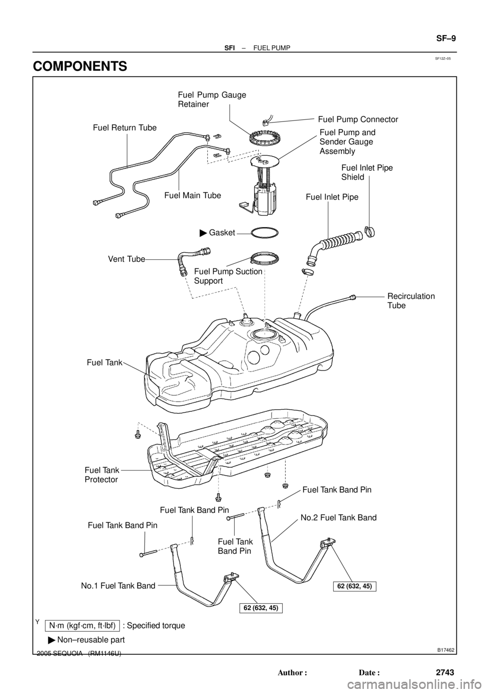
SF12Z±05
B17462
N´m (kgf´cm, ft´lbf) : Specified torque
� Non±reusable partFuel Inlet Pipe
Shield
No.1 Fuel Tank Band
� GasketFuel Pump and
Sender Gauge
Assembly
Fuel TankVent Tube
No.2 Fuel Tank Band
Fuel Inlet Pipe
Fuel Tank Band Pin
62 (632, 45)
Fuel Tank
Protector
Fuel Tank Band Pin
Fuel Return Tube
62 (632, 45)
Fuel Tank
Band Pin
Fuel Tank Band Pin
Recirculation
Tube
Fuel Main Tube
Fuel Pump Connector
Fuel Pump Gauge
Retainer
Fuel Pump Suction
Support
± SFIFUEL PUMP
SF±9
2743 Author�: Date�:
2005 SEQUOIA (RM1146U)
COMPONENTS
Page 2758 of 4323
SF1XF±01
B17549
B17548
B17609
B17546
B17542
SF±16
± SFIFUEL PUMP
2750 Author�: Date�:
2005 SEQUOIA (RM1146U)
REASSEMBLY
1. REMOVE FUEL SUCTION PLATE NO.2
(a) Install the 2 springs and suction plate No.2 to the suction
plate No.1.
(b) Using a needle±nose pliers, install the 2 new E±rings to
the suction plate No.2.
2. INSTALL FUEL PUMP
(a) Apply a light coat of gasoline or spindle oil to a new O±
ring, and install it to the fuel pump.
(b) Connect the fuel pump harness connector to the fuel
pump.
(c) Install the fuel pump with the suction filter to the fuel filter.
3. INSTALL FUEL FILTER
Install the fuel filter to the fuel sub±tank.
Page 2775 of 4323
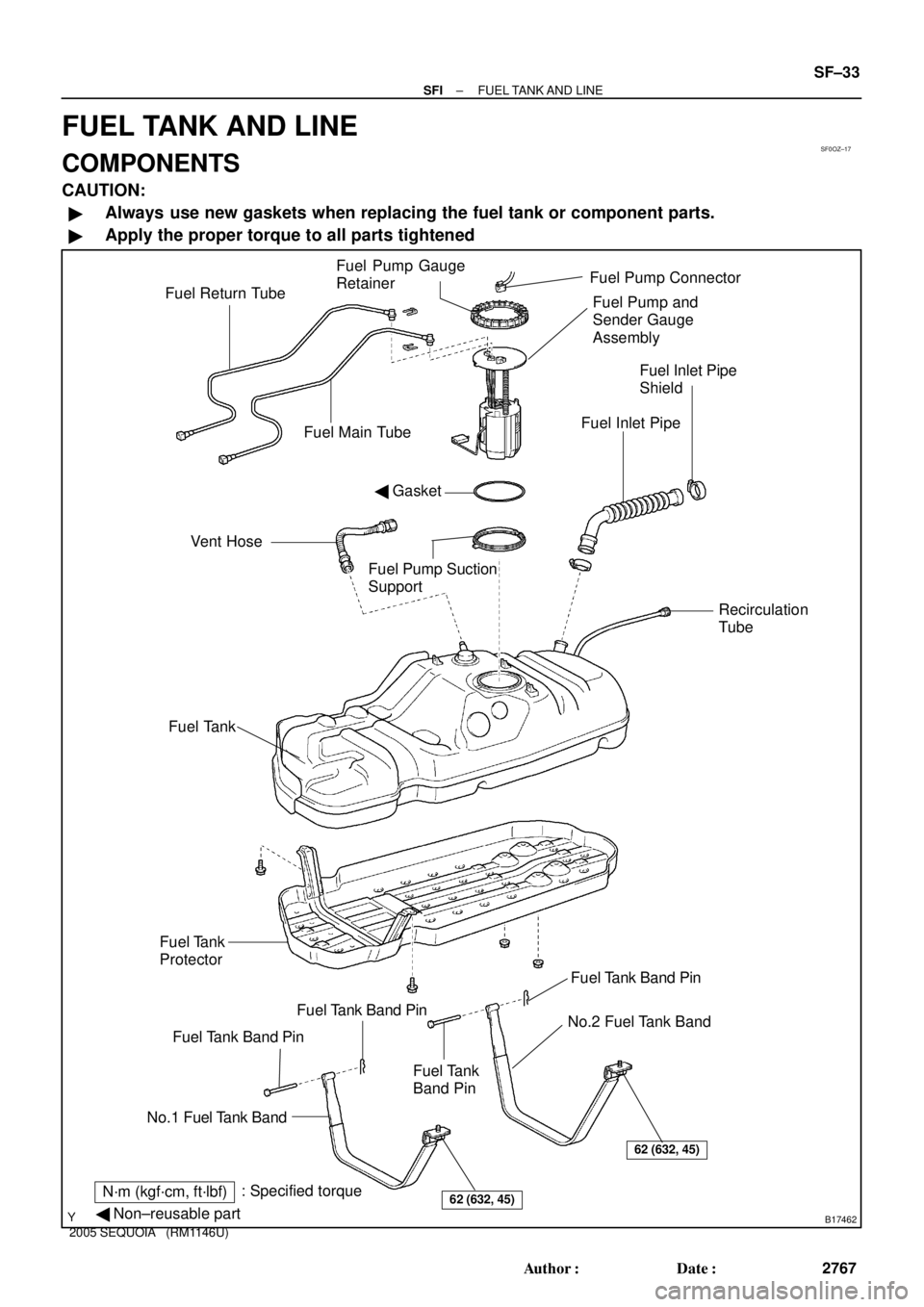
SF0OZ±17
B17462
Fuel Inlet Pipe
Shield
No.1 Fuel Tank Band
N´m (kgf´cm, ft´lbf): Specified torque
� Non±reusable part
� GasketFuel Pump and
Sender Gauge
Assembly
Fuel TankVent Hose
No.2 Fuel Tank Band
Fuel Inlet Pipe
Fuel Tank Band Pin
62 (632, 45)
Fuel Tank
Protector
Fuel Tank Band Pin
Fuel Return Tube
62 (632, 45)
Fuel Tank
Band Pin
Fuel Tank Band Pin
Recirculation
Tube
Fuel Main Tube
Fuel Pump ConnectorFuel Pump Gauge
Retainer
Fuel Pump Suction
Support
± SFIFUEL TANK AND LINE
SF±33
2767 Author�: Date�:
2005 SEQUOIA (RM1146U)
FUEL TANK AND LINE
COMPONENTS
CAUTION:
�Always use new gaskets when replacing the fuel tank or component parts.
�Apply the proper torque to all parts tightened