Page 2236 of 4323
I28353
DI±2034
± DIAGNOSTICSAUDIO SYSTEM
2228 Author�: Date�:
2005 SEQUOIA (RM1146U)
CD sound skips
HINT:
�The sound may skid when driving on an unpaved road.
�Sudden temperature changes in the cabin will cause condensation inside the CD player and prevent
it from playing.
INSPECTION PROCEDURE
1 Disc cleaning.
PREPARATION:
Disc cleaning
If the disc gets dirty, clean the disc by wiping the surface
from the center to outside in a radial direction a with a soft
cloth.
NOTICE:
Do not use a conventional record cleaner or anti±static pre-
servative.
OK:
Malfunction disappears.
OK End.
NG
2 Replace CD with another and recheck.
CHECK:
Replace the CD with another and recheck.
Replace the CD with another normal one to see if the same trouble occurs again.
OK:
Malfunction disappears.
OK End.
NG
DIDA8±01
Page 2243 of 4323
I28354
HeadCapstan
Pinch Roller
± DIAGNOSTICSAUDIO SYSTEM
DI±2041
2235 Author�: Date�:
2005 SEQUOIA (RM1146U)
3 Clean head and check operation.
PREPARATION:
Head cleaning
(1) Raise the cassette door with your finger. Using a
pencil or similar object, push in the guide.
(2) Using a cleaning pen or cotton applicator soaked in
cleaner, clean the head surface, pinch rollers and
capstans.
CHECK:
Check if the same trouble occurs again.
OK:
Malfunction disappears.
NG Replace radio receiver assy.
OK
End.
Page 2245 of 4323
I28354
HeadCapstan
Pinch Roller
± DIAGNOSTICSAUDIO SYSTEM
DI±2043
2237 Author�: Date�:
2005 SEQUOIA (RM1146U)
3 Clean head and check operation.
PREPARATION:
Head cleaning
(1) Raise the cassette door with your finger. Using a
pencil or similar object, push in the guide.
(2) Using a cleaning pen or cotton applicator soaked in
cleaner, clean the head surface, pinch rollers and
capstans.
CHECK:
Check if the same trouble occurs again.
OK:
Malfunction disappears.
NG Replace radio receiver assy.
OK
End.
Page 2260 of 4323
DIDAM±01
I28496
B±O
24R24
Rear Seat Audio
Controller Assy
ACC
+B
17
GND 1228 C
4 3A36
ACC Cut
Relay
B 12 1Sub J/B No.3
3A
ID2 W±R
J/C
L±Y1
2
IA1 26 L±R
L±R
2B3
2C8
2D Engine Room J/B
ECU±BShort Pin
1 Instrument Panel J/B
W±R
AM11
3 2RAD No.2
W 1
P6
ALT
1B
BatteryLG To ECM
GR
RSE
2 2
1Engine Room R/B No.2J37
ID221
IMLG 3A
LG
12
ID2 J38
L±R
2 12
W±LRAD No.1
W±R
W±L 1
2B
3
AM1B
ACC
I18
Ignition SW 1C
1C 1E1F
1J
1LGR
PW±R
GR
W±B 58
4F10
Fusible Link Block DI±2058
± DIAGNOSTICSREAR SEAT AUDIO SYSTEM
2252 Author�: Date�:
2005 SEQUOIA (RM1146U)
CIRCUIT INSPECTION
Power source circuit (Rear seat audio controller)
CIRCUIT DESCRIPTION
This circuit provides the power to the rear seat audio controller.
WIRING DIAGRAM
Page 2312 of 4323
I28486
J/C Sub J/B No.3
R2332 Multi±display Controller Sub±assy
ACC
R2316
+B1
R2329
GND IF3
1
IFC
4 3A36
ACC
Cut Relay
B 1
I18
Ignition SW12
12 3A W±R
W±R
1To ECM
IA126
L±R L±R
2D1
2C8Engine Room J/B
RAD No. 1
ECU±BShort Pin 3
W±L2
W±R 1C
3
1E 1J
W
IL1
IC6AM1
8
F10
FL Block
ALT
54
B
Battery
IM13
LG GR GR
L±Y GR
2 2 Engine Room R/B No. 2
Y
IF33
W±B 3AW±R
1
IF3
22B
P
3
ACCAM1
BB 1 2 W±LB±O
J37 J38
L±YY
RAD No. 2 1Instrument Panel J/B
2
1RSE
2C P DI±2110
± DIAGNOSTICSREAR SEAT ENTERTAINMANT SYSTEM
2304 Author�: Date�:
2005 SEQUOIA (RM1146U)
Power source circuit (Multi±display controller sub±assy)
CIRCUIT DESCRIPTION
This circuit provides power to the multi±display controller sub±assy.
WIRING DIAGRAM
DIDB5±01
Page 2349 of 4323
I28598
Multi±display
Controller Sub±assy
LG28
RMUT
IF316
R23
R±W
LG12
LMUT IF34
R23
R±G RMU
MUTE Radio Receiver Assy
19
R19
6
R20 w/o Navigation System:
I28598
Multi±display
Controller Sub±assy
LG28
RMUT
IF316
R23
R±W
LG12
LMUT IF34
R23
R±G RMUT
MUTE Radio and Navigation Assy
19
R27
6
R28 w/ Navigation System:
± DIAGNOSTICSREAR SEAT ENTERTAINMANT SYSTEM
DI±2147
2341 Author�: Date�:
2005 SEQUOIA (RM1146U)
Mute signal circuit (Radio receiver assy / Radio and navigation
assy ± Multi±display controller sub±assy)
CIRCUIT DESCRIPTION
The multi±display controller sub±assy controls the volume according to the MUTE signal from the radio re-
ceiver assy or radio and navigation assy.
The MUTE signal is sent to reduce noise and a popping sound generated when the mode, etc. is switched.
WIRING DIAGRAM
DIDBK±01
Page 2355 of 4323

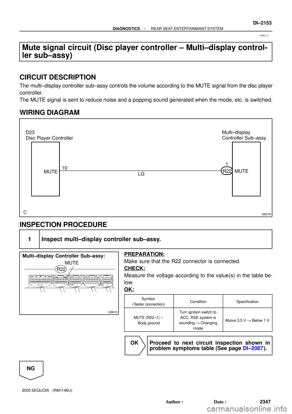
I28378
Multi±display
Controller Sub±assy
LG1
MUTE R22
MUTE D23
Disc Player Controller
10
I28610
R22
MUTE Multi±display Controller Sub±assy:
± DIAGNOSTICSREAR SEAT ENTERTAINMANT SYSTEM
DI±2153
2347 Author�: Date�:
2005 SEQUOIA (RM1146U)
Mute signal circuit (Disc player controller ± Multi±display control-
ler sub±assy)
CIRCUIT DESCRIPTION
The multi±display controller sub±assy controls the volume according to the MUTE signal from the disc player
controller.
The MUTE signal is sent to reduce noise and a popping sound generated when the mode, etc. is switched.
WIRING DIAGRAM
INSPECTION PROCEDURE
1 Inspect multi±display controller sub±assy.
PREPARATION:
Make sure that the R22 connector is connected.
CHECK:
Measure the voltage according to the value(s) in the table be-
low.
OK:
Symbol
(Tester connection)ConditionSpecification
MUTE (R22±1) ±
Body ground
Turn ignition switch to
ACC, RSE system is
sounding "Changing
mode
Above 3.5 V " Below 1 V
OK Proceed to next circuit inspection shown in
problem symptoms table (See page DI±2087).
NG
DIDBL±01
Page 2368 of 4323

I28189
Navigation performed even where the
GPS radio wave does not reach.
� In a tunnel
� In an indoor parking lot
� Between tall buildings
� Under an overpass
� On a forest or tree±lined path
Autonomous navigation
Autonomous navigation and
GPS navigationGPS satellite DI±2166
± DIAGNOSTICSNAVIGATION SYSTEM
2360 Author�: Date�:
2005 SEQUOIA (RM1146U)Operation
Description
Vehicle Position Calculation
The navigation ECU calculates the current vehicle position (direction and current
position) using the direction deviation signal from the gyro sensor and the running
distance signal from the vehicle speed sensor and creates the driving route.
Map Display processingThe navigation ECU displays the vehicle track on the map by processing the ve-
hicle position data, vehicle running track, and map data from the map disc.
Map MatchingThe map data from the map disc is compared to the vehicle position and running
track data. Then, the vehicle position is matched with the nearest road.
GPS Correction
The vehicle position is matched to the position measured by GPS. Then, the mea-
surement position data from the GPS unit is compared with the vehicle position and
running track data. If the position is widely different, the GPS measurement position
is used.
Distance Correction
The running distance signal from the vehicle speed sensor includes the error
caused by tire wear and slippage between the tires and road surface. Distance
correction is performed to account for this. The navigation ECU automatically off-
sets the running distance signal to make up for the difference between it and the
distance data of the map. The offset is automatically updated.
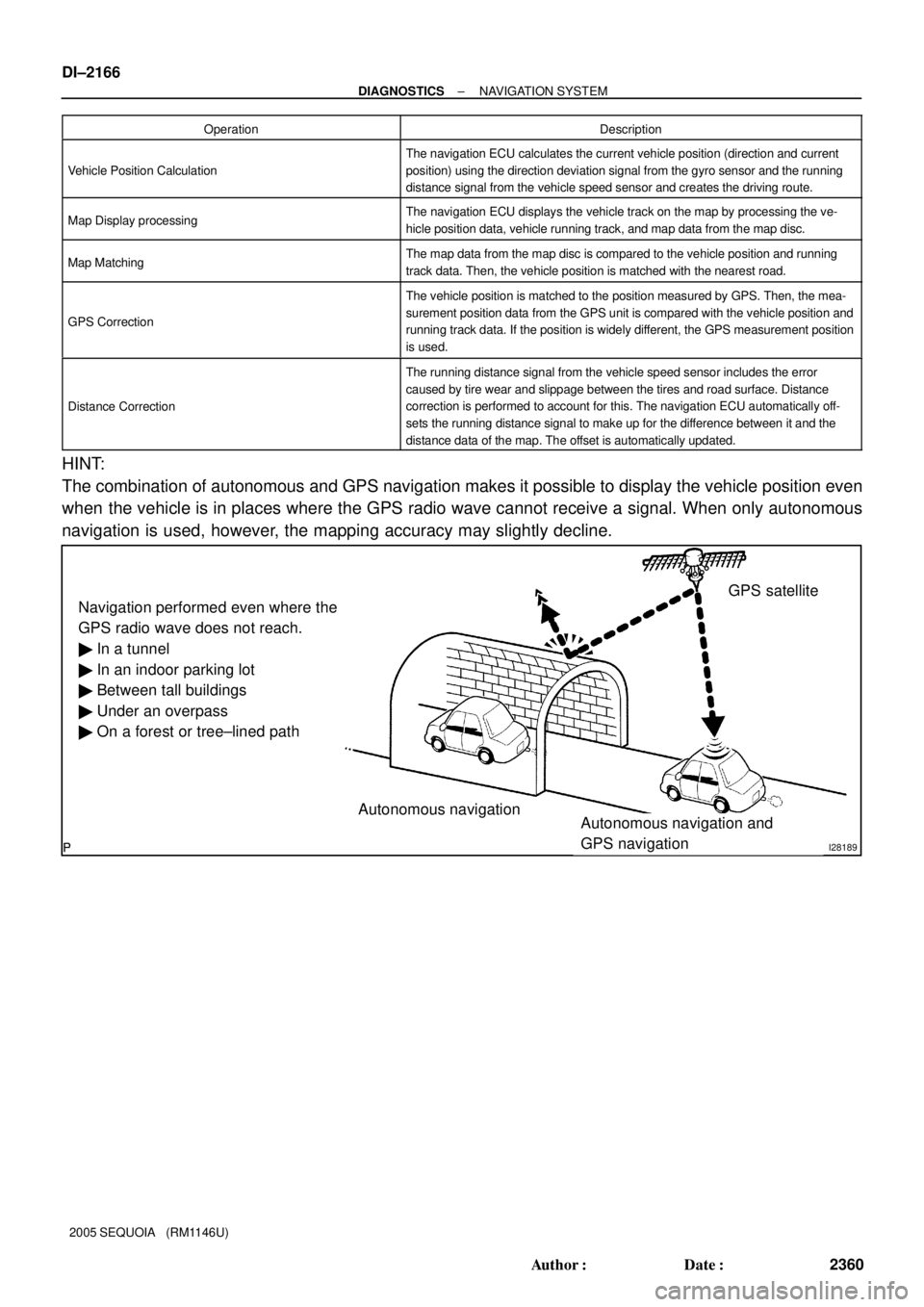
HINT:
The combination of autonomous and GPS navigation makes it possible to display the vehicle position even
when the vehicle is in places where the GPS radio wave cannot receive a signal. When only autonomous
navigation is used, however, the mapping accuracy may slightly decline.