Page 1879 of 4323
CLOSE/UP
(OPEN/DOWN)
SWITCHON
OFF
Close
(Down)
Roof OperationStop Forced Operation Reverse
Stop
Close (Down)
Close Position Approx. 10 sec.
± DIAGNOSTICSSLIDING ROOF SYSTEM
DI±1677
1871 Author�: Date�:
2005 SEQUOIA (RM1146U)
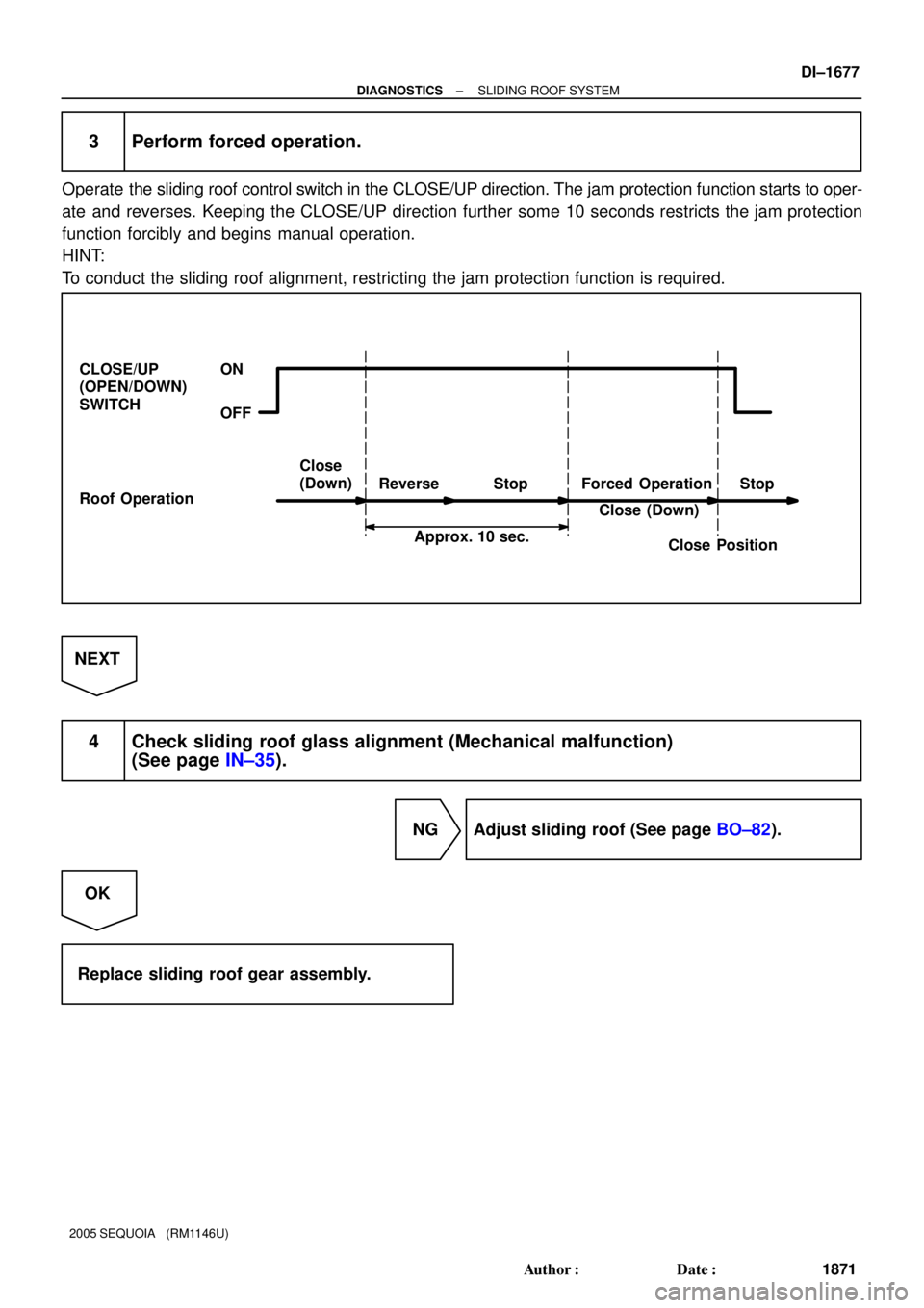
3 Perform forced operation.
Operate the sliding roof control switch in the CLOSE/UP direction. The jam protection function starts to oper-
ate and reverses. Keeping the CLOSE/UP direction further some 10 seconds restricts the jam protection
function forcibly and begins manual operation.
HINT:
To conduct the sliding roof alignment, restricting the jam protection function is required.
NEXT
4 Check sliding roof glass alignment (Mechanical malfunction)
(See page IN±35).
NG Adjust sliding roof (See page BO±82).
OK
Replace sliding roof gear assembly.
Page 1903 of 4323
I28515
Engine Room J/B
Body ECU
Instrument Panel J/B SECURITY
I18
Ignition SWBDR
ACC
BECU S+B B6 L±W
IA5 2D
2C2H
1C 1E
1G
1L
1G
1G1C 1C 1J12
3
45
6 7
10
11
5
6 2
58 1101332
1
6L±W
IA510
B6
B7
B6 1
2 1
8
12DOOR No. 2
ECU±BShort
Pin
2W±L
W±L
W±R
B B
WGR
W±R
P RAD No. 2
AM1
WSH
ECU±IG12AM1
ACC
B7 IG1 W±L
ALT R/B
F10
FL Block
BatteryL±YB±RB±Y
B
W±BB7
B6
IE 12
IG
WIG
GND1 1W±R 12
3A 3ESub J/B No. 3
4Engine Room R/B No. 2
± DIAGNOSTICSBODY CONTROL SYSTEM
DI±1701
1895 Author�: Date�:
2005 SEQUOIA (RM1146U)
WIRING DIAGRAM
Page 1908 of 4323

I24351
Body ECU
11 3
21 5
B 5W
1G TAILLIGHT Relay
To Taillight
F10
Fusible Link BlockLG
B7
ALTTRLY 2 1L
81
BatteryInstrument Panel J/B
LG
DDJ/9
J/C DI±1706
± DIAGNOSTICSBODY CONTROL SYSTEM
1900 Author�: Date�:
2005 SEQUOIA (RM1146U)
Taillight Relay Circuit
CIRCUIT DESCRIPTION
TAILLIGHT relay will be ºONº by operating the light control switch. The transistor which activates the tail light
relay has two sorts: one is activated by the light control switch for fail safe and the other is activated by CPU.
When the theft deterrent system is activated, it causes the transistor in the ECU to switch ON and OFF at
approximately 0.4 sec. intervals. This switches the TAILLIGHT relay ON and OFF, and thus flashing the tail-
lights (See the wiring diagram below).
In this condition, if any of the following operations is done, the transistor in the ECU goes OFF and the TAIL-
LIGHT relay switches OFF, and thus stopping the taillights flashing:
(1) Unlock the front LH or RH door with a key.
(2) Turn the ignition switch to ACC or ON position.
(3) Unlock the doors with the wireless door lock control system.
(4) Wait for approximately 60 seconds.
WIRING DIAGRAM
DI6QY±15
Page 1910 of 4323
: w/ Daytime Running Light
(*2): w/o Daytime Runn")
I24144
Body ECU
MAINEngine Room J/B
HEAD Relay
Instrument Panel J/B
Battery
LG±R 2D
B12FL
R±W
12 532F
2G
2C
B7 1G 1JL
R±L
R±L
HRLY 8
6
1
6
1
2
(*1): w/ Daytime Running Light
(*2): w/o Daytime Running LightLG±R69 8 To Headlight RH To Headlight LH To DRL No.4 Relay To DIMMER Relay To DIMMER Relay
B 4
5 F10
FL Block(*2) (*2) (*1)
(*1)
(*1)
H±LP RH (*2)
DRL (*1)
H±LP LH (*2)
(*1) DI±1708
± DIAGNOSTICSBODY CONTROL SYSTEM
1902 Author�: Date�:
2005 SEQUOIA (RM1146U)
Headlight Relay Circuit
CIRCUIT DESCRIPTION
HEAD relay will be ºONº by operating the light control switch. The transistor which activates the HEAD relay
has two sorts: one is activated by the light control switch for fail safe and the other is activated by CPU. The
one that is activated by CPU prevents the headlight from turning off at the time of trouble with the other sys-
tem in the automatic operation circuit.
When the theft deterrent system is activated, it causes the transistor in the ECU to switch ON and OFF at
approximately 0.25 sec. intervals. This switches the HEAD relay ON and OFF, and thus flashing the head-
lights (See the wiring diagram below).
In this condition, if any of the following operations is done, the transistor in the ECU goes OFF and the HEAD
control relay switches OFF, and thus stopping the headlights flashing:
(1) Unlock the front LH or RH door with a key.
(2) Turn the ignition switch to ACC or ON position.
(3) Unlock the doors with the wireless door lock control system.
(4) Wait for approximately 60 seconds.
WIRING DIAGRAM
DI5VQ±14
Page 1939 of 4323
I24356
32
1J 1E W±RBody ECU
RDA ECU±B
4
52D
5
4
B5PRG B
OW±R
B5 5
IG1
BatterySHORT PIN Engine Room J/B
1
2C8
Sub J/B No. 3
3A2
3A1
RDA PRG W2
Wireless Door
Control Receiver
+B
EV
R±G 3
2 W±RInstrument Panel J/B
F10
Fusible
Link
Block
BW±R
A J43
J/C
O
A
± DIAGNOSTICSBODY CONTROL SYSTEM
DI±1737
1931 Author�: Date�:
2005 SEQUOIA (RM1146U)
Wireless door lock receiver circuit
CIRCUIT DESCRIPTION
The signal from the transmitter is sent to the body ECU through RDA line of the wireless door control receiver.
RDA line is diagnosed by the body ECU, check DTC also in case of the failure of the wireless function.
WIRING DIAGRAM
DI6LV±13
Page 1977 of 4323
I28589
Glass Breakage
Sensor ECU
G5 Glass Breakage
Sensor Microphone
(Shielded) G4 GBSI
MI+
MI±
GND
GBIG
GB+BMIC
GNDBody ECU
DOP B5
G4
G4
G4
G4
G4Sub J/B No. 4
Sub J/B No. 3 4C 4D
3B 3A
Instrument Panel J/B
F10
Fusible LBI18
Ignition SW
Engine Room J/BHTR
AM1 1E
1J
1L1C
1E
1C
ALT
2C 2DECU±BShort Pin
Battery
IG AM1 IG1J43
J/CA
A
81
45 812 4
2
6 3 4
1 W±R
W
BW±L
B W±RB±Y W±R
O 11
R±Y R±Y33O
18 4
6 3
5P
439
B
2 1
± DIAGNOSTICSBODY CONTROL SYSTEM
DI±1775
1969 Author�: Date�:
2005 SEQUOIA (RM1146U)
WIRING DIAGRAM
Page 1990 of 4323
DI1PD±10
I28457
F10
Fusible Link Block
Engine Room J/B
Sub J/B No. 3
SHORT PIN
D22
Driver Door ECU
SIG 21 A
W±LB±R 9
IB1 J/C
W±R ECU±B
Battery
IEB±R A
B±RInstrument Panel J/B
ECU±IG 4
1FI18
Ignition SW
IG1 AM1 4
1C
B±Y21
6
1C AM1
ALT
L±WPWR No. 12 1 1
1L
1
1F 58
W
4
B
13
IB1L±W
BDR
CPUB
GND Instrument Panel J/B
2
1E 3
1J 8
2C 1
2D
W±R 1
3A 1
3C
W±R1
IB1W±R
23 B
A J8
J/C
W±BJ/C
D
J6F
J7W±B
13 25 B±RJ37 J38
Sub J/B No. 3
3A 3C88 DI±1788
± DIAGNOSTICSDRIVER DOOR CONTROL SYSTEM
1982 Author�: Date�:
2005 SEQUOIA (RM1146U)
CIRCUIT INSPECTION
Power source circuit
CIRCUIT DESCRIPTION
This circuit provides power to operate the driver door ECU.
WIRING DIAGRAM
Page 2028 of 4323
DI1PQ±11
I28436
Instrument Panel J/B
BDR
CPUB
GND W±R
W±B
AW±R Engine Room J/B F10
Fusible Link BlockI18
Ignition SW
IF Battery BB 4 5ALT
8
W1L1AM1
121C6
17
1FW±L1 2 B±YIG1 AM1
1C4 ECU±IG
4
1F B±R AAJ/C
B±R
II27
B±R19
L±Y20
II23
L±Y
1
2D 2C8 SHORT PIN
ECU±B
Sub J/B No. 3
3D
3ASIG
PWR No. 2
Instrument Panel J/B
3
1J2
1E
11
II2
W±B J12
J/C12
8 6
II2 W±RFront Passenger Door ECU
W±R 11F18 J37
B±R
Sub J/B No. 3
3A 3C88J38 F18
F18 F18
F18 F18
F18 F1821
25
23
13 (*1) (*2)
(*1) (*2)
(*1) (*2)
(*1) (*2)
*1: w/ Driving Position Memory
*2: w/o Driving Position Memory DI±1826
± DIAGNOSTICSPASSENGER DOOR CONTROL SYSTEM
2020 Author�: Date�:
2005 SEQUOIA (RM1146U)
CIRCUIT INSPECTION
Power source circuit
CIRCUIT DESCRIPTION
This circuit provides power to operate the passenger door ECU.
WIRING DIAGRAM


 G4 GBSI
MI+
MI±
GND
GBIG
GB+BMIC
GNDBody ECU
DOP B5
G4
G4
G4
G4
G4Sub J/B No. 4
Sub J/B No. 3 4C 4D
3B 3A
Instrument")

