Page 18 of 4323

(4) Check that the VSC TRAC warning light blinks.
(5) After the measurement, remove the SST and re-
start t")
B04770
IN±18
± INTRODUCTIONFOR ALL OF VEHICLES
18 Author�: Date�:
2005 SEQUOIA (RM1146U)
(4) Check that the VSC TRAC warning light blinks.
(5) After the measurement, remove the SST and re-
start the engine. At this time, make sure that the
VSC TRAC warning light is off.
(b) Notice in VSC operation.
(1) Removal and reinstallation of VSC±related compo-
nents may cause misadjustment of them. Do not re-
move or reinstall them unless necessary.
(2) When conducting VSC±related operations, do not
fail to make sure that the preparation and the finish-
ing of the operation are all performed in accordance
with the direction in this text.
3. FOR VEHICLES EQUIPPED WITH A CATALYTIC CONVERTER
CAUTION:
If a large amount of unburned gasoline flows into the converter, it may overheat and create a fire haz-
ard. To prevent this, observe the following precautions and explain them to your customer.
(a) Use only unleaded gasoline.
(b) Avoid prolonged idling.
Avoid running the engine at idle speed for more than 20 minutes.
(c) Avoid spark jump test.
(1) Perform spark jump test only when absolutely necessary. Perform this test as rapidly as possible.
(2) While testing, never race the engine.
(d) Avoid prolonged engine compression measurement.
Engine compression tests must be done as rapidly as possible.
(e) Do not run engine when fuel tank is nearly empty.
This may cause the engine to misfire and create an extra load on the converter.
(f) Avoid coasting with ignition turned off.
(g) Do not dispose of used catalyst along with parts contaminated with gasoline or oil.
4. IF VEHICLE IS EQUIPPED WITH MOBILE COMMUNICATION SYSTEM
For vehicles with mobile communication systems such as two±way radios and cellular telephones, observe
the following precautions.
(1) Install the antenna as far as possible away from the ECU and sensors of the vehicle's electronic
system.
(2) Install the antenna feeder at least 20 cm (7.87 in.) away from the ECU and sensors of the ve-
hicle's electronic systems. For details about ECU and sensor locations, refer to the section on
the applicable component.
(3) Do not wind the antenna feeder together with the other wiring as much as possible, also avoid
running the antenna feeder parallel with other wire harness.
(4) Check that the antenna and feeder are correctly adjusted.
(5) Do not install powerful mobile communication system.
Page 2753 of 4323

REMOVAL
1. REMOVE FUEL TAN")
SF130±04
B17536Tube Joint Clip
B17537
Nylon Tube Fuel Tube Joint
O±Ring
Tube Joint Clip
B17538
SST
Rib
± SFIFUEL PUMP
SF±11
2745 Author�: Date�:
2005 SEQUOIA (RM1146U)
REMOVAL
1. REMOVE FUEL TANK ASSEMBLY (See page SF±34)
2. DISCONNECT FUEL SUCTION TUBE
Remove the 2 tube clips, and pull out the 2 fuel tubes.
NOTICE:
�Before this operation, check the connector for dirt,
mud or other contamination. Clean if necessary.
�Be careful of mud. The connector's O±ring, which
seals the pipe and connector, is easily contaminated.
�Do not use any tool in this operation.
�Do not bend or twist the nylon tube. Protect the con-
nector by covering it with a plastic bag.
�When the pipe and connector are stuck, push and pull
the connector to release and pull the connector out
carefully.
3. REMOVE FUEL PUMP ASSEMBLY
(a) Using SST, loosen the fuel pump gauge retainer.
SST 09808±14020 (09808±01410, 09808±01420,
09808±01430)
HINT:
A rib on the fuel pump gauge retainer fits into a tip of the SST.
(b) Remove the fuel pump gauge retainer.
(c) Remove the fuel suction tube.
NOTICE:
Be careful not to bend the arm of the fuel sender gauge.
(d) Remove the gasket from the fuel tank.
Page 2776 of 4323
SF1XH±01
B17581
B17582
B17583
SF±34
± SFIFUEL TANK AND LINE
2768 Author�: Date�:
2005 SEQUOIA (RM1146U)
REMOVAL
1. DISCHARGE FUEL SYSTEM PRESSURE
(See page SF±1)
2. REMOVE SPARE TIRE
3. DISCONNECT FUEL PUMP CONNECTOR
4. REMOVE FUEL TANK PROTECTOR
Remove the 2 bolts, 2 nuts and fuel tank protector.
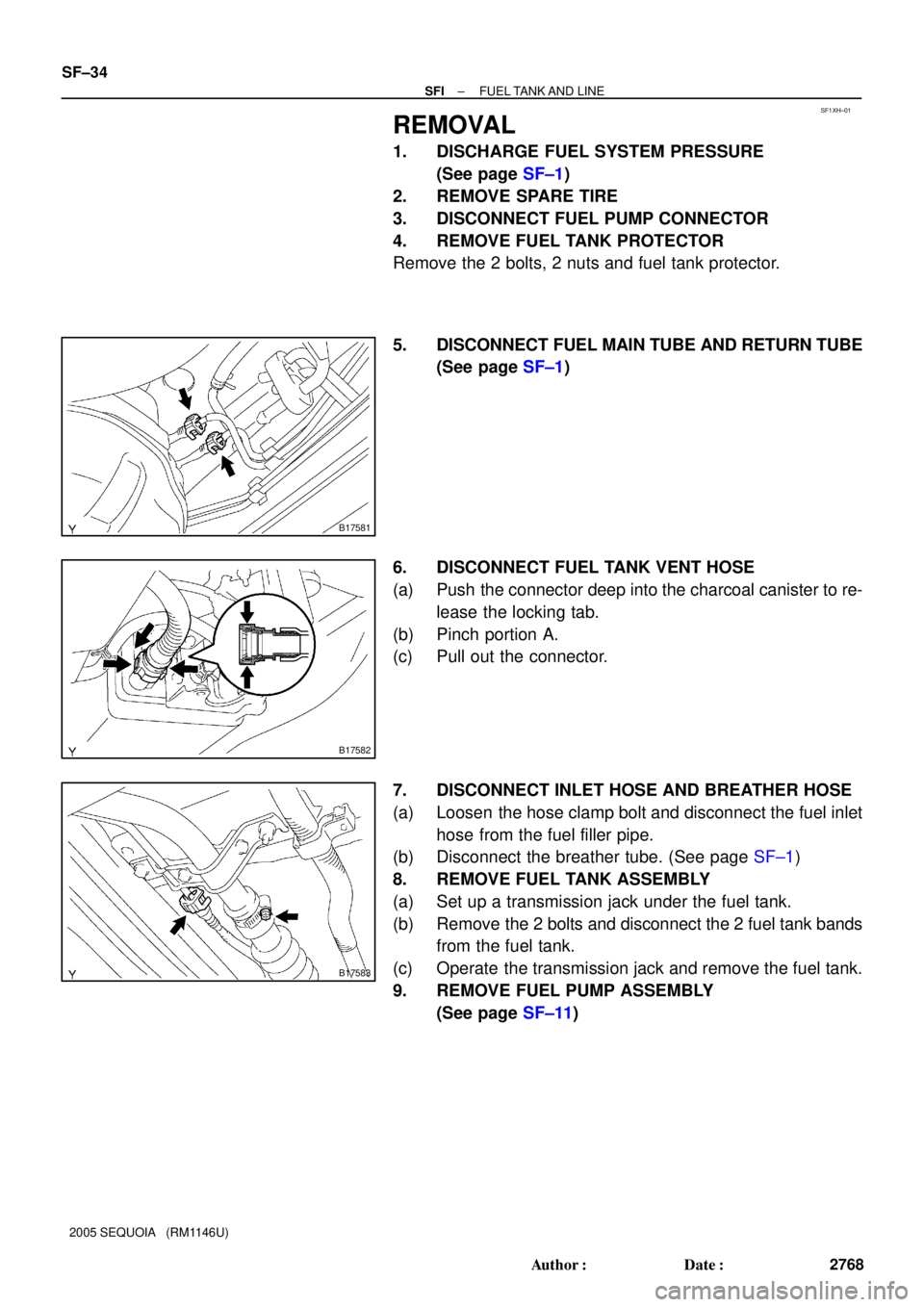
5. DISCONNECT FUEL MAIN TUBE AND RETURN TUBE
(See page SF±1)
6. DISCONNECT FUEL TANK VENT HOSE
(a) Push the connector deep into the charcoal canister to re-
lease the locking tab.
(b) Pinch portion A.
(c) Pull out the connector.
7. DISCONNECT INLET HOSE AND BREATHER HOSE
(a) Loosen the hose clamp bolt and disconnect the fuel inlet
hose from the fuel filler pipe.
(b) Disconnect the breather tube. (See page SF±1)
8. REMOVE FUEL TANK ASSEMBLY
(a) Set up a transmission jack under the fuel tank.
(b) Remove the 2 bolts and disconnect the 2 fuel tank bands
from the fuel tank.
(c) Operate the transmission jack and remove the fuel tank.
9. REMOVE FUEL PUMP ASSEMBLY
(See page SF±11)