Page 1098 of 4323

DI93A±03
Inspector 's
Name:
Customer 's Name
Date Vehicle
Brought InRegistration DateRegistration No.
Frame No.
Odometer Reading/ /
/ /
Date Problem First Occurred
Frequency Problem Occurs/ /
ContinuousIntermittent ( times a day)
Remains ONDoes not Light Up
DTC Check1st Time
2nd TimeNormal System Code
Trouble Code (Code )
Symptomskm
miles
Check ItemNormal
ABS does not operate.
ABS does not operate efficiently.
Does not Light Up
ABS & BA & TRAC & VSC Check Sheet
VSC does not operate. (Wheels sideslip when turning sharply.)
ABS Warning Light
Abnormal
Remains ON
Does not Light Up
Remains ONDoes not Light Up
Remains ONDoes not Light Up
Remains ONDoes not Light Up
TRAC OFF Indicator
Light Abnormal*1
SLIP Indicator
Light Abnormal VSC TRAC Warning
Light Abnormal
BRAKE Warning
Light Abnormal
Malfunction
Indicator Light
TRAC does not operate. (Wheels spin when starting off rapidly.)
Remains ON
Does not Light UpVSC OFF Indicator
Light Abnormal*2
BA does not operate
Normal System Code
Trouble Code (Code )
DI±896
± DIAGNOSTICSABS WITH EBD & BA & TRAC & VSC SYSTEM
1090 Author�: Date�:
2005 SEQUOIA (RM1146U)
CUSTOMER PROBLEM ANALYSIS CHECK
*1: Only for 2WD
*2: Only for 4WD
Page 1102 of 4323

F02135
Start Position
End PositionWithin ± 5° DI±900
± DIAGNOSTICSABS WITH EBD & BA & TRAC & VSC SYSTEM
1094 Author�: Date�:
2005 SEQUOIA (RM1146U)
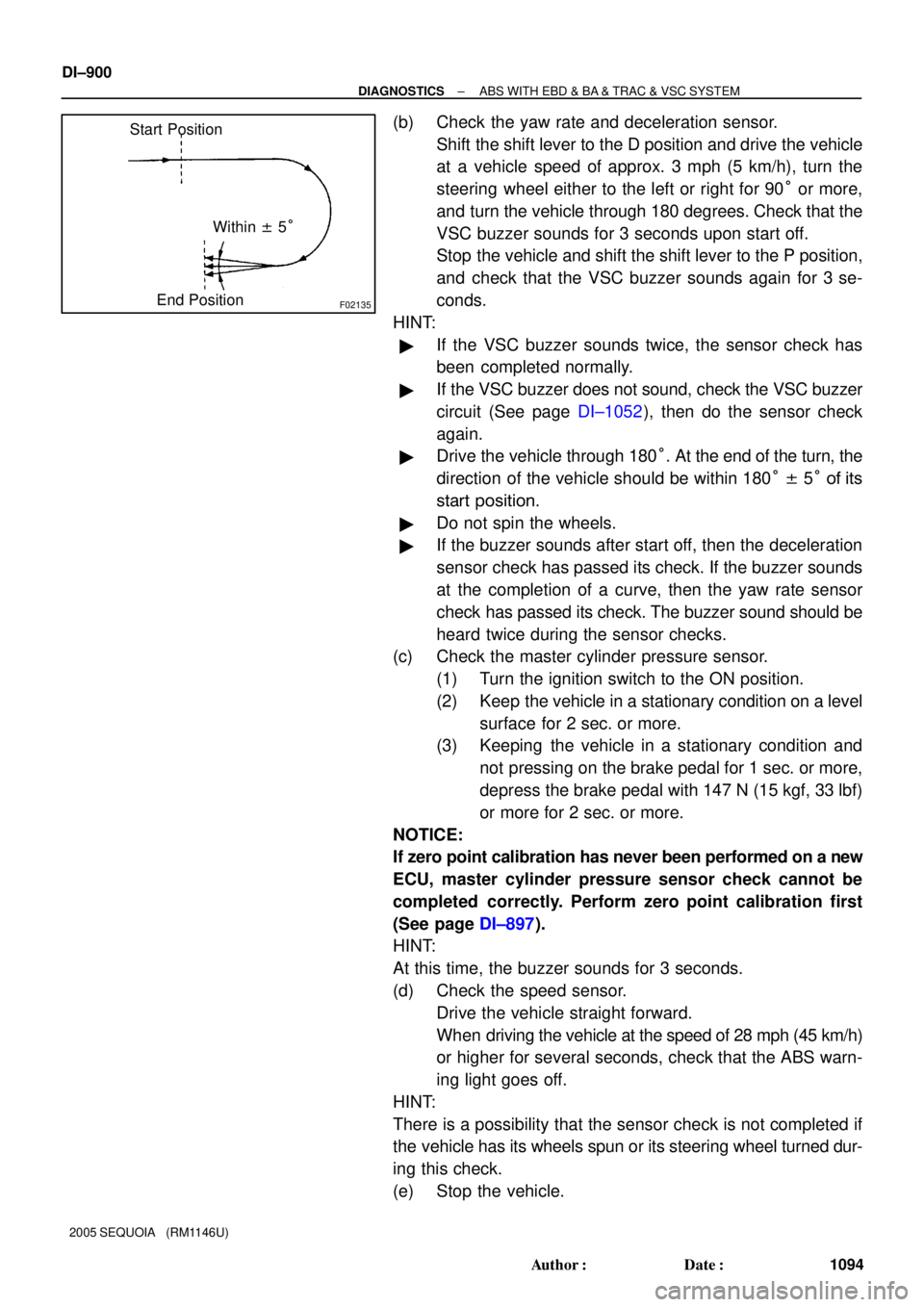
(b) Check the yaw rate and deceleration sensor.
Shift the shift lever to the D position and drive the vehicle
at a vehicle speed of approx. 3 mph (5 km/h), turn the
steering wheel either to the left or right for 90° or more,
and turn the vehicle through 180 degrees. Check that the
VSC buzzer sounds for 3 seconds upon start off.
Stop the vehicle and shift the shift lever to the P position,
and check that the VSC buzzer sounds again for 3 se-
conds.
HINT:
�If the VSC buzzer sounds twice, the sensor check has
been completed normally.
�If the VSC buzzer does not sound, check the VSC buzzer
circuit (See page DI±1052), then do the sensor check
again.
�Drive the vehicle through 180°. At the end of the turn, the
direction of the vehicle should be within 180° ± 5° of its
start position.
�Do not spin the wheels.
�If the buzzer sounds after start off, then the deceleration
sensor check has passed its check. If the buzzer sounds
at the completion of a curve, then the yaw rate sensor
check has passed its check. The buzzer sound should be
heard twice during the sensor checks.
(c) Check the master cylinder pressure sensor.
(1) Turn the ignition switch to the ON position.
(2) Keep the vehicle in a stationary condition on a level
surface for 2 sec. or more.
(3) Keeping the vehicle in a stationary condition and
not pressing on the brake pedal for 1 sec. or more,
depress the brake pedal with 147 N (15 kgf, 33 lbf)
or more for 2 sec. or more.
NOTICE:
If zero point calibration has never been performed on a new
ECU, master cylinder pressure sensor check cannot be
completed correctly. Perform zero point calibration first
(See page DI±897).
HINT:
At this time, the buzzer sounds for 3 seconds.
(d) Check the speed sensor.
Drive the vehicle straight forward.
When driving the vehicle at the speed of 28 mph (45 km/h)
or higher for several seconds, check that the ABS warn-
ing light goes off.
HINT:
There is a possibility that the sensor check is not completed if
the vehicle has its wheels spun or its steering wheel turned dur-
ing this check.
(e) Stop the vehicle.
Page 1105 of 4323

± DIAGNOSTICSABS WITH EBD & BA & TRAC & VSC SYSTEM
DI±903
1097 Author�: Date�:
2005 SEQUOIA (RM1146U)
HINT:
�If the VSC buzzer sounds twice, the sensor check has
been completed normally.
�If the VSC buzzer does not sound, check the VSC buzzer
circuit (see page DI±1052), then do the sensor check
again.
�Drive the vehicle through 180°. At the end of the turn its
check, the direction of the vehicle should be within 180°
± 5° of its start position.
�Do not spin the wheels.
�If the buzzer sounds after start off, then the deceleration
sensor check has passed its check. If the buzzer sounds
at the completion of a turn its check, then the yaw rate
sensor check has passed. The buzzer sound should be
heard during the sensor checks.
(c) Check the master cylinder pressure sensor.
(1) Turn the ignition switch to the ON position.
(2) Keep the vehicle in a stationary condition on a level
surface for 2 sec. or more.
(3) Keeping the vehicle in a stationary condition and
not pressing on the brake pedal for 1 sec. or more,
depress the brake pedal with 147 N (15 kgf, 33 lbf)
or more for 2 sec. or more on a new ECU.
NOTICE:
If zero point calibration has never been performed on a new
ECU, master cylinder pressure sensor check cannot be
completed correctly. Perform zero point calibration first
(See page DI±897).
HINT:
At this time, the buzzer sounds for 3 seconds.
(d) Check the speed sensor.
Drive the vehicle straight forward.
When driving the vehicle at the speed of 28 mph (45 km/h)
or higher for several seconds, check that the ABS warn-
ing light goes off.
HINT:
There is a case that the sensor check is not completed if the ve-
hicle has its wheels spun or its steering wheel turned during this
check.
(e) Stop the vehicle.
(f) Read the DTC by following the prompts on the tester
screen.
HINT:
Refer to the hand±held tester operator's manual for further de-
tails.
Page 1545 of 4323
H23999
Occupant
Classification ECU
O6 +B1
BL11
W±R
J49
O6IG 7
O6GND 3 W±R C J/C
I
J48 W±R 2
3D 1
3ASub J/B No. 3
W±R
W±R
W±R
W±B
W±B
BL16 BL12
B±O B±O
J45B J/C
I
J44 B±O 2
4C 2
4DSub J/B No. 4
B±O
Instrument Panel J/B
17
1E 2
1CIGN1
3
1C
2
1E3
1J7
1J I18
Ignition SW
IG2B±R
AM26
5
W±RW±R
Engine Room J/B
8
2C
1
2DECU±B Short Pin
1
2C AM2 F10
FL Block
54B
B
Battery
BK
± DIAGNOSTICSSUPPLEMENTAL RESTRAINT SYSTEM
DI±1343
1537 Author�: Date�:
2005 SEQUOIA (RM1146U)
WIRING DIAGRAM
Page 1717 of 4323
I28446
B±R
W±B W±RW±L
W±B W±RW±RW±R
W±R B±R
B±R B±R
W±R L±O L±O L±O
L±O
B±Y B±R
L±O
1 2
34 5
68
5
4A
B CF
I
W
B A
A A
BB
W±B 8 11
3L CG
1C
1E 1F
1G
1J
2C 2D3A 3C
1L
1C 3A 3A
4
164
12 219
15 16 88Sub J/B No. 3J/C
J/CJ24 J/C
J/C
111Sub J/B No. 3J31 J32
J37 J38 J33 J34
J33 J34
J24 J/C Instrument Panel J/B
I18
Ignition SW
Engine Room J/B F10
FL Block
ALT
8BI2 M7
M6
M6 BI2
BI2Position Control
ECU & Switch
+B
IG
SYSB
GND 1
2
BI2
Battery
BHAM1 AM1 PWR SEATECU±IG
IG1
M7 ECU±B Short Pin
± DIAGNOSTICSPOWER SEAT CONTROL SYSTEM (w/ Driving Position
Memory)DI±1515
1709 Author�: Date�:
2005 SEQUOIA (RM1146U)
WIRING DIAGRAM
Page 1756 of 4323
I21525
Pushed in Free Stop Light Switch:
DI±1554
± DIAGNOSTICSCRUISE CONTROL SYSTEM
1748 Author�: Date�:
2005 SEQUOIA (RM1146U)
2 Check operation of stop light.
CHECK:
Check that stop lights come on when the brake pedal is depressed, and go off when the brake pedal is re-
leased.
OK:
The stop lights operate normally.
OK Go to step 5.
NG
3 Inspect stop light switch assy.
PREPARATION:
Disconnect the stop light switch assy connector.
CHECK:
Measure the resistance according to the value(s) in the table
below.
OK:
Switch conditionTester connectionSpecified condition
Switch pin free1 ± 4Below 1 W
Switch pin free2 ± 310 kW or higher
Switch pin pushed in1 ± 410 kW or higher
Switch pin pushed in2 ± 3Below 1 W
NG Replace stop light switch assy.
OK
Page 1797 of 4323
I24831
Transponder Key ECU
Sub J/B No. 3
+B
J43
J/C
51
O
BatteryF10
FL BlockW±R
B
4
IG BEngine Room J/B W±R32
1J
1E Instrument Panel J/B
A
AGND O14
T16 T16 1
2
W±R
3A 3B
81
2C
2D ECU±B
SHORT PIN
± DIAGNOSTICSENGINE IMMOBILISER SYSTEM
DI±1595
1789 Author�: Date�:
2005 SEQUOIA (RM1146U)
Power source circuit
CIRCUIT DESCRIPTION
This circuit provides power to operate the transponder key ECU.
WIRING DIAGRAM
DI7TO±07
Page 1831 of 4323
I28557
I18
Ignition SWInstrument Panel J/BCombination Meter
Engine Room J/B
Sub J/B No. 4
IEBattery J8
J/CIA5 F10
Fusible
Link BlockC6
C5 C6
C6
C5 1F
1J
1C1D
1H
1C
1C1D
1D
1J
1J
2C 2D
222C
4B 4A AM2IG2
ST2
(*1) (*2)
W±B
W±R
B±R
B±WBR
B±O W±R
B±R
W±R W±RB±R
B±R B
AB
B
BB 893
98
2
1 1
1 4
5Short Pin
ECU±B
AM2
STA 4 5
8 211 9
37 6
53 396
IGN1
IGN212
23
24
28
Engine Room R/B
*1: Head (USA)
*2: Tail (CANADA)
± DIAGNOSTICSCOMBINATION METER SYSTEM
DI±1629
1823 Author�: Date�:
2005 SEQUOIA (RM1146U)
WIRING DIAGRAM