Page 2372 of 4323

I28687
Main AVC±LAN:
(*1, 2)� Multi±display Controller
Sub±assy (*1)
� Rear Seat Audio
Controller (*2) Radio and Navigation Assy Stereo Component
Amplifier Assy
Sub AVC±LAN:
Disc Player
Controller (*1) Television Display Assy (*1)
*1 w/ RSE
*2: w/ RSA
: AVC±LAN DI±2170
± DIAGNOSTICSNAVIGATION SYSTEM
2364 Author�: Date�:
2005 SEQUOIA (RM1146U)
6. AVC±LAN Description
(a) What is AVC±LAN?
AVC±LAN, an abbreviation for ºAudio Visual Communication Local Area Networkº, is a united standard
developed by the manufacturers in affiliation with Toyota Motor Corporation. This standard pertains
to audio and visual signals as well as switch and communication signals.
(b) Purpose:
Recently, car audio systems have rapidly developed and the functions vastly changed. The conven-
tional car audio system is being integrated with multi±media interfaces similar to those in navigation
systems. At the same time, customers are demanding higher quality from their audio systems. This
is merely an overview of the standardization background. The specific purposes are as follows.
(1) To solve sound problems, etc. caused by using components of different manufacturers through
signal standardization.
(2) To allow each manufacturer to concentrate on developing products they do best. From this, rea-
sonably priced products can be produced.
Page 2458 of 4323
I28474
11 Radio and
Navigation Assy
ACC
1
20
GND GR 1
RAD No. 24 3 A36
ACC Cut Relay
P
3
1 AM1 ACC12 Sub J/B No. 3
3A
W±R
W±R1
IA1 24
L±Y L±Y
2B
3
2C8
2D1 Engine Room J/B
RAD No. 1
ECU±BShort Pin 1J3
1EW±R
1L1
1C6AM12
ALT
B
Battery
IOBRR30 3A
I18
Ignition SWW±LB 212 1
1C 1FGR
GRB C B±O
J37To ECM
J38
Instrument Panel J/B
1 2B
R30
R30 J/C
PW W±R
B 8
54F10
FL Block DI±2256
± DIAGNOSTICSNAVIGATION SYSTEM
2450 Author�: Date�:
2005 SEQUOIA (RM1146U)
Power source circuit (Radio and navigation assy)
CIRCUIT DESCRIPTION
This circuit provides power to the radio and navigation assy.
WIRING DIAGRAM
DIDDB±01
Page 2460 of 4323
I28475
GR 1
4 3 A36
ACC Cut Relay
12 Sub J/B No. 3
3AW±R 1
2 3A
GRB C B±O
J37To ECM
J38
RAD No. 2
3
1 6AM1 212 1Instrument Panel J/B
1 2
P
3AM1
ACC W±R
W±L
ALT
B
Battery W±RIL12
L±W
2A
2C8
2D1 Engine Room J/B
RAD No. 3
ECU±BShort Pin 3
B B
BBJ11
J10 J11 L±W
IOBR
BRS10
S9
S9S9
S9 12
10
15
161ACC
B2+
B+
GND
E Stereo Component
Amplifier Assy
1J 1E
1L 1C 1C 1FJ/C
J/C
B
1GR
L±W
L±W
W±R
I18
Ignition SW P
W
8
4
5F10
FL Block DI±2258
± DIAGNOSTICSNAVIGATION SYSTEM
2452 Author�: Date�:
2005 SEQUOIA (RM1146U)
Power source circuit (Stereo component amplifier assy)
CIRCUIT DESCRIPTION
This circuit provides power to the stereo component amplifier assy.
WIRING DIAGRAM
DIDDD±01
Page 2568 of 4323
I24456
Integration Control
and Panel
Engine Room J/B
Battery
F10
Fusible Link
Block Instrument
Panel J/B
10 A DOMESHORT PIN R
1J3A 3E I19
2C2D
BSub J/B No. 3
BB
R581
3
54 16 6
1E
1 RR
+B DI±2366
± DIAGNOSTICSAIR CONDITIONING SYSTEM
2560 Author�: Date�:
2005 SEQUOIA (RM1146U)
Back±up Power Source Circuit
CIRCUIT DESCRIPTION
This is the back up power source for the integration control and panel. Power is supplied even when the
ignition switch is off and is used for diagnostic trouble code memory, etc.
WIRING DIAGRAM
DI3FL±10
Page 2611 of 4323

A04448
A23314
SST
A08660
A23315
SST
EM±24
± ENGINE MECHANICALTIMING BELT
2603 Author�: Date�:
2005 SEQUOIA (RM1146U)
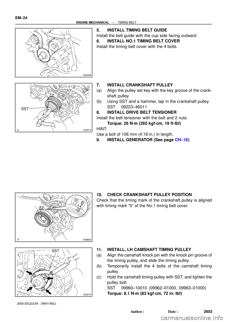
5. INSTALL TIMING BELT GUIDE
Install the belt guide with the cup side facing outward.
6. INSTALL NO.1 TIMING BELT COVER
Install the timing belt cover with the 4 bolts.
7. INSTALL CRANKSHAFT PULLEY
(a) Align the pulley set key with the key groove of the crank-
shaft pulley.
(b) Using SST and a hammer, tap in the crankshaft pulley.
SST 09223±46011
8. INSTALL DRIVE BELT TENSIONER
Install the belt tensioner with the bolt and 2 nuts.
Torque: 26 N´m (265 kgf´cm, 19 ft´lbf)
HINT:
Use a bolt of 106 mm (4.18 in.) in length.
9. INSTALL GENERATOR (See page CH±16)
10. CHECK CRANKSHAFT PULLEY POSITION
Check that the timing mark of the crankshaft pulley is aligned
with timing mark º0º of the No.1 timing belt cover.
11. INSTALL, LH CAMSHAFT TIMING PULLEY
(a) Align the camshaft knock pin with the knock pin groove of
the timing pulley, and slide the timing pulley.
(b) Temporarily install the 4 bolts of the camshaft timing
pulley.
(c) Hold the camshaft timing pulley with SST, and tighten the
pulley bolt.
SST 09960±10010 (09962±01000, 09963±01000)
Torque: 8.1 N´m (83 kgf´cm, 72 in.´lbf)
Page 2612 of 4323

A23316
Hold
SST
A23317
Turn
SST
A23318
SST
Tension
Turn
A23319
SST
Turn
± ENGINE MECHANICALTIMING BELT
EM±25
2604 Author�: Date�:
2005 SEQUOIA (RM1146U)
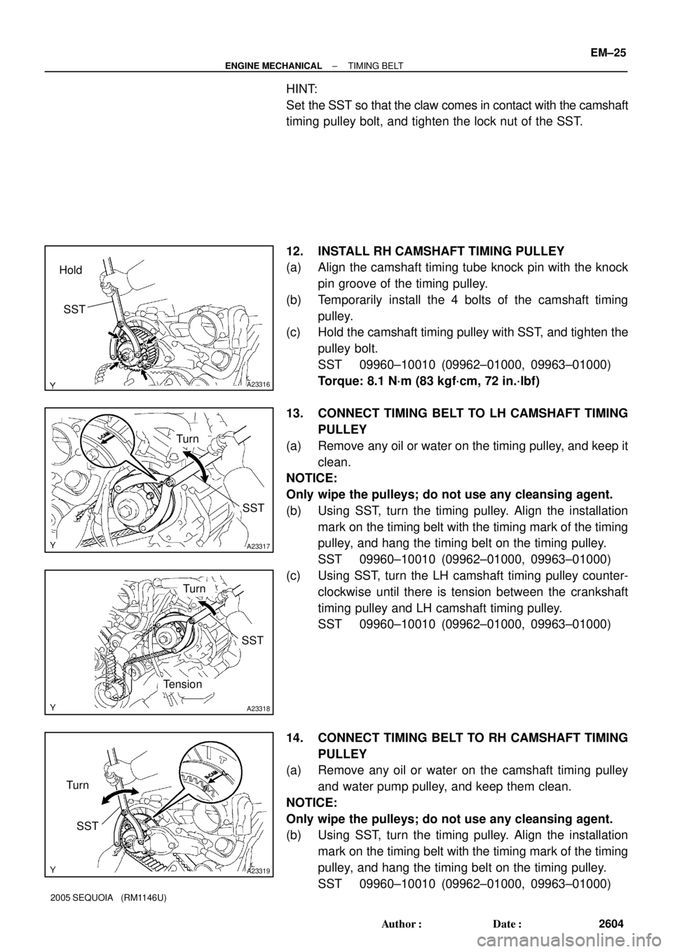
HINT:
Set the SST so that the claw comes in contact with the camshaft
timing pulley bolt, and tighten the lock nut of the SST.
12. INSTALL RH CAMSHAFT TIMING PULLEY
(a) Align the camshaft timing tube knock pin with the knock
pin groove of the timing pulley.
(b) Temporarily install the 4 bolts of the camshaft timing
pulley.
(c) Hold the camshaft timing pulley with SST, and tighten the
pulley bolt.
SST 09960±10010 (09962±01000, 09963±01000)
Torque: 8.1 N´m (83 kgf´cm, 72 in.´lbf)
13. CONNECT TIMING BELT TO LH CAMSHAFT TIMING
PULLEY
(a) Remove any oil or water on the timing pulley, and keep it
clean.
NOTICE:
Only wipe the pulleys; do not use any cleansing agent.
(b) Using SST, turn the timing pulley. Align the installation
mark on the timing belt with the timing mark of the timing
pulley, and hang the timing belt on the timing pulley.
SST 09960±10010 (09962±01000, 09963±01000)
(c) Using SST, turn the LH camshaft timing pulley counter-
clockwise until there is tension between the crankshaft
timing pulley and LH camshaft timing pulley.
SST 09960±10010 (09962±01000, 09963±01000)
14. CONNECT TIMING BELT TO RH CAMSHAFT TIMING
PULLEY
(a) Remove any oil or water on the camshaft timing pulley
and water pump pulley, and keep them clean.
NOTICE:
Only wipe the pulleys; do not use any cleansing agent.
(b) Using SST, turn the timing pulley. Align the installation
mark on the timing belt with the timing mark of the timing
pulley, and hang the timing belt on the timing pulley.
SST 09960±10010 (09962±01000, 09963±01000)
Page 2637 of 4323

Z03988
45°30°
1.0 ± 1.4 mm
Z03989
60°45°
1.0 ± 1.4 mm
EM6331
EM0988
Deviation EM±50
± ENGINE MECHANICALCYLINDER HEAD
2629 Author�: Date�:
2005 SEQUOIA (RM1146U)
(c) Check the valve face and seat for the following:
�If blue appears 360° around the face, the valve is
concentric. If not, replace the valve.
�If blue appears 360° around the valve seat, the
guide and face are concentric. If not, resurface the
seat.
�Check that the seat contact is in the middle of the
valve face with the following width:
1.0 to 1.4 mm (0.039 to 0.055 in.)
If not, correct the valve seats as follows:
�If the seating is too high on the valve face, use 30°
and 45° cutters to correct the seat.
�If the seating is too low on the valve face, use 60°
and 45° cutters to correct the seat.
(d) Hand±lap the valve and valve seat with an abrasive com-
pound.
(e) After hand±lapping, clean the valve and valve seat.
13. INSPECT VALVE SPRINGS
(a) Using a steel square, measure the deviation of the valve
spring.
Maximum deviation: 2.0 mm (0.079 in.)
If the deviation is greater than maximum, replace the valve
spring.
Page 2645 of 4323

EM0L4±09
P08885
Adhesive
15 mm (0.59 in.)
A03212
Protrusion
A05710
SST
A05711
(1)(2)(3)(4)
EM±58
± ENGINE MECHANICALCYLINDER HEAD
2637 Author�: Date�:
2005 SEQUOIA (RM1146U)
REASSEMBLY
HINT:
�Thoroughly clean all parts to be assembled.
�Before installing the parts, apply fresh engine oil to all slid-
ing and rotating surfaces.
�Replace all gaskets and oil seals with new ones.
1. INSTALL SPARK PLUG TUBES
HINT:
When using a new cylinder head, spark plug tubes must be
installed.
(a) Apply adhesive to the end of the spark plug tube.
Adhesive:
Part No. 08833±00070, THREE BOND 1324
or equivalent
(b) Using a wooden block and hammer, tap in a new spark
tube until there is 40.9 ± 42.1 mm (1.610 ± 1.658 in.) pro-
truding from the camshaft bearing cap installation surface
of the cylinder head.
NOTICE:
Avoid tapping a new spark plug tube too far for measuring
the amount of the protrusion while tapping.
2. INSTALL VALVES
(a) Using SST, push in a new oil seal.
SST 09201±41020
(b) Install the valve (1), spring seat (2), valve spring (3) and
spring retainer (4).