Page 2776 of 4323
SF1XH±01
B17581
B17582
B17583
SF±34
± SFIFUEL TANK AND LINE
2768 Author�: Date�:
2005 SEQUOIA (RM1146U)
REMOVAL
1. DISCHARGE FUEL SYSTEM PRESSURE
(See page SF±1)
2. REMOVE SPARE TIRE
3. DISCONNECT FUEL PUMP CONNECTOR
4. REMOVE FUEL TANK PROTECTOR
Remove the 2 bolts, 2 nuts and fuel tank protector.
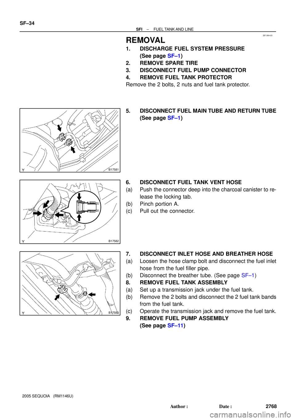
5. DISCONNECT FUEL MAIN TUBE AND RETURN TUBE
(See page SF±1)
6. DISCONNECT FUEL TANK VENT HOSE
(a) Push the connector deep into the charcoal canister to re-
lease the locking tab.
(b) Pinch portion A.
(c) Pull out the connector.
7. DISCONNECT INLET HOSE AND BREATHER HOSE
(a) Loosen the hose clamp bolt and disconnect the fuel inlet
hose from the fuel filler pipe.
(b) Disconnect the breather tube. (See page SF±1)
8. REMOVE FUEL TANK ASSEMBLY
(a) Set up a transmission jack under the fuel tank.
(b) Remove the 2 bolts and disconnect the 2 fuel tank bands
from the fuel tank.
(c) Operate the transmission jack and remove the fuel tank.
9. REMOVE FUEL PUMP ASSEMBLY
(See page SF±11)
Page 2826 of 4323

REPLACEMENT
CAUTION:
To avoid the danger of being burned, do not remove the ra-
di")
CO0IP±12
B05864Drain PlugDrain Plug Drain Plug
CO±2
± COOLINGCOOLANT
2818 Author�: Date�:
2005 SEQUOIA (RM1146U)
REPLACEMENT
CAUTION:
To avoid the danger of being burned, do not remove the ra-
diator cap while the engine and radiator are still hot, as fluid
and steam can be blown out under pressure.
1. REMOVE ENGINE UNDER COVER
2. DRAIN ENGINE COOLANT
(a) Remove the radiator cap.
(b) Remove the 3 drain plugs on the engine and radiator, and
drain the coolant.
(c) Close the 3 drain plugs.
Torque: 12.7 N´m (130 kgf´cm, 9 ft´lbf) for engine
3. REFILL WITH ENGINE COOLANT
(a) Slowly fill the system with coolant.
Capacity: 11.6 liters (12.3 US qts, 10.2 Imp. qts)
NOTICE:
Do not use plain water alone.
HINT:
�Use of improper coolants may damage the engine cooling
system.
�Use ºToyota Super Long Life Coolantº or similar high qual-
ity ethylene glycol based non±silicate, non±amine, non±
nitrite, and non±borate coolant with long±life hybrid or-
ganic acid technology.
�New Toyota vehicles are filled with Toyota Super Long
Life Coolant (color is pink, premixed ethylene glycol con-
centration is approximately 50 % and freezing tempera-
ture is ±35°C (±31°F)). When replacing the coolant, Toyo-
ta Super long Life Coolant is recommended.
�Observe the coolant level inside the radiator by pressing
the inlet and outlet radiator hoses several times by hand.
if the coolant level goes down, add the coolant.
(b) Install the radiator cap.
(c) Bleed the cooling system.
(1) Start the engine, and open the heater water valve.
(2) Maintain the engine speed at 2,000 ± 2,500 rpm,
and warm up the engine.
(d) Stop the engine, and wait until the engine coolant cools
down.
(e) Refill coolant into the reservoir until it is ºFULLº.
4. CHECK FOR ENGINE COOLANT LEAKS
5. CHECK ENGINE COOLANT SPECIFIC GRAVITY COR-
RECTLY
6. REINSTALL ENGINE UNDER COVER
Page 2892 of 4323

P21088
Ohmmeter
No Continuity
P10821
Free
Lock
B12319
Terminal CTerminal 50
ContinuityOhmmeter
B12320ContinuityOhmmeter
Terminal 50
ST±10
± STARTINGSTARTER
2884 Author�: Date�:
2005 SEQUOIA (RM1146U)
12. INSPECT BRUSH HOLDER INSULATION
Using an ohmmeter, check that there is no continuity between
the positive (+) and negative (±) brush holders.
If there is continuity, repair or replace the brush holder.
13. INSPECT GEAR TEETH
Check the gear teeth on the pinion gear, idle gear and the clutch
assembly for wear or damage.
If any damage is found, replace the gear or clutch assembly,
and also check the drive plate ring gear for wear or damage.
14. INSPECT CLUTCH PINION GEAR
Rotate the pinion gear clockwise, and check that it turns freely.
Check that it locks by rotating the pinion gear counterclockwise.
If necessary, replace the clutch assembly.
15. INSPECT FRONT AND REAR BEARING
Turn the bearing by hand as applying inward force.
If resistance is felt or the bearing sticks, replace the bearing.
16. DO PULL±IN COIL OPEN CIRCUIT TEST
Using an ohmmeter, check that there is continuity between ter-
minals 50 and C.
If there is no continuity, replace the magnetic switch.
17. DO HOLDING COIL OPEN CIRCUIT TEST
Using an ohmmeter, check that there is continuity between ter-
minal 50 and the switch body.
If there is no continuity, replace the magnetic switch.
Page 2897 of 4323

ST094±06
B02289
Terminal 50
Battery Terminal C
B02290
Battery Terminal CDisconnect
B02291
Disconnect
Battery
B02292
Terminal 30
Battery Ammeter Terminal 50
± STARTINGSTARTER
ST±15
2889 Author�: Date�:
2005 SEQUOIA (RM1146U)
TEST
NOTICE:
These tests must be done within 3 to 5 seconds to avoid the
coil to be burned ± out.
1. DO PULL±IN TEST
(a) Disconnect the field coil lead wire from terminal C.
(b) Connect the battery to the magnetic switch as shown.
Check that the pinion gear moves outward.
2. DO HOLDING TEST
While connected as above with the pinion gear out, disconnect
the negative (±) lead from terminal C. Check that the pinion gear
remains out.
3. INSPECT CLUTCH PINION GEAR RETURN
Disconnect the negative (±) lead from the starter body. Check
that the pinion gear returns inward.
4. DO NO±LOAD PERFORMANCE TEST
(a) Connect the battery and ammeter to the starter as shown.
(b) Check that the starter rotates smoothly and steadily with
the pinion gear moving out. Check that the ammeter
shows the specified current.
Specified current:
At 11.5 V: 100 A or less
Page 2901 of 4323

CHARGING SYSTEM
ON±VEHICLE INSPECTION
C")
CH0K7±03
B07241
Upper Level
Lower Level
B07242
Except Maintenance±Free Battery
± CHARGINGCHARGING SYSTEM
CH±1
2893 Author�: Date�:
2005 SEQUOIA (RM1146U)
CHARGING SYSTEM
ON±VEHICLE INSPECTION
CAUTION:
�Check that the battery cables are connected to the
correct terminals.
�Disconnect the battery cables when the battery is giv-
en a quick charge.
�Do not perform tests with a high voltage insulation re-
sistance tester.
�Never disconnect the battery while the engine is run-
ning.
1. CHECK BATTERY ELECTROLYTE LEVEL
Check the electrolyte quantity of each cell.
If under the lower level, replace the battery (or add distilled wa-
ter if possible) and check the charging system.
2. Except Maintenance±Free Battery:
CHECK BATTERY SPECIFIC GRAVITY
Check the specific gravity of each cell.
Standard specific gravity:
1.25 to 1.29 at 20°C (68°F)
If the specific gravity is less than the specification, charge the
battery.
3. Maintenance±Free Battery:
CHECK BATTERY VOLTAGE
(a) In the case that 20 minutes have not passe4d after stop-
ping the engine, turn on the ignition switch and the electri-
cal system (headlight, blower motor, rear defogger, etc.)
for 60 seconds before removing the surface charge.
(b) Turn the ignition switch OFF and turn off the electrical sys-
tems.
Page 2914 of 4323
B16371
SST (C)
SST (A)
Insert
B16373
SST (C)
SST (A)
Turn
B16370SST (B)
SST (A) Turn
B16361
Upward
Pin
B16359
CH±14
± CHARGINGGENERATOR
2906 Author�: Date�:
2005 SEQUOIA (RM1146U)
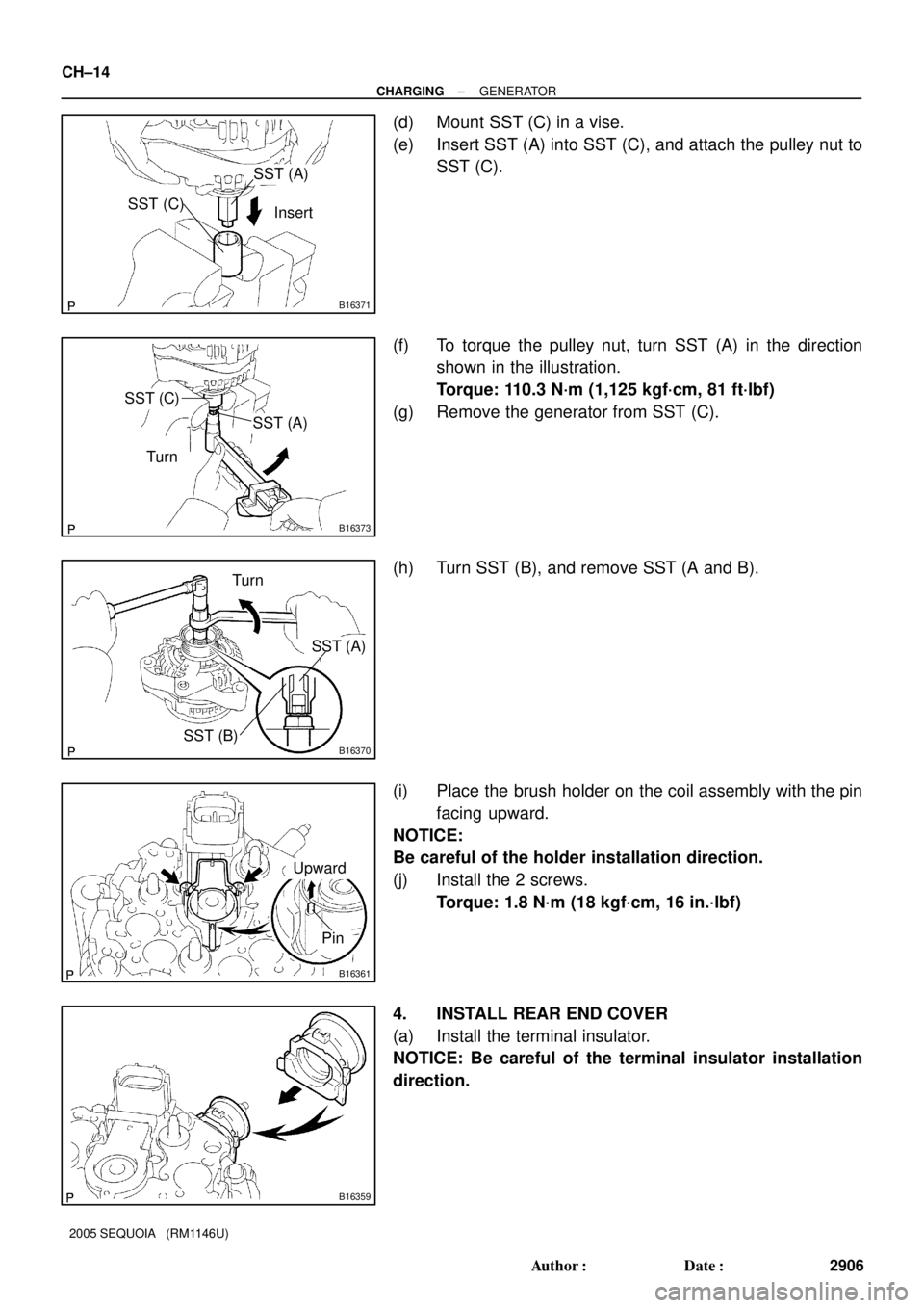
(d) Mount SST (C) in a vise.
(e) Insert SST (A) into SST (C), and attach the pulley nut to
SST (C).
(f) To torque the pulley nut, turn SST (A) in the direction
shown in the illustration.
Torque: 110.3 N´m (1,125 kgf´cm, 81 ft´lbf)
(g) Remove the generator from SST (C).
(h) Turn SST (B), and remove SST (A and B).
(i) Place the brush holder on the coil assembly with the pin
facing upward.
NOTICE:
Be careful of the holder installation direction.
(j) Install the 2 screws.
Torque: 1.8 N´m (18 kgf´cm, 16 in.´lbf)
4. INSTALL REAR END COVER
(a) Install the terminal insulator.
NOTICE: Be careful of the terminal insulator installation
direction.
Page 2927 of 4323

D12705
D14229
Shift
Solenoid
Valve SL2Shift
Solenoid
Valve SLUShift
Solenoid
Valve SR
Shift
Solenoid
Valve S2 Shift
Solenoid
Valve S1 Shift
Solenoid
Valve SL1 Shift
Solenoid
Valve SLT
D12707
Pin
± AUTOMATIC TRANSMISSION (A750E, A750F)VALVE BODY ASSEMBLY
AT±11
2919 Author�: Date�:
2005 SEQUOIA (RM1146U)
6. REMOVE VALVE BODY
(a) Remove the 19 bolts and the valve body.
(b) Remove the 3 drum seal gaskets.
7. REMOVE SOLENOID VALVE
(a) Remove the 2 bolts and the shift solenoid valve SR.
(b) Remove the 3 bolts and the shift solenoid valves S1 and
S2.
(c) Remove the 2 bolts, 2 solenoid lock plates and the 4
straight pins.
(d) Remove the shift solenoid valves SL2 and SLU.
(e) Remove the shift solenoid valves SL1 and SLT.
(f) Remove the O±ring from the solenoid valve S2.
8. INSTALL SOLENOID VALVE
(a) Install a new O±ring to the shift solenoid valve S2.
(b) Install the shift solenoid valves SL1 and SLT.
(c) Install the shift solenoid valves SL2 and SLU.
(d) Install the 4 straight pins and the 2 solenoid lock plates
with the 2 bolts.
Torque: 6.4 N´m (65 kgf´cm, 57 in´lbf)
(e) Install the shift solenoid valve S1 with the bolt.
Torque: 6.4 N´m (65 kgf´cm, 57 in´lbf)
(f) Install the shift solenoid valve S2 with the bolt.
Torque: 10 N´m (102 kgf´cm, 7 ft´lbf)
(g) Install the shift solenoid valve SR with the 2 bolts.
Torque: 6.4 N´m (65 kgf´cm, 57 in´lbf)
9. INSTALL VALVE BODY
HINT:
Align the groove of the manual valve with the pin of the lever.
(a) Install 3 new drum seal gaskets to the transmission case.
Page 2937 of 4323
COLUMN SHIFT ASSEMBLY
AT±21
2929 Author�: Date�:
2005 SEQUOIA (RM1146U)
INSTALLATION
1. INSTALL SHIFT LEVER HOUSING
Using a torx® so")
AT13D±01
D10678
D10679
± AUTOMATIC TRANSMISSION (A750E, A750F)COLUMN SHIFT ASSEMBLY
AT±21
2929 Author�: Date�:
2005 SEQUOIA (RM1146U)
INSTALLATION
1. INSTALL SHIFT LEVER HOUSING
Using a torx® socket wrench, install the shift lever housing with
3 new screws.
Torque: 12 N´m (120 kgf´cm, 9 ft´lbf)
2. INSTALL SHIFT LEVER
(a) Using a torx® socket wrench, install the shift lever with a
new screw.
Torque: 18 N´m (180 kgf´cm, 13 ft´lbf)
(b) Connect the connector.
3. INSTALL PARKING LOCK CABLE NO. 1 AND NO. 2
(a) Apply MP grease on the lock pin and internal surface of
shift lever housing.
(b) Install the spring and parking lock cable No. 1 into the shift
lever housing.
NOTICE:
Be careful not to bend or twist the cable abnormally.
(c) Using a torx® socket wrench, install 2 new screws.
Torque: 2.9 N´m (29 kgf´cm, 25 in.´lbf)
(d) Wire the cable No. 1 and No. 2, as shown in the illustra-
tion.
(e) Temporarily install the cable housing to steering column
assembly with 2 new bolts.
NOTICE:
Be careful not to bend or twist the cable abnormally.
(f) After installation, confirm the following items.
(1) When the shift lever is in P position and the pedal
button is pushed in by 7 mm (0.28 in.), shift lever
should be locked by lock pin.
(2) When the pedal button is released, the shift lever
should be able to be shifted from P position to other
positions.
(3) When the shift lever is in the N or D position and the
pedal button is pushed in by 7 mm (0.28 in.), the
shift lever should be able to be shifted.