Page 2953 of 4323
TR0CI±02
F19231
Low Planetary Ring Gear
x5Transfer
Case Cover
Output Shaft Front
Needle Roller Bearing
Oil Pump Gear
Magnet
118 (1,203, 87)
Thrust Bearing Race No. 1
N´m (kgf´cm, ft´lbf)
: Specified torque
� Non±reusable part
� Precoated partSnap Ring Case Plug
Breather Oil
Deflector
Front Output Shaft
Companion Flange
� � Compression Spring
Front Bearing
Retainer
Low Planetary Gear Bearing Low Planetary Gear
Input Gear Stopper
Planetary Carrier Washer
Oil Separator
7.5 (76, 66 in.´lbf)
Oil PumpSnap Ring
Transfer Front
Case
� Oil SealSpacer
Snap RingInput Shaft
Ball
Head Pin
� O±Ring
� Oil Seal� Oil Seal
18.6 (190, 14)
18 (184, 13)
11.5 (117, 8)
7.5 (76, 66 in.´lbf)
7.5 (76, 66 in.´lbf)
± TRANSFERTRANSFER ASSEMBLY
TR±7
2945 Author�: Date�:
2005 SEQUOIA (RM1146U)
TRANSFER ASSEMBLY
COMPONENTS
Page 2954 of 4323
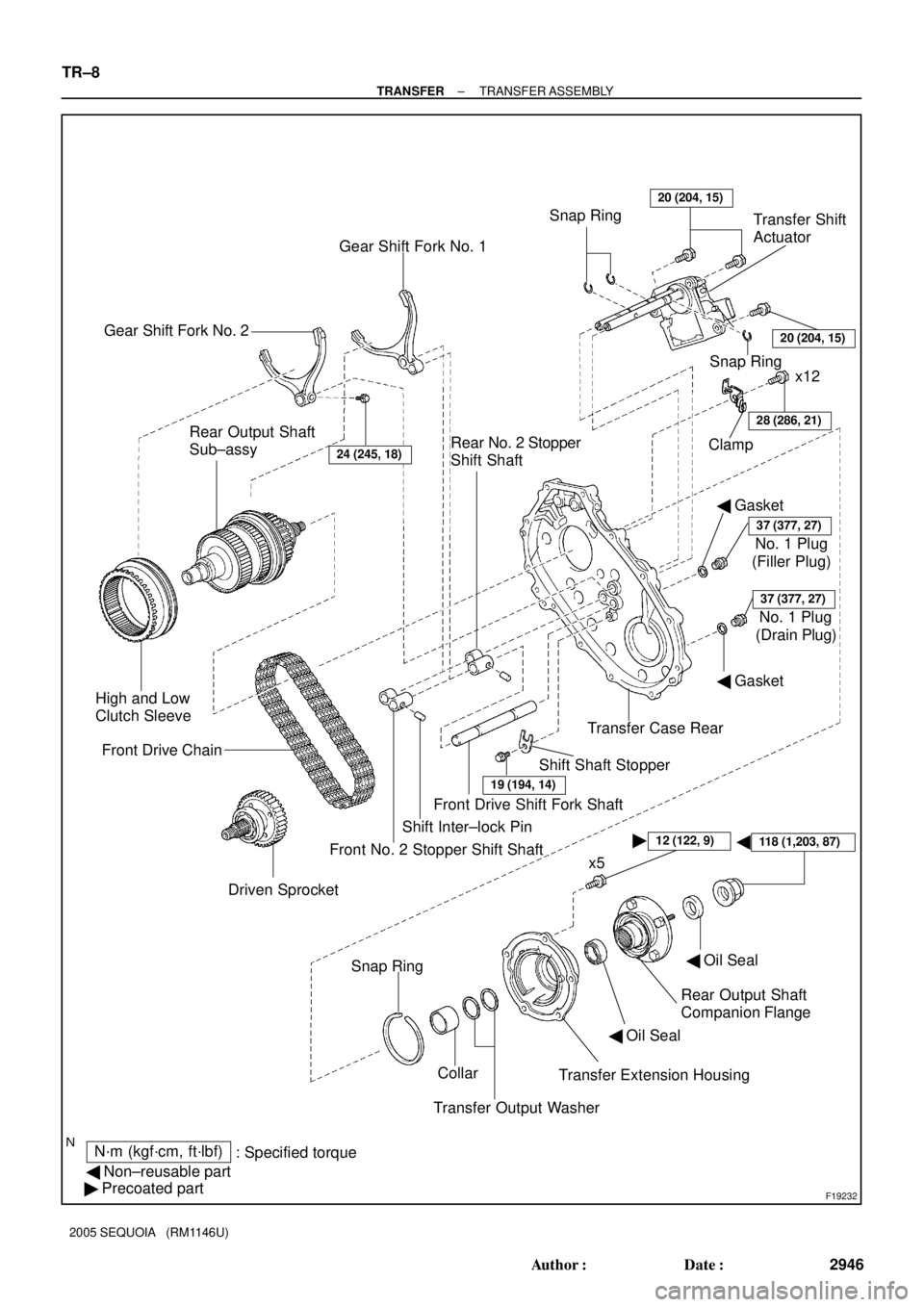
F19232
� �
N´m (kgf´cm, ft´lbf)
: Specified torque
� Non±reusable part
� Precoated partTransfer Extension Housing Collar Snap Ring
Transfer Output WasherRear Output Shaft
Companion Flange
24 (245, 18)
Driven Sprocket Front Drive Chain
19 (194, 14)
Shift Shaft Stopper Rear Output Shaft
Sub±assy
� Gasket
37 (377, 27)
(Filler Plug) Clamp
28 (286, 21)
x12
Gear Shift Fork No. 1
Rear No. 2 Stopper
Shift ShaftSnap RingTransfer Shift
Actuator
� Gasket
� Oil Seal High and Low
Clutch Sleeve
Gear Shift Fork No. 2
x5 Front No. 2 Stopper Shift ShaftShift Inter±lock PinFront Drive Shift Fork ShaftTransfer Case Rear Snap Ring20 (204, 15)
No. 1 Plug
37 (377, 27)
(Drain Plug) No. 1 Plug
� Oil Seal
12 (122, 9)
20 (204, 15)
118 (1,203, 87)
TR±8
± TRANSFERTRANSFER ASSEMBLY
2946 Author�: Date�:
2005 SEQUOIA (RM1146U)
Page 2956 of 4323

6. REMOVE TRANSFER EXTENSION HOUSING
(a) Remove the 5 bolts and transfer extension")
F19242
F19243
F19244
F19245
F19246
TR±10
± TRANSFERTRANSFER ASSEMBLY
2948 Author�: Date�:
2005 SEQUOIA (RM1146U)
6. REMOVE TRANSFER EXTENSION HOUSING
(a) Remove the 5 bolts and transfer extension housing.
HINT:
If necessary, tap on the transfer extension housing with a plas-
tic hammer to remove it.
(b) Using a screwdriver and hammer, remove the oil seal
from the transfer extension housing.
(c) Remove the 2 transfer output washers.
(d) Remove the collar.
7. REMOVE TRANSFER CASE REAR
(a) Remove the 12 bolts and clamp.
(b) Remove the transfer case rear.
HINT:
If necessary, tap on the transfer case rear with a plastic hammer
to remove it.
8. REMOVE GEAR SHIFT FORK NO. 2 AND HIGH AND
LOW CLUTCH SLEEVE
Remove the bolt, gear shift fork No.2 and high and low clutch
sleeve.
9. REMOVE SHIFT SHAFT STOPPER
Remove the bolt and shift shaft stopper.
10. REMOVE FRONT DRIVE SHIFT FORK SHAFT
(a) Turn the front drive shift fork shaft.
(b) Remove the front drive shift fork shaft from the rear case
aligning the cutout with the shift inter±lock pin.
Page 2957 of 4323
F19247
F19248
F19249
F19250
F19251
± TRANSFERTRANSFER ASSEMBLY
TR±11
2949 Author�: Date�:
2005 SEQUOIA (RM1146U)
(c) Using a magnetic finger, remove the 2 shift inter±lock
pins.
11. REMOVE FRONT NO. 2 STOPPER SHIFT SHAFT
12. REMOVE REAR OUTPUT SHAFT ASSEMBLY, GEAR
SHIFT FORK NO. 1, FRONT DRIVE CHAIN AND DRIV-
EN SPROCKET
(a) Using 2 screwdrivers and a hammer, tap out the snap
ring.
(b) Using 2 screwdrivers and a hammer, tap out the snap
ring.
(c) Using a snap ring expander, remove the snap ring.
(d) Mount the transfer case rear in a vise.
(e) Using a plastic hammer, carefully tap the transfer case
rear, and remove the rear output shaft assembly together
with the gear shift fork No. 1, front drive chain and driven
sprocket.
Page 2960 of 4323
F19265
F19266
F19267
Front
F19289
F19290
TR±14
± TRANSFERTRANSFER ASSEMBLY
2952 Author�: Date�:
2005 SEQUOIA (RM1146U)
19. REMOVE LOW PLANETARY GEAR
(a) Using a snap ring expander, remove the snap ring.
(b) Remove the input gear stopper, ball and planetary carrier
washer.
(c) Remove the input shaft from the low planetary gear.
(d) Remove the thrust bearing race No. 1 and low planetary
gear bearing.
20. REMOVE CASE PLUG
Remove the case plug, compression spring and head pin from
the transfer front case.
21. REMOVE LOW PLANETARY RING GEAR
(a) Using a screwdriver, remove the snap ring.
NOTICE:
Be careful not to damage the transfer front case.
Page 2962 of 4323
TR0DG±01
F19291
Front
F19292
F19289
F19267
Front
F19266
TR±16
± TRANSFERTRANSFER ASSEMBLY
2954 Author�: Date�:
2005 SEQUOIA (RM1146U)
REASSEMBLY
1. INSTALL LOW PLANETARY RING GEAR
(a) Install the low planetary ring gear to the front case.
(b) Using a screwdriver, install the snap ring.
2. INSTALL CASE PLUG
Install the head pin, compression spring and case plug to the
transfer front case.
Torque: 18.6 N´m (190 kgf´cm, 14 ft´lbf)
3. INSTALL LOW PLANETARY GEAR
(a) Install the thrust bearing race No. 1 and low planetary
gear bearing to the input shaft.
(b) Install the input shaft to the low planetary gear.
(c) Install the ball, planetary carrier washer and input gear
stopper.
Page 2966 of 4323
F19250
F19304
F19305
F19247
F19307
TR±20
± TRANSFERTRANSFER ASSEMBLY
2958 Author�: Date�:
2005 SEQUOIA (RM1146U)
(c) Using a snap ring expander, install the snap ring.
(d) Using a screwdriver and hammer, drive in the snap ring.
(e) Using a screwdriver and hammer, drive in the snap ring.
12. INSTALL FRONT NO. 2 STOPPER SHIFT SHAFT
13. INSTALL FRONT DRIVE SHIFT FORK SHAFT
(a) Install the 2 shift inter±lock pins.
(b) Turn the front drive shift fork shaft, and install it on the rear
case aligning the cutout with the inter±lock pin.
14. INSTALL SHIFT SHAFT STOPPER
Install the shift shaft stopper with the bolt.
Torque: 19 N´m (195 kgf´cm, 14 ft´lbf)
Page 2982 of 4323

INSPECTION
1. INSPECT PLANETARY PINION GEAR THRUST
CLEARANCE
Using a fe")
TR0DL±01
F19271
F19272
F19273
SST
F19295
SST
SST
TR±36
± TRANSFERPLANETARY GEAR
2974 Author�: Date�:
2005 SEQUOIA (RM1146U)
INSPECTION
1. INSPECT PLANETARY PINION GEAR THRUST
CLEARANCE
Using a feeler gauge, measure the thrust clearance of the plan-
etary pinion gear.
Standard clearance:
0.11 to 0.84 mm (0.0043 to 0.0331 in.)
Maximum clearance:
0.84 mm (0.0331 in.)
If the clearance exceeds the maximum, replace the planetary
gear.
2. INSPECT PLANETARY PINION GEAR RADIAL
CLEARANCE
Using a dial indicator, measure the radial clearance of the plan-
etary pinion gear.
Standard clearance:
0.009 to 0.038 mm (0.0004 to 0.0015 in.)
Maximum clearance:
0.038 mm (0.0015 in.)
If the clearance exceeds the maximum, replace the planetary
gear.
3. IF NECESSARY, REPLACE INPUT SHAFT BEARING
(a) Using a snap ring expander, remove the snap ring.
(b) Using SST and a press, remove the input shaft bearing.
SST 09554±30011, 09555±55010
(c) Using SST and a press, install a new bearing so that the
groove does not face the low planetary gear.
SST 09223±15020, 09515±30010, 09950±70010
(09951±07100)

Thrust Bearing Race No. 1
N´m (kgf´cm, ft´lbf)
: Specifi")